Problem Solutions – Chapter 3
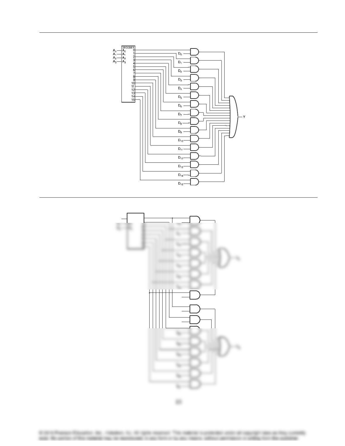
3-38.
3-39.
IA7
S0
DECODER
0
A0
IB1
IB0
Problem Solutions – Chapter 3
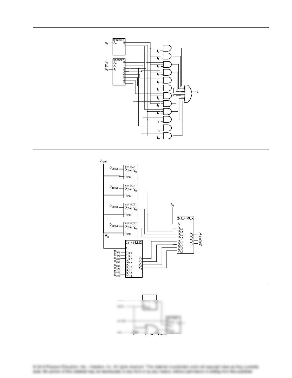
3-40.
3-41.
3-42.*
8x1 MUX
D(7:0)
3 OR gates
16
Problem Solutions – Chapter 3
17
3-43.*
A1
A0
E
D0
D1
D2
D3
0
0
0
0
0
0
0
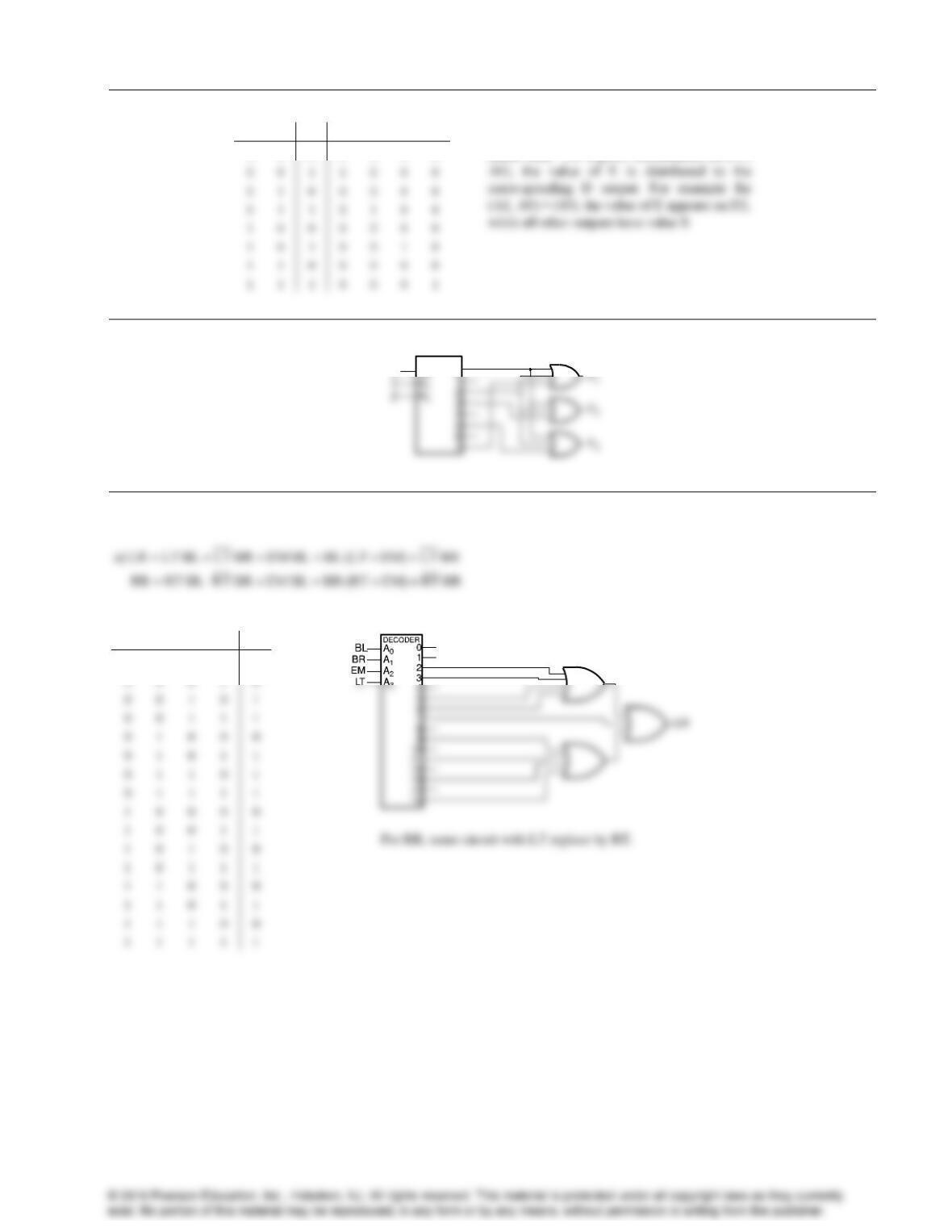
Consider E as the data input and A0, A1 as the
select lines. For a given combination on (A1,
3-44.
DECODER
0
A0
XF1
3-45.
b) Maximum of four inputs on OR gates assumed.
LT
EM
BR
BL
LR
0
0
0
0
0
0
0
0
1
0
0
0
1
0
1
0
0
1
1
1
0
1
0
0
0
0
1
0
1
1
0
1
1
0
1
0
1
1
1
1
1
0
0
0
0
1
0
0
1
1
1
0
1
0
0
1
0
1
1
1
1
1
0
0
0
1
1
0
1
1
1
1
1
0
0
1
1
1
1
1
0
0
1
1
0
0
0
0
1
0
0
0
0
0
1
0
0
0
0
0
0
1
0
1
0
0
1
0
1
1
0
0
0
0
0
1
1
1
0
0
0
1
Problem Solutions – Chapter 3
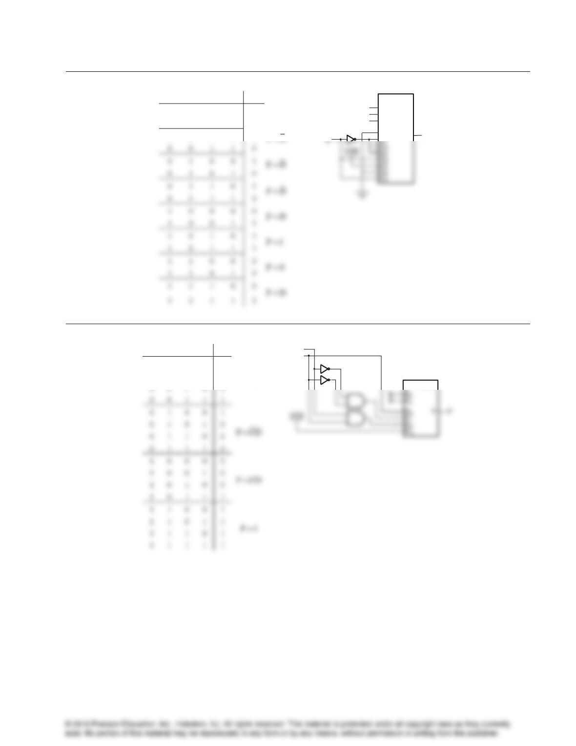
3-46.
A
B
C
D
F
F0
0
0
0
0
0
0
0
0
1
0
0
0
1
0
1
8 x 1 MUX
D0
Y
S0
S1
C
B
F
S2
A
3-47.*
A
B
C
D
F
0
0
0
0
0
FD
0
0
0
1
1
0
0
1
0
0
0
0
1
1
1
0
1
0
0
1
0
1
0
1
0
0
1
1
0
0
0
1
1
1
0
1
0
0
0
0
1
0
0
1
0
1
0
1
0
0
1
0
1
1
1
1
1
0
0
1
1
1
0
1
1
1
1
1
0
1
1
1
1
1
1
4 x 1 MUX
C
D
18
0
0
1
1
0
0
1
0
0
1
0
1
0
1
0
0
1
1
0
1
0
1
1
1
0
1
0
0
0
0
1
0
0
1
1
1
0
1
0
1
1
0
1
1
1
1
1
0
0
0
1
1
1
0
0
Problem Solutions – Chapter 3
19
3-48.
DECODER
0
1
2
A0
A1
A2
B
C
D
3-49.
0 0 0 0 0 0 0 0 0 0 0 0 0
S C A B C A B C A B C A B
1 0 0 0 0 0 0
C C A A B C B
3-50.*
1 3 2 1 0 2 0 0 0 0 0 0 0 0 0 0 0 0 0 0 0
( ) ( )( )C T T T C T A B C A B A B C A B A B C A B
T1
T3
T2
T4
3-51.*
Unsigned
1001 1100
1001 1101
1010 1000
0000 0000
1000 0000
1’s Complement
0110 0011
0110 0010
0101 0111
1111 1111
0111 1111
0110 0100
0110 0011
0101 1000
0000 0000
1000 0000
Problem Solutions – Chapter 3
20
3-52.
a)
11010
b)
11110
c)
1111110
d)
101001
+ 01111
+ 10010
+ 0000010
+ 111011
01001
10000
0000000
100100
3-54.*
+36 = 0100100
36
0100100
= 0001100
3-55.
a) b) c) d)
100111 -25 0010011 11 110001 -15 101110 -18
+ 111001 -7 + 100110 -26 + 101110 -18 + 001001 9
100000 -32 110001 -15 011111 -33 110111 -9
Overflow
3-56.+
a)
HD
b)
Bit
Cin
S
a)
11010
b)
11110
c)
1111110
d)
101001
+ 01111
+ 00010
+ 0000010
+ 000011
01001
00000
0000000
101100
Problem Solutions – Chapter 3
21
3-57.
3-58.
01B
0
in
C
0 0 0
10 S A A
3-59.
Proceeding from MSB to LSB:
if ( 1)
i i i i
A B A B A B
and for all
j i, ( 1)
j j j j j j
A B A B A B
Based on the above,
A
0
A
1
S
0
S
1
S
2
S
C
4
A
2
A
3
C
C
B
A
F
A
S
1
S
2
S
3
S
0
S
5
S
6
S
4
S
7
C
C
B
A
F
A
C
B
A
F
A
C
C
B
A
F
A
C
C
B
A
F
A
C
B
A
F
A
C
C
B
A
F
A
A
7
A
3
A
4
A
5
A
6
A
0
A
1
A
2
S
Problem Solutions – Chapter 3
3-60.+
A
B
Cin
Cout
A
B
Cin
Cout
3-61.
In a subtractor, the sum is replaced by the difference and the carry is replaced by the borrow. The borrow at
any given point is a 1 only if in the LSB direction from that point,
.AB
3-62.+
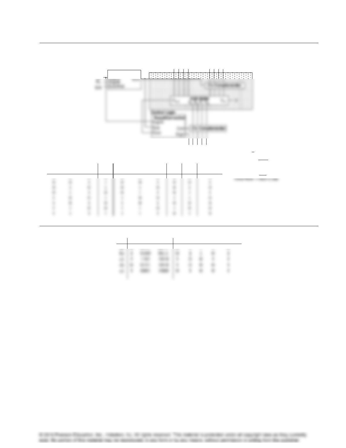
This problem requires two decisions: Is A > B? Is A = B? Two “carry” lines are required to build an iterative
circuit, Gi and Ei. These carries are assumed to pass through the circuit from right to left with G0 = 0 and E0 = 1.
Each cell has inputs Ai, Bi, Gi, and Ei and outputs Gi+1 and Ei+1. Using K-maps, cell equations are:
22
Problem Solutions – Chapter 3
23
3-63.+
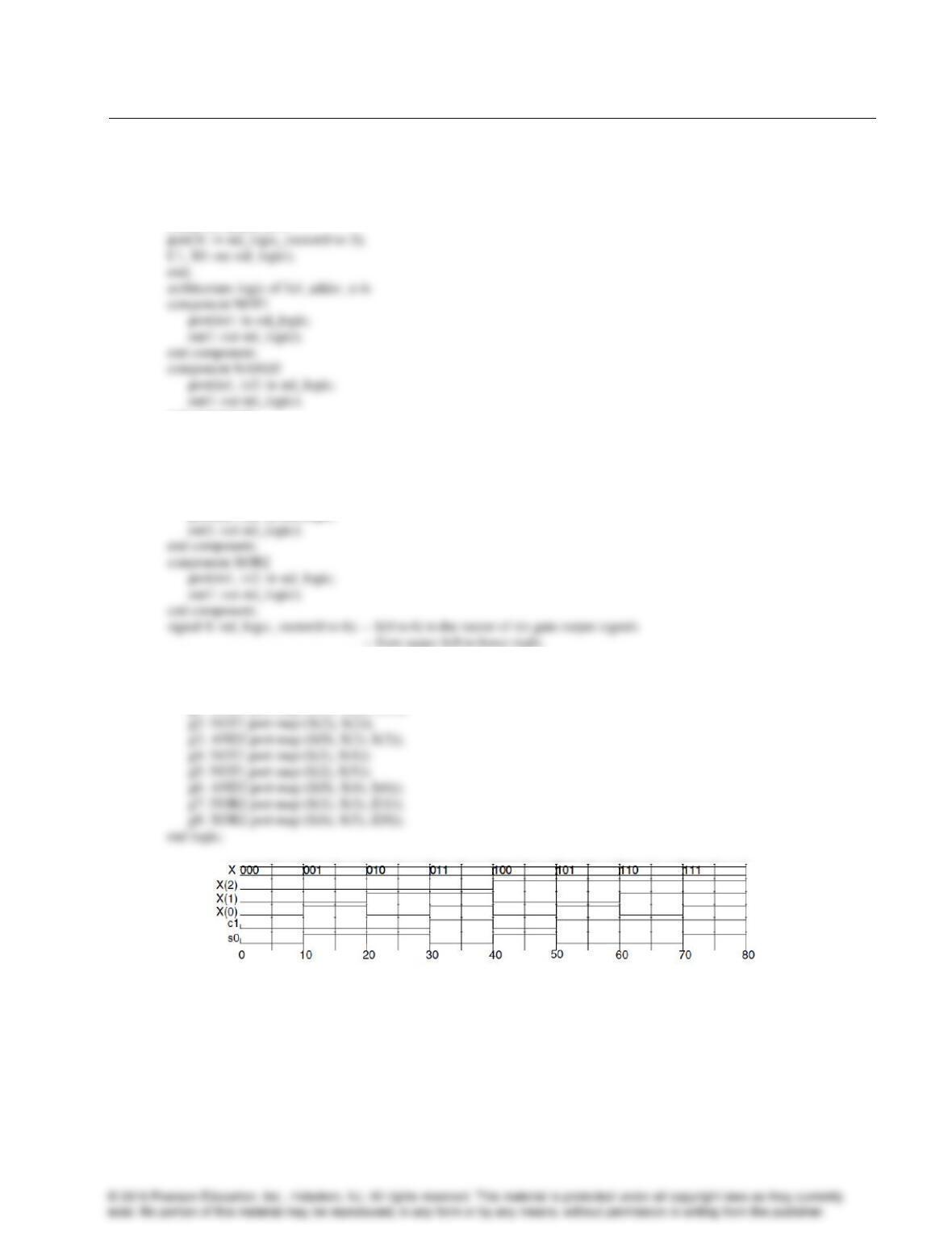
Circuit Diagram:
Add/Subtract
Control Logic
A3A2A1A0
A4
B3B2B1B0
Adder/Subtractor
S4S3S2S1S0
Control Logic Truth Tables
Inputs
Inputs
S/A
Sign A
SignB
Sub
Sub
SignA
Cout
Corr
Sign
Overflow
Sub S/A SignA SignB
Corr Sub Cout
Sign SignA Corr
3-64.*
S
A
B
C4
S3
S2
S1
S0
Problem Solutions – Chapter 3
3-65.
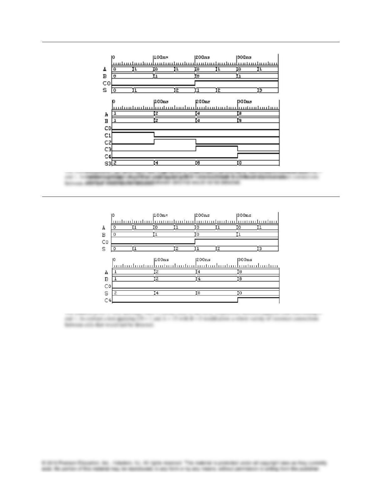
— Full Adder: Structural VHDL Description
— (See Figure 4-28 for logic diagram)
library ieee, lcdf_vhdl;
use ieee.std_logic_1164.all, lcdf_vhdl.func_prims.all; —X is input vector (A0, B0, C0).
entity full_adder_st is
end component;
component NOR2
port(in1, in2: in std_logic;
out1: out std_logic);
end component;
component AND2
port(in1, in2: in std_logic;
— from upper left to lower right.
—The following is the circuit netlist.
begin
g0: NAND2 port map (X(1), X(0), S(0));
g1: NOR2 port map (X(1), X(0), S(1));
24
Problem Solutions – Chapter 3
25
3-66.
3-67.*
Problem Solutions – Chapter 3
3-68.+
— prob_4-30 adder-subtractor with overflow detection
library ieee;
use ieee.std_logic_1164.all, ieee.std_logic_unsigned.all;
entity addsubov is
port(A,B: in std_logic_vector(3 downto 0);
S: in std_logic;
begin
with S select
Y(2 downto 0) <= B(2 downto 0) when ‘0’,
not B(2 downto 0) when ‘1’,
“XXX” when others;
with S select
Y(3) <= B(3) when ‘0’,
not B(3) when ‘1’,
‘X’ when others;
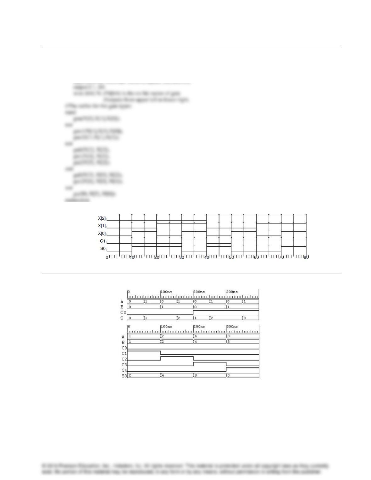
The solution given is very thorough since it checks each of the carry connections between adjacent cellstransferring 0 and 1.
26
Problem Solutions – Chapter 3
27
3-69.
// Full Adder: Structural Verilog Description
// (See Figure 4-28 for logic diagram)
module full_adder_st(C1, S0, X);
input [2:0] X; //X is the vector of inputs (A0, B0, C0).
3-70.
Problem Solutions – Chapter 3
28
3-71.*
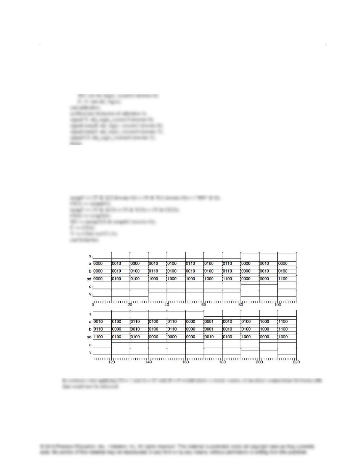
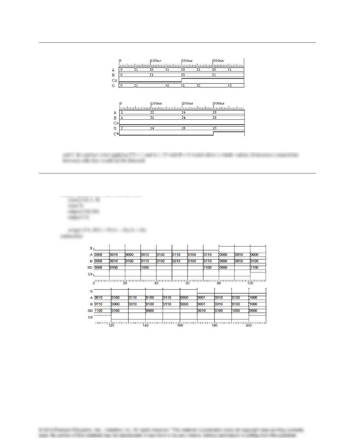
The solution given is very thorough since it checks each of the carry connections between adjacent cellstransferring 0
3-72.
// Adder-Subtractor Behavioral Model
module addsub_4b_v (S, A, B, SD, C4);