6140 CHAPTER 6. THE FREQUENCY-RESPONSE DESIGN METHOD
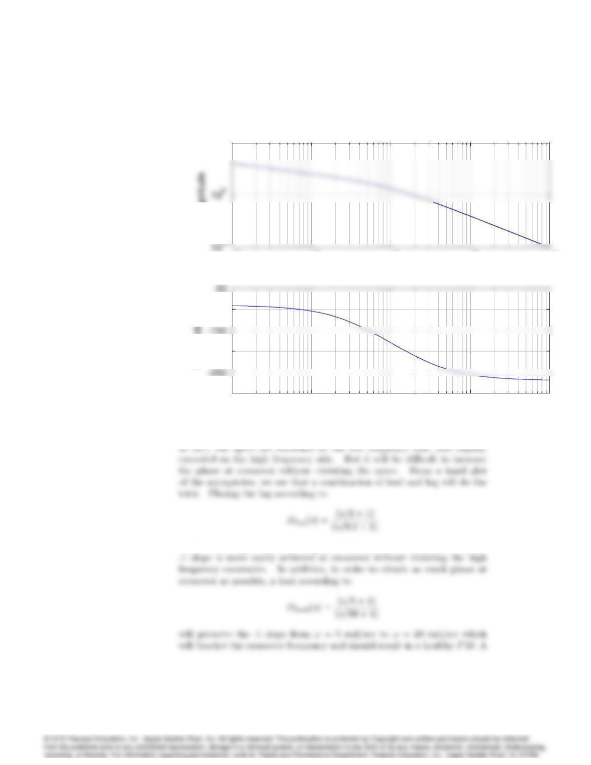
10-1 100101102103
105
ω (rad/sec)
Magnitude
Uncompensated Bode Plot
10-1 100101102103
105
ω (rad/sec)
Magnitude
Uncompensated Bode Plot
10-1 100101102103
-300
-200
-100
ω (rad/sec)
Phase (deg)
10-1 100101102103
105
ω (rad/sec)
Magnitude
Uncompensated Bode Plot
10-1 100101102103
105
ω (rad/sec)
Magnitude
Uncompensated Bode Plot
10-1 100101102103
-300
-200
-100
ω (rad/sec)
Phase (deg)
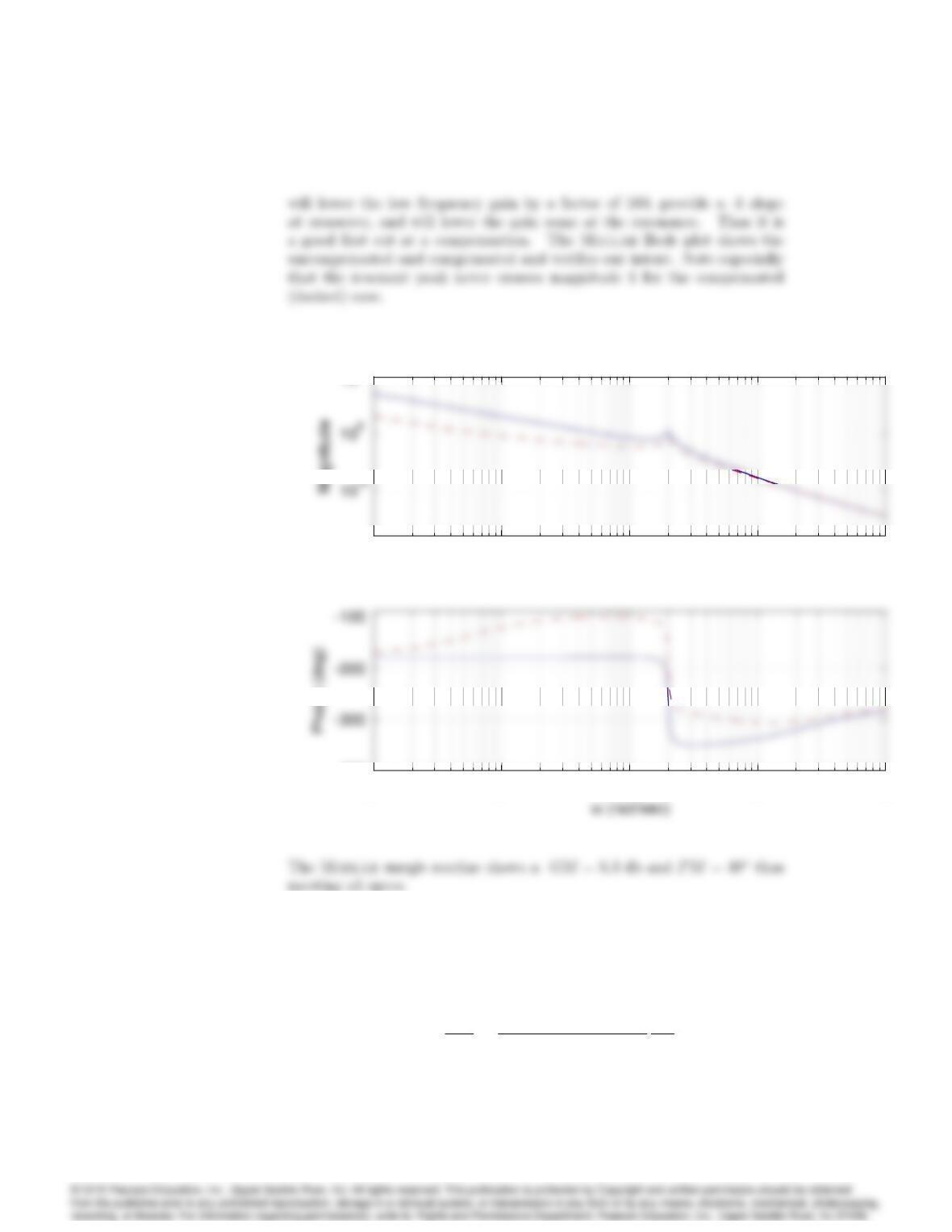
will lower the gain curve at frequencies just prior to crossover so that a
6141
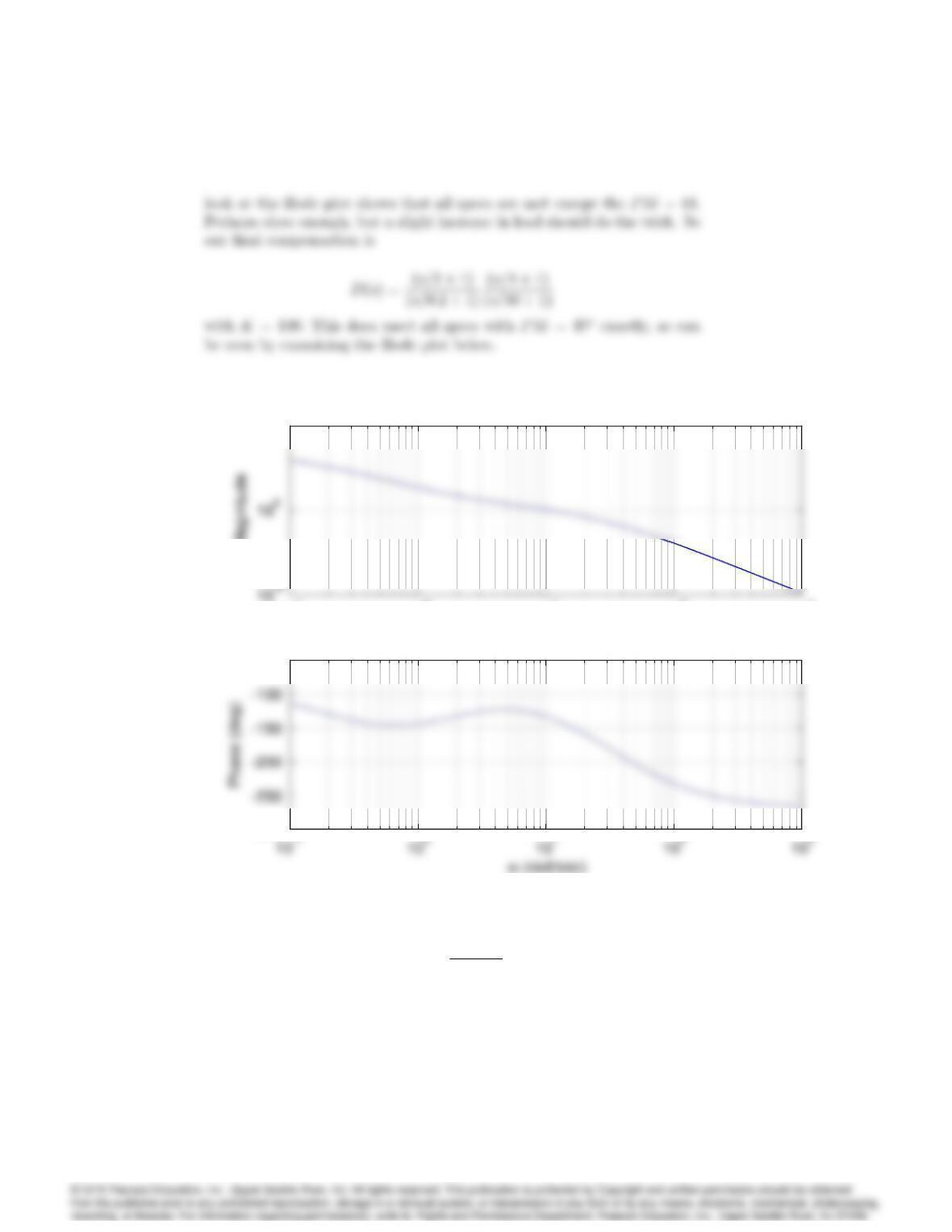
10-1 100101102103
105
ω (rad/sec)
Magnitude
Compensated Bode Plot
10-1 100101102103
105
ω (rad/sec)
Magnitude
Compensated Bode Plot
-300
-50
10-1 100101102103
105
ω (rad/sec)
Magnitude
Compensated Bode Plot
10-1 100101102103
105
ω (rad/sec)
Magnitude
Compensated Bode Plot
-300
-50
53. Consider a type I unity feedback system with
G(s) = K
s(s+ 1):
Design a lead compensator using Bode plot sketches so that Kv= 20 sec1
and PM >40. Use Matlab to verify and/or refine your design so that
it meets the specifications.
6142 CHAPTER 6. THE FREQUENCY-RESPONSE DESIGN METHOD
Solution :
Use a lead compensation :
From the specification, Kv= 20 sec1;
Adding a lead compensation
6143
–100
100
10
-2
10
-1
10
0
10
1
10
2
10
3
–180
–90
Bode Diagram
Gm = Inf dB (at Inf rad/sec) , Pm = 61.8 deg (at 6.99 rad/sec)
Frequency (rad/sec)
–100
100
10
-2
10
-1
10
0
10
1
10
2
10
3
–180
–90
54. Consider a satellite-attitude control system with the transfer function
G(s) = 0:05(s+ 25)
s2(s2+ 0:1s+ 4):
Amplitude-stabilize the system using lead compensation so that GM
2 (6 db), and PM 45, keeping the bandwidth as high as possible with
a single lead.
Solution :
The sketch of the uncompensated Bode plot asymptotes shows that the
6144 CHAPTER 6. THE FREQUENCY-RESPONSE DESIGN METHOD
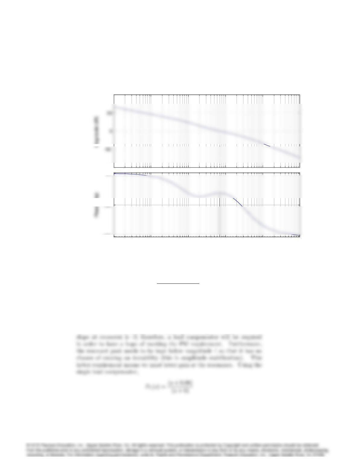
10-2 10-1 100101102
105
ω (rad/sec)
Bode Diagrams
10-2 10-1 100101102
-400
10-2 10-1 100101102
105
ω (rad/sec)
Bode Diagrams
10-2 10-1 100101102
105
ω (rad/sec)
Bode Diagrams
10-2 10-1 100101102
-400
10-2 10-1 100101102
105
ω (rad/sec)
Bode Diagrams
55. In one mode of operation the autopilot of a jet transport is used to con-
trol altitude. For the purpose of designing the altitude portion of the au-
topilot loop, only the long-period airplane dynamics are important. The
linearized relationship between altitude and elevator angle for the long-
period dynamics is
G(s) = h(s)
(s)=20(s+ 0:01)
s(s2+ 0:01s+ 0:0025)
ft
deg :
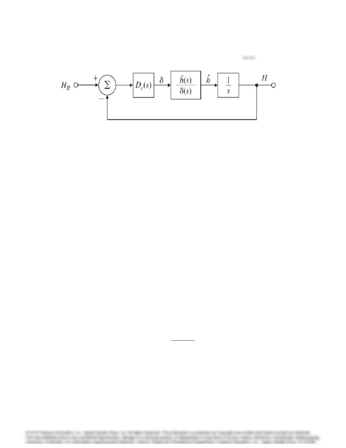
Figure 6.101: Control system for Problem 55
The autopilot receives from the altimeter an electrical signal proportional
to altitude. This signal is compared with a command signal (proportional
to the altitude selected by the pilot), and the difference provides an error
signal. The error signal is processed through compensation, and the result
is used to command the elevator actuators. A block diagram of this system
is shown in Fig. 6.103. You have been given the task of designing the
compensation. Begin by considering a proportional control law Dc(s) =
K.
(a) Use Matlab to draw a Bode plot of the open-loop system for Dc(s) =
K= 1.
(b) What value of Kwould provide a crossover frequency (i.e., where
jGj= 1) of 0.16 rad/sec?
(c) For this value of K, would the system be stable if the loop were
closed?
(d) What is the PM for this value of K?
(e) Sketch the Nyquist plot of the system, and locate carefully any points
where the phase angle is 180or the magnitude is unity.
(f) Use Matlab to plot the root locus with respect to K, and locate the
roots for your value of Kfrom part (b).
(g) What steady-state error would result if the command was a step
change in altitude of 1000 ft?
For parts (h)and (i), assume a compensator of the form
Dc(s) = KTDs+ 1
TDs+ 1:
(h) Choose the parameters K,T, and so that the crossover frequency
is 0.16 rad/sec and the PM is greater that 50. Verify your design by
superimposing a Bode plot of Dc(s)G(s)=K on top of the Bode plot
you obtained for part (a), and measure the PM directly.
6146 CHAPTER 6. THE FREQUENCY-RESPONSE DESIGN METHOD
(i) Use Matlab to plot the root locus with respect to Kfor the system
including the compensator you designed in part (h). Locate the roots
for your value of Kfrom part (h).
(j) Altitude autopilots also have a mode where the rate of climb is sensed
directly and commanded by the pilot.
i. Sketch the block diagram for this mode,
ii. define the pertinent G(s);
iii. design D(s)so that the system has the same crossover frequency
as the altitude hold mode and the PM is greater than 50
Solution :
The plant transfer function :
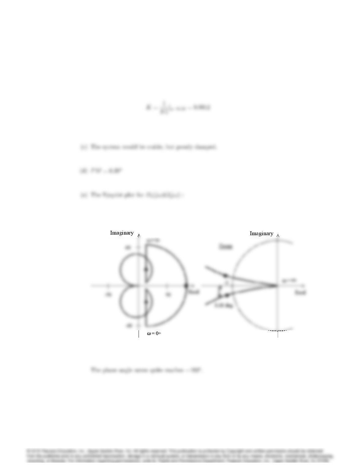
(a) See the Bode plot :
–40
–20
60
80
10
-4
10
-3
10
-2
10
-1
10
0
–135
0
Phase (deg)
Bode Diagram
Gm = Inf dB (at Inf rad/sec) , Pm = 0.386 deg (at 0.16 rad/sec)
Frequency (rad/sec)
–40
–20
60
80
10
-4
10
-3
10
-2
10
-1
10
0
–135
0
Phase (deg)
6147
(b) Since jGj= 865 at != 0:16,
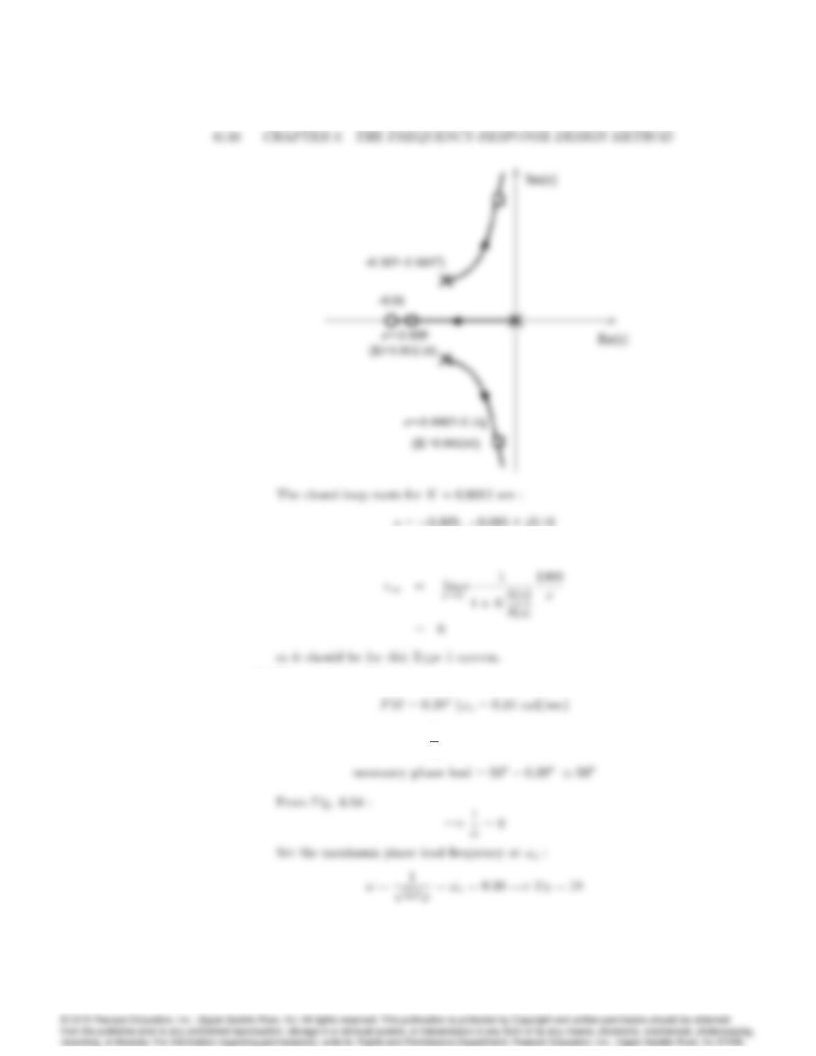
(f) See the Root locus :
(g) The steady-state error e1:
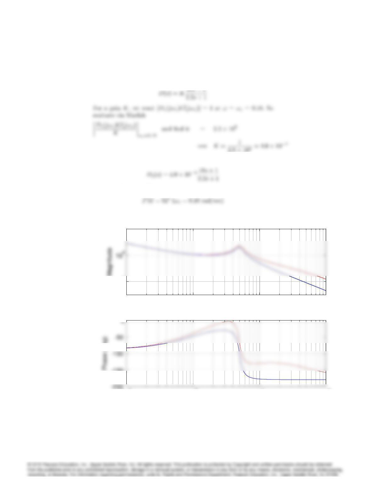
(h) Phase margin of the plant :
Necessary phase lead and 1
:
6149
so the compensation is
Therefore the compensation is :
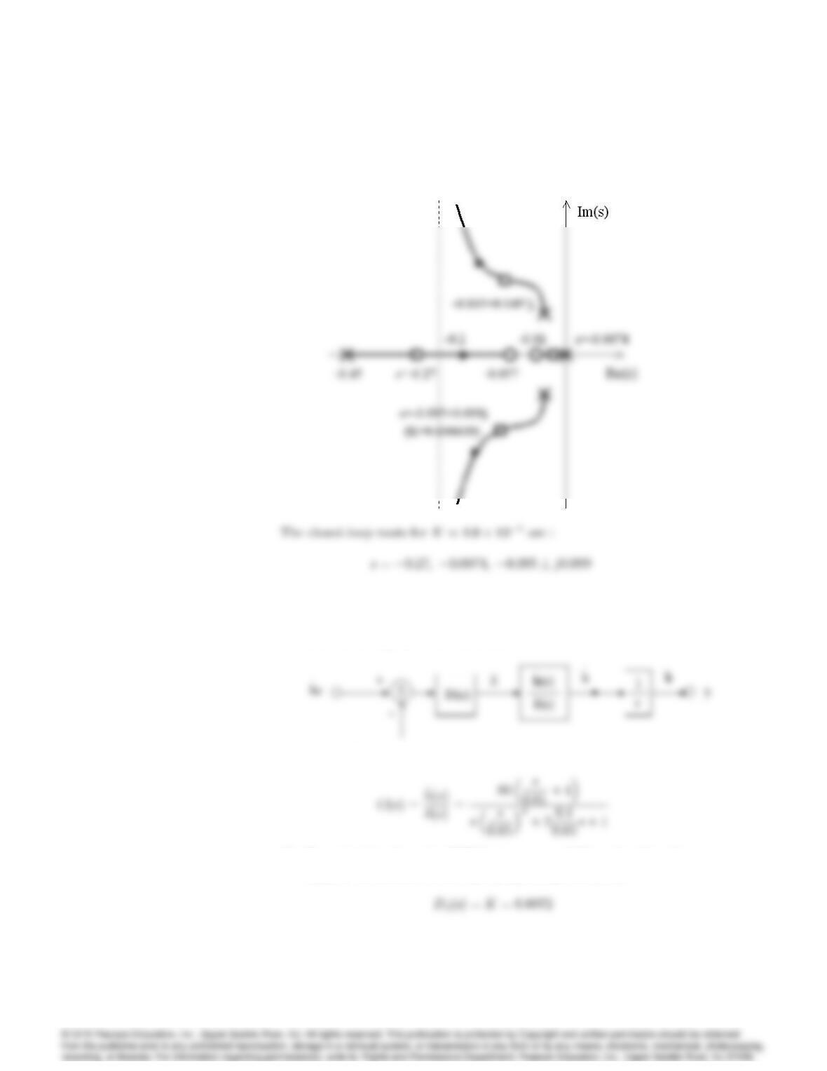
which results in the Phase margin :
10-3 10-2 10-1 100
102
106
ω (rad/sec)
Magnitude
Bode Diagrams
10-3 10-2 10-1 100
102
106
ω (rad/sec)
Magnitude
Bode Diagrams
10-3 10-2 10-1 100
-150
ω (rad/sec)
10-3 10-2 10-1 100
102
106
ω (rad/sec)
Magnitude
Bode Diagrams
10-3 10-2 10-1 100
102
106
ω (rad/sec)
Magnitude
Bode Diagrams
10-3 10-2 10-1 100
-150
ω (rad/sec)
6150 CHAPTER 6. THE FREQUENCY-RESPONSE DESIGN METHOD
(i) See the Root locus :
(j) In this case, the reference input and the feedback parameter are the
rate of climb.
i. The block diagram for this mode is :
ii. Define G(s)as :
iii. By evaluating the gain of G(s)at !=!c= 0:16;and setting K
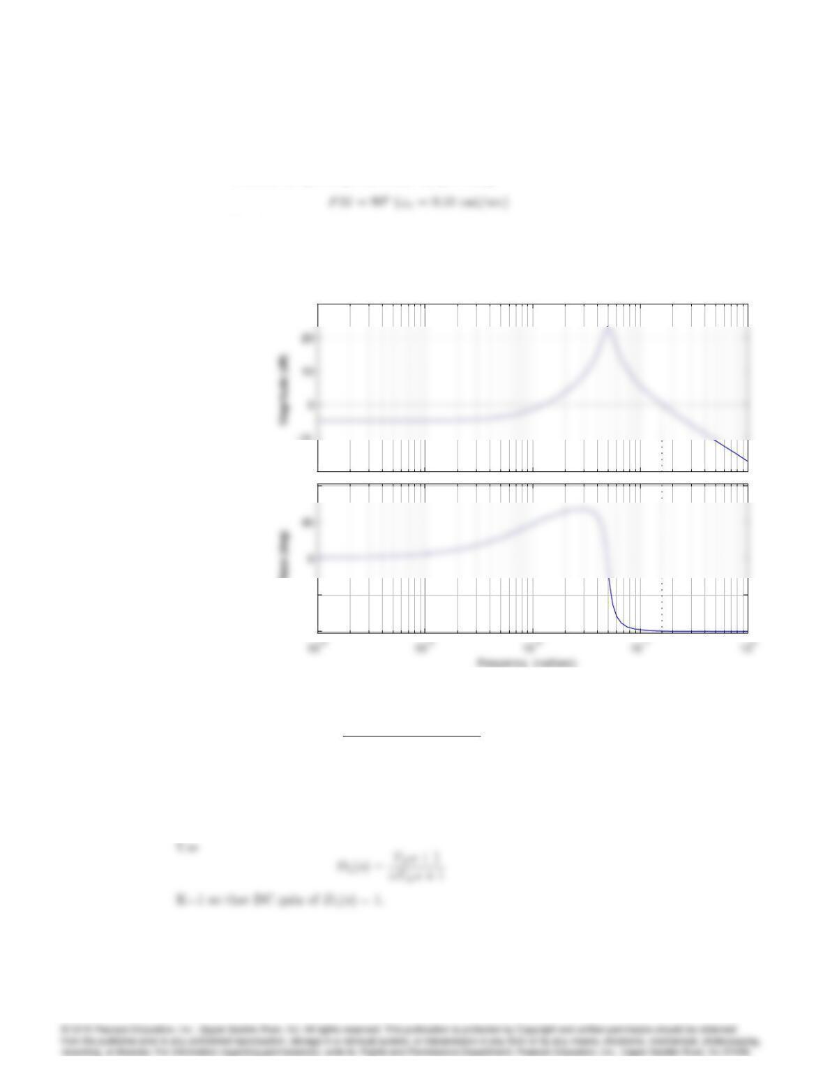
equal to its inverse, we see that proportional feedback :
6151
satisfies the given specifications by providing:
The Bode plot of the compensated system is :
–20
–10
30
–90
–45
90
Phase (deg)
Bode Diagram
Gm = Inf , Pm = 90.4 deg (at 0.16 rad/sec)
–20
–10
30
–90
–45
90
Phase (deg)
56. For a system with open-loop transfer function c
G(s) = 10
s[(s=1:4) + 1][(s=3) + 1];
design a lag compensator with unity DC gain so that PM 40. What is
the approximate bandwidth of this system?
Solution :
Lag compensation design :
6152 CHAPTER 6. THE FREQUENCY-RESPONSE DESIGN METHOD
(a) Find the stability margins of the plant without compensation by
plotting the Bode, find that:
(b) The lag compensation needs to lower the crossover frequency so that
aP M ‘40will result, so we see from the uncompensated Bode
that we need the crossover at about
(c) Pick the zero breakpoint of the lag to avoid in‡uencing the phase at
!=!c;new by picking it a factor of 20 below the crossover, so
(d) Choose :
Since Dc(j!)
=1
for ! >> 1
T, let
(e) Compensation :
(f) Stability margins of the compensated system :
6153
10-3 10-2 10-1 100101
100
ω (rad/sec)
Magnitude
Bode plot
-250
10-3 10-2 10-1 100101
100
ω (rad/sec)
Magnitude
Bode plot
10-3 10-2 10-1 100101
100
ω (rad/sec)
Magnitude
Bode plot
-250
10-3 10-2 10-1 100101
100
ω (rad/sec)
Magnitude
Bode plot
Compensated
57. For the ship-steering system in Problem 39,
(a) Design a compensator that meets the following specifications:
i. velocity constant Kv= 2,
ii. PM 50,
iii. unconditional stability (PM >0for all !!c, the crossover
frequency).
(b) For your final design, draw a root locus with respect to K, and indi-
cate the location of the closed-loop poles.
Solution :
The transfer function of the ship steering is
6154 CHAPTER 6. THE FREQUENCY-RESPONSE DESIGN METHOD
i. The phase margin of the uncompensated ship is
ii. The crossover frequency which provides P M ‘50is obtained
by looking at the uncompensated Bode plot below, where we see
that the crossover frequency needs to be lowered to
iii. Keep the zero of the lag a factor of 20 below the crossover to
keep the phase lag from the compensation from fouling up the
PM, so we find:
iv. Choose so that the gain reduction is achieved at crossover :
v. So the compensation is :
vi. Stability margins of the compensated system :
6155
(b) See the root locus. (Note that this is a zero degree root locus.)
The closed-loop roots for K= 2 are :
10-5 10-4 10-3 10-2 10-1 100
Frequency (rad/sec)
Bode Diagrams
10-5 10-4 10-3 10-2 10-1 100
Frequency (rad/sec)
Bode Diagrams
10-5 10-4 10-3 10-2 10-1 100
0
Frequency (rad/sec)
10-5 10-4 10-3 10-2 10-1 100
Frequency (rad/sec)
Bode Diagrams
10-5 10-4 10-3 10-2 10-1 100
Frequency (rad/sec)
Bode Diagrams
10-5 10-4 10-3 10-2 10-1 100
0
Frequency (rad/sec)
58. For a unity feedback system with
G(s) = 1
s(s
20 + 1)( s2
1002+ 0:5s
100 + 1) (2)
(a) A lead compensator is introduced with = 1=5and a zero at 1=TD=
20. How must the gain be changed to obtain crossover at !c=
31:6rad/sec, and what is the resulting value of Kv?
(b) With the lead compensator in place, what is the required value of K
for a lag compensator that will readjust the gain to a Kvvalue of
100?
(c) Place the pole of the lag compensator at 3.16 rad/sec, and determine
the zero location that will maintain the crossover frequency at !c=
31:6rad/sec. Plot the compensated frequency response on the same
graph.
(d) Determine the PM of the compensated design.
Solution :
(a) From a sketch of the asymptotes with the lead compensation (with
6157
(c) For a low frequency gain increase of 3.16, and the pole at 3.16 rad/sec,
the zero needs to be at 10 in order to maintain the crossover at
!c= 31:6rad/sec. So the lag compensator is
The Bode plots of the system before and after adding the lag com-
pensation are
100101102103
10-2
102
ω (rad/sec)
Bode Diagrams
100101102103
-400
0
ω (rad/sec)
100101102103
10-2
102
ω (rad/sec)
Bode Diagrams
100101102103
-400
0
ω (rad/sec)

59. Golden Nugget Airlines had great success with their free bar near the tail
of the airplane. (See Problem 5.40) However, when they purchased a much
larger airplane to handle the passenger demand, they discovered that there
was some ‡exibility in the fuselage that caused a lot of unpleasant yawing
motion at the rear of the airplane when in turbulence and was causing the
revelers to spill their drinks. The approximate transfer function for the
dutch roll mode (See Section 10.3.1) is
r(s)
r(s)=8:75(4s2+ 0:4s+ 1)
(s=0:01 + 1)(s2+ 0:24s+ 1)
where ris the airplane’s yaw rate and ris the rudder angle. In performing
a Finite Element Analysis (FEA) of the fuselage structure and adding
those dynamics to the dutch roll motion, they found that the transfer
function needed additional terms that re‡ected the fuselage lateral bending
that occurred due to excitation from the rudder and turbulence. The
revised transfer function is
r(s)
r(s)=8:75(4s2+ 0:4s+ 1)
(s=0:01 + 1)(s2+ 0:24s+ 1) 1
(s2
!2
b
+ 2s
!b+ 1)
where !bis the frequency of the bending mode (= 10 rad/sec) and is the
bending mode damping ratio (= 0:02). Most swept wing airplanes have
a “yaw damper” which essentially feeds back yaw rate measured by a rate
gyro to the rudder with a simple proportional control law. For the new
Golden Nugget airplane, the proportional feedback gain, K= 1;where
r(s) = Kr(s):(3)
(a) Make a Bode plot of the open-loop system, determine the PM and
GM for the nominal design, and plot the step response and Bode
magnitude of the closed-loop system. What is the frequency of the
lightly damped mode that is causing the difficulty?
(b) Investigate remedies to quiet down the oscillations, but maintain the
same low frequency gain in order not to affect the quality of the
dutch roll damping provided by the yaw rate feedback. Specifically,
investigate one at a time:
i. increasing the damping of the bending mode from = 0:02 to
= 0:04:(Would require adding energy absorbing material in
the fuselage structure)
ii. increasing the frequency of the bending mode from !b= 10
rad/sec to !b= 20 rad/sec. (Would require stronger and heavier
structural elements)

(3) with KDc(s)where
Dc(s) = 1
s=p+ 1:(4)
Pick pso that the objectionable features of the bending mode
are reduced while maintaining the PM 60o:
iv. adding a notch filter as described in Section 5.4.3. Pick the
frequency of the notch zero to be at !bwith a damping of =
0:04 and pick the denominator poles to be (s=100 + 1)2keeping
the DC gain of the filter = 1.
(c) Investigate the sensitivity of the two compensated designs above (iii
and iv) by determining the effect of a reduction in the bending mode
frequency of -10%. Specifically, re-examine the two designs by tab-
ulating the GM, PM, closed loop bending mode damping ratio and
resonant peak amplitude, and qualitatively describe the differences
in the step response.
(d) What do you recommend to Golden Nugget to help their customers
quit spilling their drinks? (Telling them to get back in their seats is
not an acceptable answer for this problem! Make the recommenda-
tion in terms of improvements to the yaw damper.)
Solution :
(a) The Bode plot of the open-loop system is :