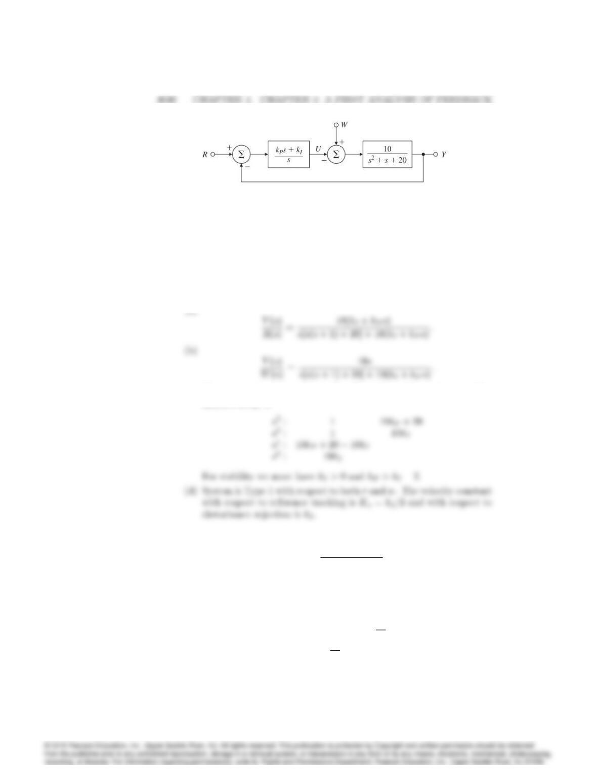
Figure 4.43: Control system for Problem 4.30
(c) What is the system type and error constant with respect to reference
tracking?
(d) What is the system type and error constant with respect to distur-
bance rejection?
Solution:
(a)
(c) The characteristic equation is s3+s2+ (10kP+ 20)s+ 10kI= 0. The
Routh’s array is
31. Consider the second-order plant with transfer function
G(s) = 1
(s+ 1)(5s+ 1):
and in a unity feedback structure.
(a) Determine the system type and error constant with respect to track-
ing polynomial reference inputs of the system for P [D=kP], PD
[D=kP+kDs], and PID [D=kP+kI
s+kDs]controllers. Let
kP= 19,kI= 0:5, and kD=4
19:
4041
(b) Determine the system type and error constant of the system with
respect to disturbance inputs for each of the three regulators in part
(a) with respect to rejecting polynomial disturbances w(t)at the
input to the plant.
(c) Is this system better at tracking references or rejecting disturbances?
Explain your response brie‡y.
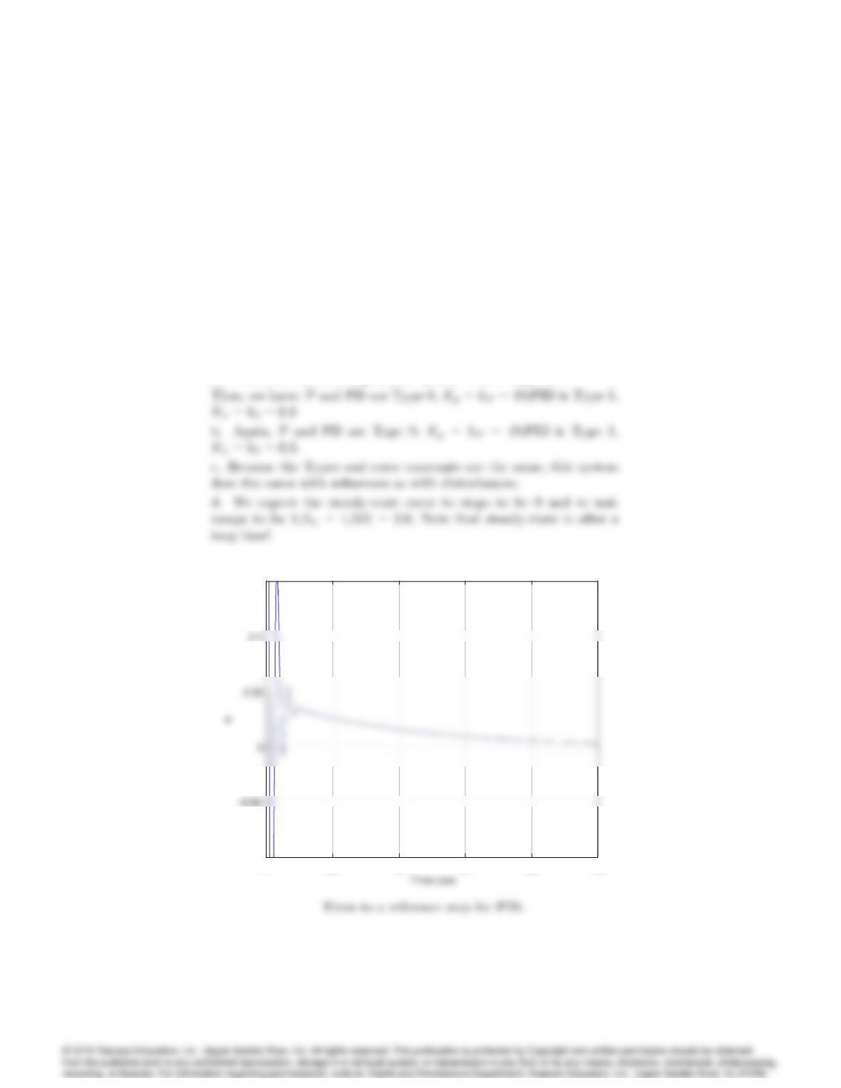
(d) Verify your results for parts (a) and (b) using Matlab by plot-
ting unit step and ramp responses for both tracking and disturbance
rejection.
Solution:
a. This plant has no pole at the origin and DC gain of 1 so, unless
the controller has such a pole, the system will be Type 0.
020 40 60 80 100
–0.1
0.15
err or for a reference step
020 40 60 80 100
–0.1
0.15
err or for a reference step
4042 CHAPTER 4. CHAPTER 4: A FIRST ANALYSIS OF FEEDBACK
020 40 60 80 100
0
0.2
0.4
0.8
1.4
1.8
2
Time (sec
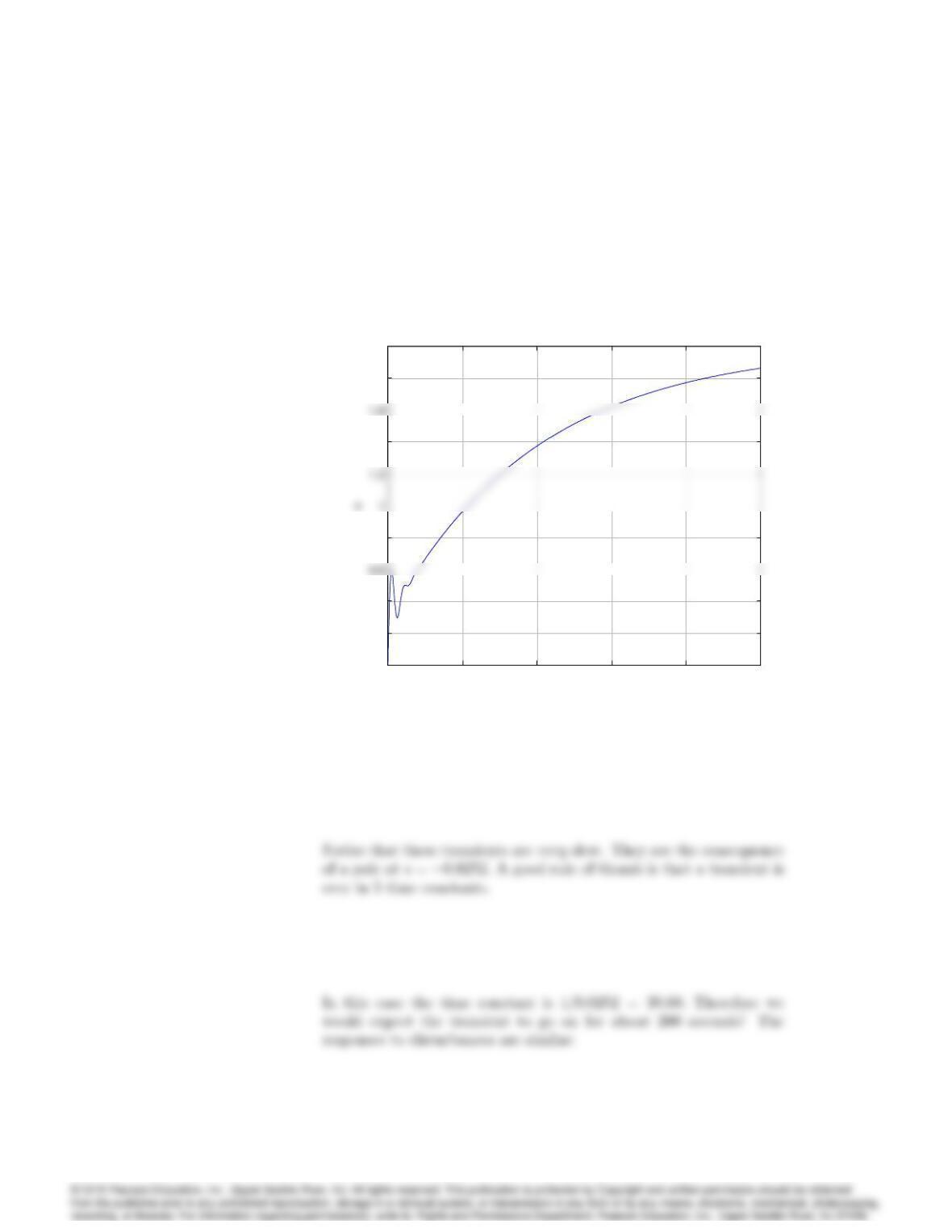
error for a reference ramp
020 40 60 80 100
0
0.2
0.4
0.8
1.4
1.8
2
Time (sec
error for a reference ramp
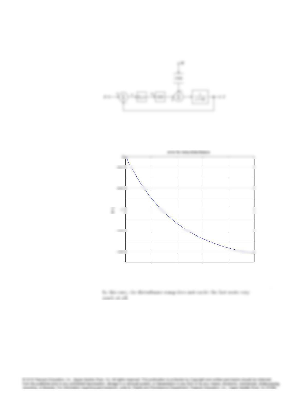
Error to a reference ramp for PID
4043
.
020 40 60 80 100
–0.07
–0.02
Time (sec)
020 40 60 80 100
–0.07
–0.02
Time (sec)
4044 CHAPTER 4. CHAPTER 4: A FIRST ANALYSIS OF FEEDBACK
Figure 4.44: D.C. Motor speed control block diagram for Problems 4.32 and
4.33
020 40 60 80 100
-2
–1.6
–1.2
–0.8
–0.4
Time (sec)
020 40 60 80 100
-2
–1.6
–1.2
–0.8
–0.4
Time (sec)
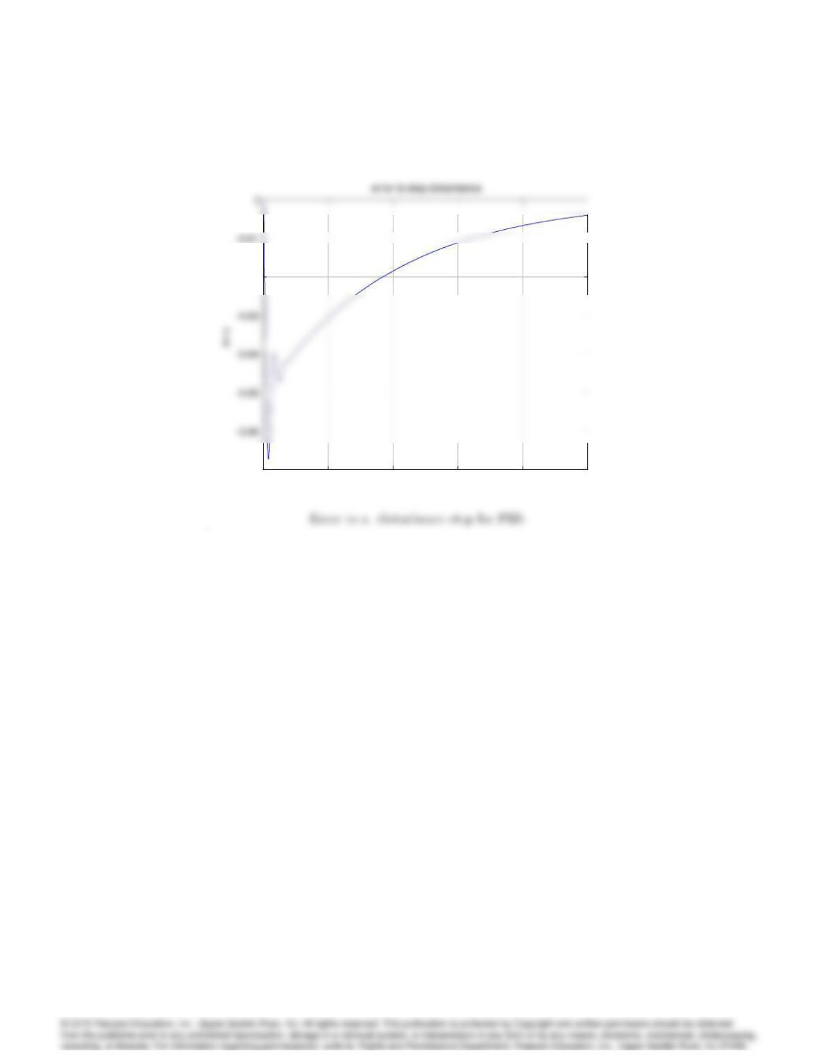
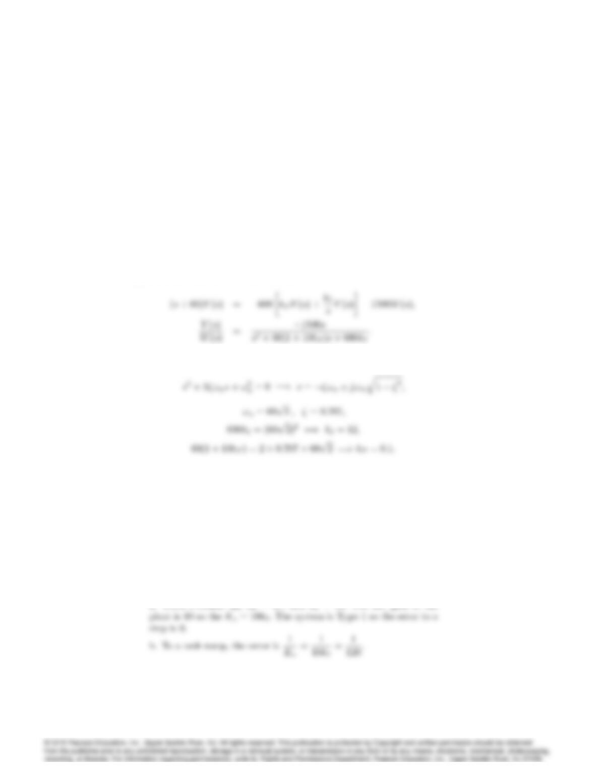
Error to a disturbance ramp for PID. .
32. The DC-motor speed control shown in Fig. 4.44 is described by the dif-
ferential equation
_y+ 60y= 600va1500w;
where yis the motor speed, vais the armature voltage, and wis the load
4045
torque. Assume the armature voltage is computed using the PI control law
va=kPe+kIZt
0
edt:
where e=ry:
(a) Compute the transfer function from Wto Yas a function of kPand
kI.
(b) Compute values for kPand kIso that the characteristic equation of
the closed-loop system will have roots at 60 60j.
Solution:
(a) Transfer function: Set R= 0;then E=Y
(b) For roots at 60 j60 : comparing to the standard form:
33. For the system in Problem 32, compute the following steady-state errors:
(a) to a unit-step reference input;
(b) to a unit-ramp reference input;
(c) to a unit-step disturbance input;
(d) for a unit-ramp disturbance input.
(e) Verify your answers to (a) and (d) using Matlab. Note that a ramp
response can be generated as a step response of a system modified
by an added integrator at the reference input.
Solution:
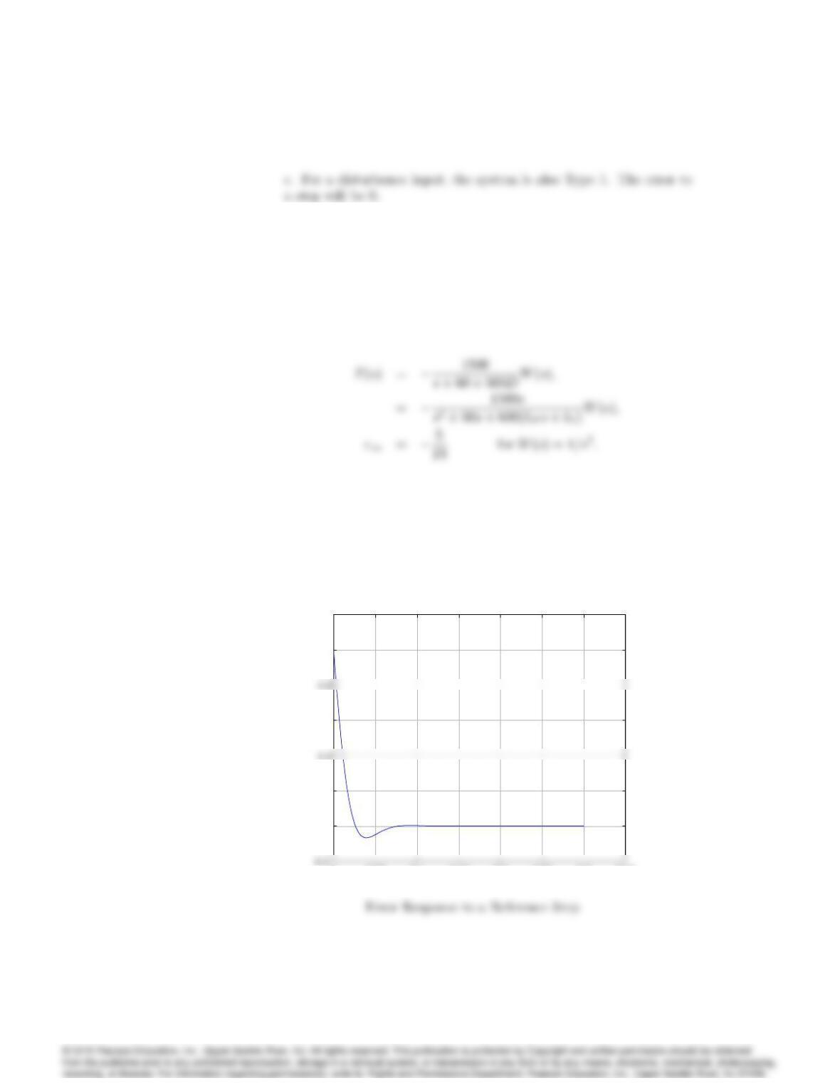
a. From Problem 33, kP= 0:1and kI= 12:The DC gain of the
4046 CHAPTER 4. CHAPTER 4: A FIRST ANALYSIS OF FEEDBACK
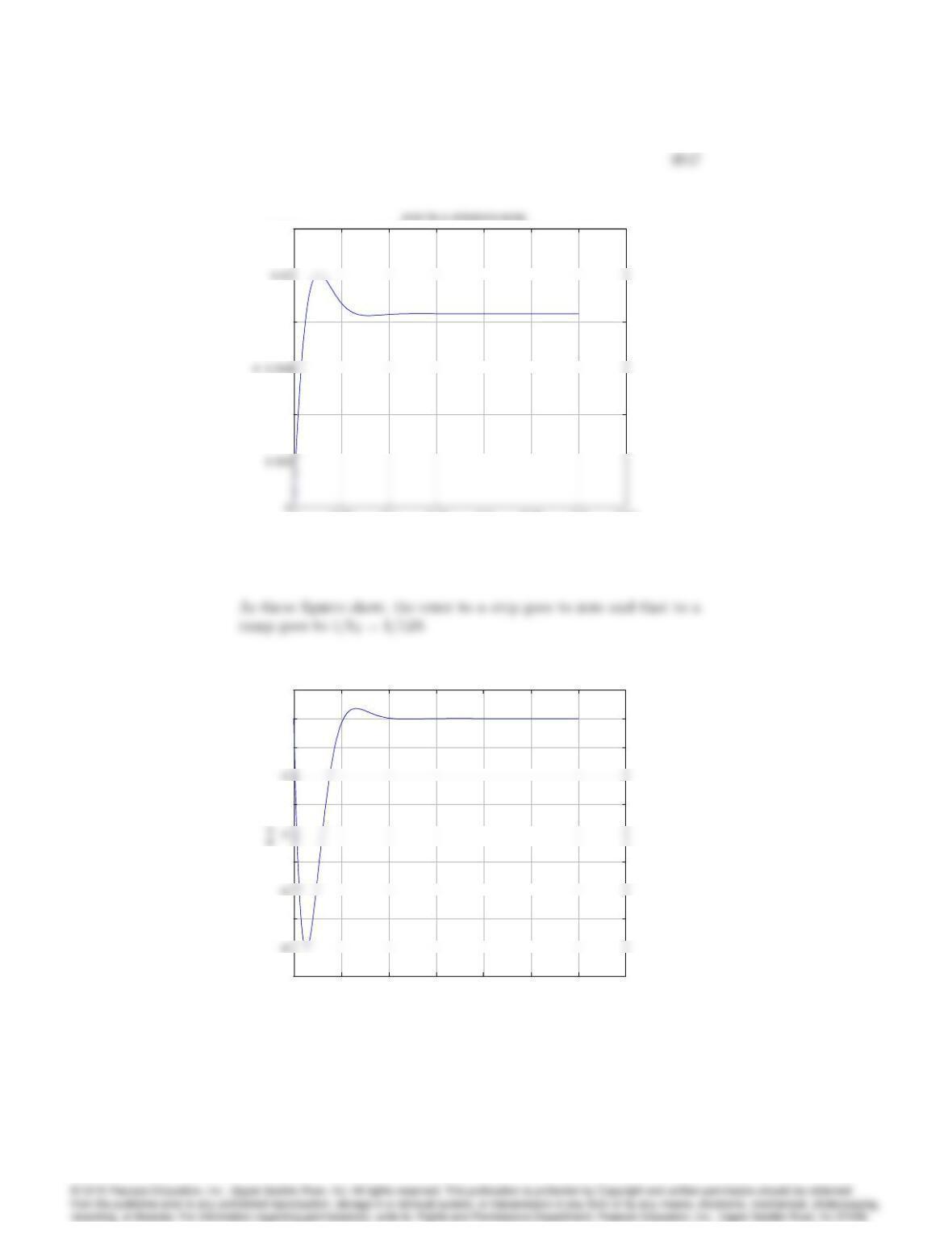
d. For a unit ramp disturbance input the error equals the output and
is given by
00.05 0.1 0.15 0.2 0.25 0.3 0.35
0
0.2
0.6
1
1.2
Time (sec)
e
error for a reference step
00.05 0.1 0.15 0.2 0.25 0.3 0.35
0
0.2
0.6
1
1.2
Time (sec)
e
error for a reference step
00.05 0.1 0.15 0.2 0.25 0.3 0.35
0.004
0.008
0.012
Time (sec)
00.05 0.1 0.15 0.2 0.25 0.3 0.35
0.004
0.008
0.012
Time (sec)
Error Response to a Reference Ramp
00.05 0.1 0.15 0.2 0.25 0.3 0.35
-9
-7
-5
-3
-1
0
1
Time (sec)
error to step disturbance
00.05 0.1 0.15 0.2 0.25 0.3 0.35
-9
-7
-5
-3
-1
0
1
Time (sec)
error to step disturbance
Error to a Disturbance Step
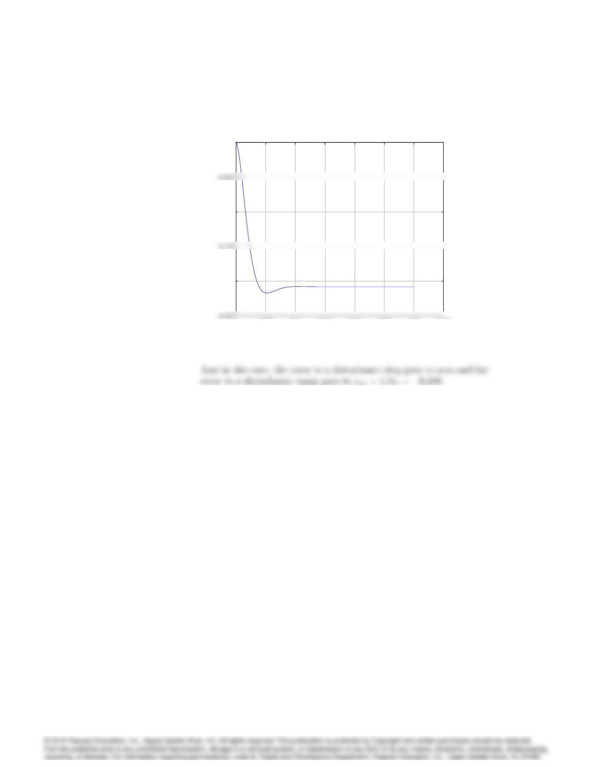
4048 CHAPTER 4. CHAPTER 4: A FIRST ANALYSIS OF FEEDBACK
00.05 0.1 0.15 0.2 0.25 0.3 0.35
–0.2
–0.1
0
Time (sec)
e=-y
error to ramp disturbance
00.05 0.1 0.15 0.2 0.25 0.3 0.35
–0.2
–0.1
0
Time (sec)
e=-y
Error to a Disturbance Ramp
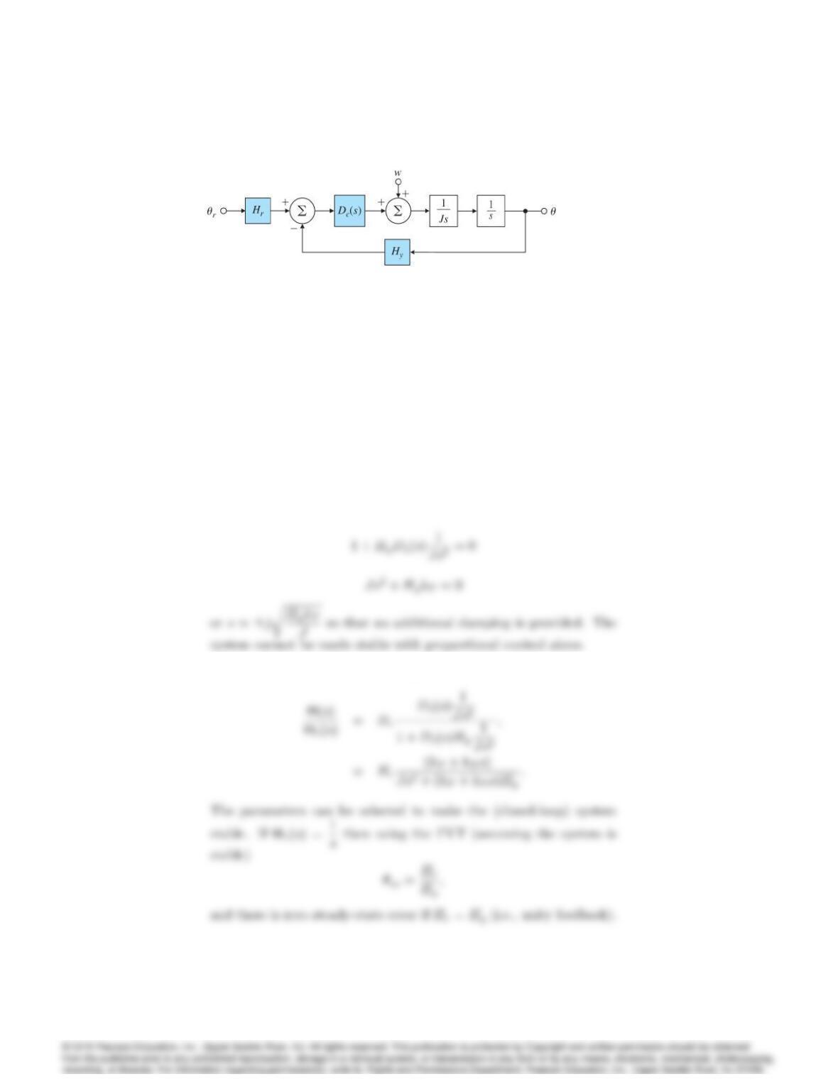
34. Consider the satellite-attitude control problem shown in Fig. 4.45 where
the normalized parameters are
J= 10 spacecraft inertia;N-m-sec2=rad
r= reference satellite attitude;rad.
= actual satellite attitude;rad.
Hy= 1 sensor scale;factor volts/rad.
Hr= 1 reference sensor scale factor;volts/rad.
w= disturbance torque:N-m
(a) Use proportional control, P, with Dc(s) = kP, and give the range of
values for kPfor which the system will be stable.
(b) Use PD control and let Dc(s) = (kP+kDs)and determine the system
type and error constant with respect to reference inputs.
(c) Use PD control, let Dc(s) = (kP+kDs)and determine the system
type and error constant with respect to disturbance inputs.
(d) Use PI control, let Dc(s) = (kP+kI=s), and determine the system
type and error constant with respect to reference inputs.
4049
Figure 4.45: Satellite attitude control
(e) Use PI control, let Dc(s) = (kP+kI=s), and determine the system
type and error constant with respect to disturbance inputs.
(f) Use PID control, let Dc(s) = (kP+kI=s +kDs)and determine the
system type and error constant with respect to reference inputs.
(g) Use PID control, let Dc(s) = (kP+kI=s +kDs)and determine the
system type and error constant with respect to disturbance inputs.
Solution:
(a) Dc(s) = kP; The characteristic equation is
(b) Steady-state error to reference steps.
4050 CHAPTER 4. CHAPTER 4: A FIRST ANALYSIS OF FEEDBACK
(c) Steady-state error to disturbance steps
(d) The characteristic equation is
(f) The characteristic equation with PID control is