
4000
Solutions Manual
.Chapter 4
7th Edition
Feedback Control of
Dynamic Systems
.
.
Gene F. Franklin
.
J. David Powell
.
Abbas Emami-Naeini
.
.
.
.
Assisted by:
H. K. Aghajan
H. Al-Rahmani
P. Coulot
P. Dankoski
S. Everett
R. Fuller
T. Iwata
V. Jones
F. Safai
L. Kobayashi
H-T. Lee
E. Thuriyasena
M. Matsuoka
Chapter 4
Chapter 4: A First Analysis
of Feedback
Problems and Solutions for Section 4.1: The Basic Equations of Con-
trol
1. If Sis the sensitivity of the unity feedback system to changes in the plant
transfer function and Tis the transfer function from reference to output,
show that S+T= 1:
Solution:
2. We define the sensitivity of a transfer function Gto one of its parameters
kas the ratio of percent change in Gto percent change in k.
SG
K=dG=G
dK=K =dln G
dln K=K
G
dG
dK :
The purpose of this problem is to examine the effect of feedback on sen-
sitivity. In particular, we would like to compare the topologies shown in
Fig. 4.24 for connecting three amplifier stages with a gain of Kinto a
single amplifier with a gain of 10.
(a) For each topology in Fig. 4.24, compute iso that if K= 10,Y=
10R.
4001
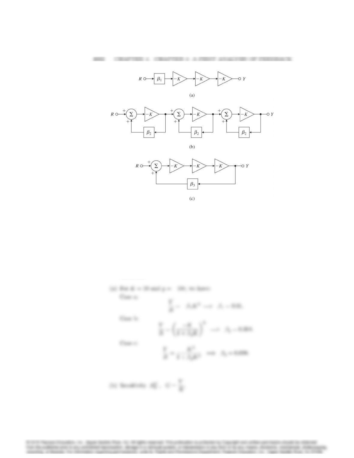
Figure 4.24: Three-amplifier topologies for Problem 4.2
(b) For each topology, compute SG
kwhen G=Y=R. [Use the respective
ivalues found in part (a).] Which case is the least sensitive?
(c) Compute the sensitivities of the systems in Fig. 4.24(b, c) to 2and
3. Using your results, comment on the relative need for precision in
sensors and actuators.
Solution:
4003
(c) Sensitivities w.r.t. feedback gains:
Case b:
3. Compare the two structures shown in Fig. 4.25 with respect to sensitivity
to changes in the overall gain due to changes in the amplifier gain. Use
the relation
S=dln F
dln K=K
F
dF
dK :
as the measure. Select H1and H2so that the nominal system outputs
satisfy F1=F2, and assume KH1>0.
Solution:
4004 CHAPTER 4. CHAPTER 4: A FIRST ANALYSIS OF FEEDBACK
4. A unity feedback control system has the open-loop transfer function
G(s) = A
s(s+a):
(a) Compute the sensitivity of the closed-loop transfer function to changes
in the parameter A.
(b) Compute the sensitivity of the closed-loop transfer function to changes
in the parameter a.
(c) If the unity gain in the feedback changes to a value of 6= 1, compute
the sensitivity of the closed-loop transfer function with respect to .
Solution:
(a)
A
s(s+a)
(b)
dT
da =sA
(s2+as +A)2:
4005
(c) In this case,
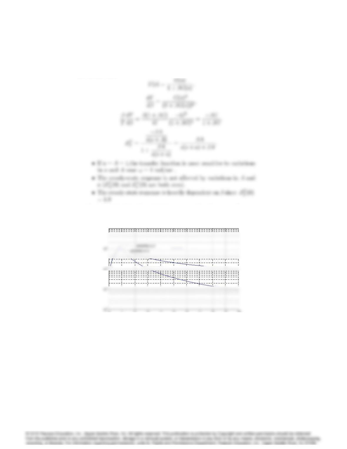
See attached plots of sensitivities versus radian frequency for a=
A= 1:0:
0 1 2 3 4 5 6 7 8 9 10
101
sens itivity to beta
Sensitivity function frequency response
Frequency (rad/sec)
5. Compute the equation for the system error for the filtered feedback system
shown in Fig. 4.5.
Solution:
For this figure, the equation for the output is:
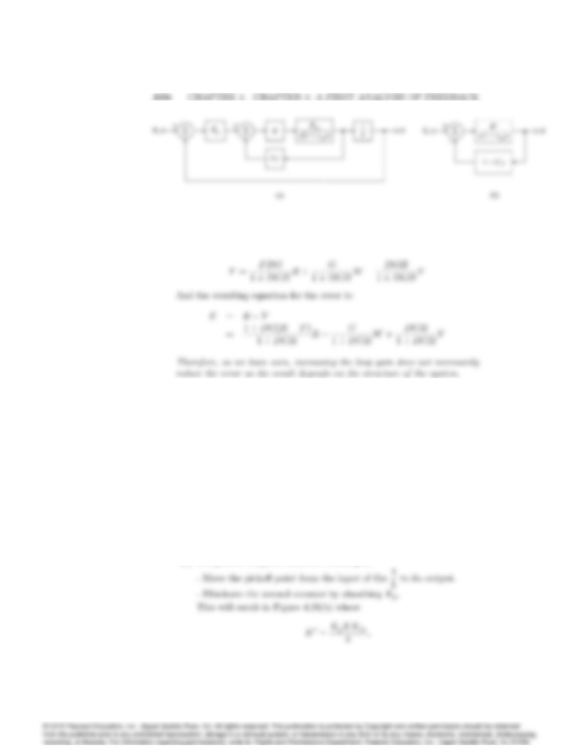
Figure 4.26: Control system for Problem 4.6
Problems and Solutions for Section 4.2: Control of Steady-State
Error
6. Consider the DC-motor control system with rate (tachometer) feedback
shown in Fig. 4.26(a).
(a) Find values for K0and k0
tso that the system of Fig. 4.26(b) has the
same transfer function as the system of Fig. 4.26(a).
(b) Determine the system type with respect to tracking rand compute
the system Kvin terms of parameters K0and k0
t.
(c) Does the addition of tachometer feedback with positive ktincrease
or decrease Kv?
Solution:
(a) Using block diagram reduction techniques:
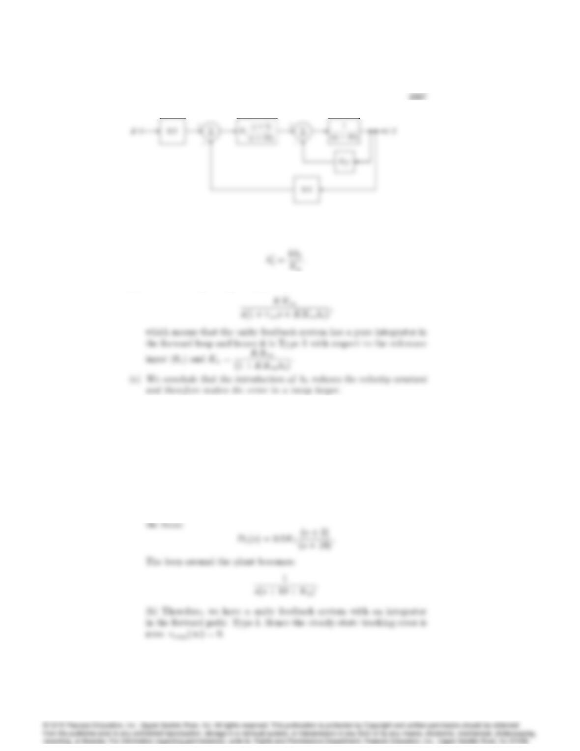
Figure 4.27: Closed-loop system for Problem 4.7
(b) The inner-loop in Fig. 4.26(a) may be reduced to
7. A block diagram of a control system is shown in Fig. 4.27.
(a) If Ris a step function and the system is closed-loop stable, what is
the steady-state tracking error?
(b) What is the system type?
(c) What is the steady-state error to a ramp velocity 5:0if K2= 2 and
K1is adjusted to give a system step overshoot of 17%?
Solution:
(a) Using conversion to unity feedback rule, we obtain a controller of
4008 CHAPTER 4. CHAPTER 4: A FIRST ANALYSIS OF FEEDBACK
(c)
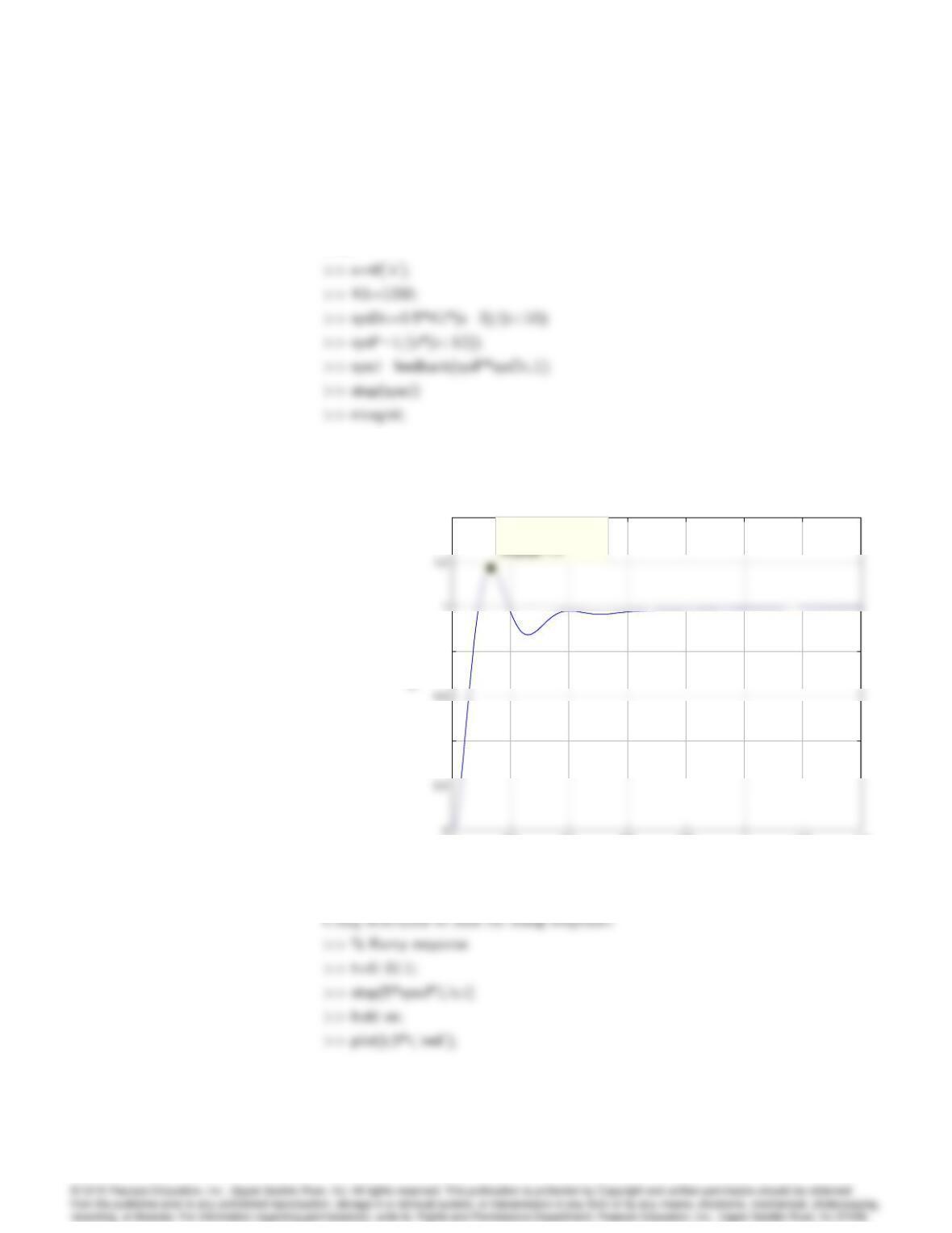
Using MATLAB, we find that a value of K1= 1200 results in Mp=
17%:
ch4 Prob 4p8
Sol
6:pdf
00.2 0.4 0.6 0.8 11.2 1.4
0.4
0.8
1.4
St ep Response
Time (seconds)
00.2 0.4 0.6 0.8 11.2 1.4
0.4
0.8
1.4
System: syscl
Time (seconds): 0.131
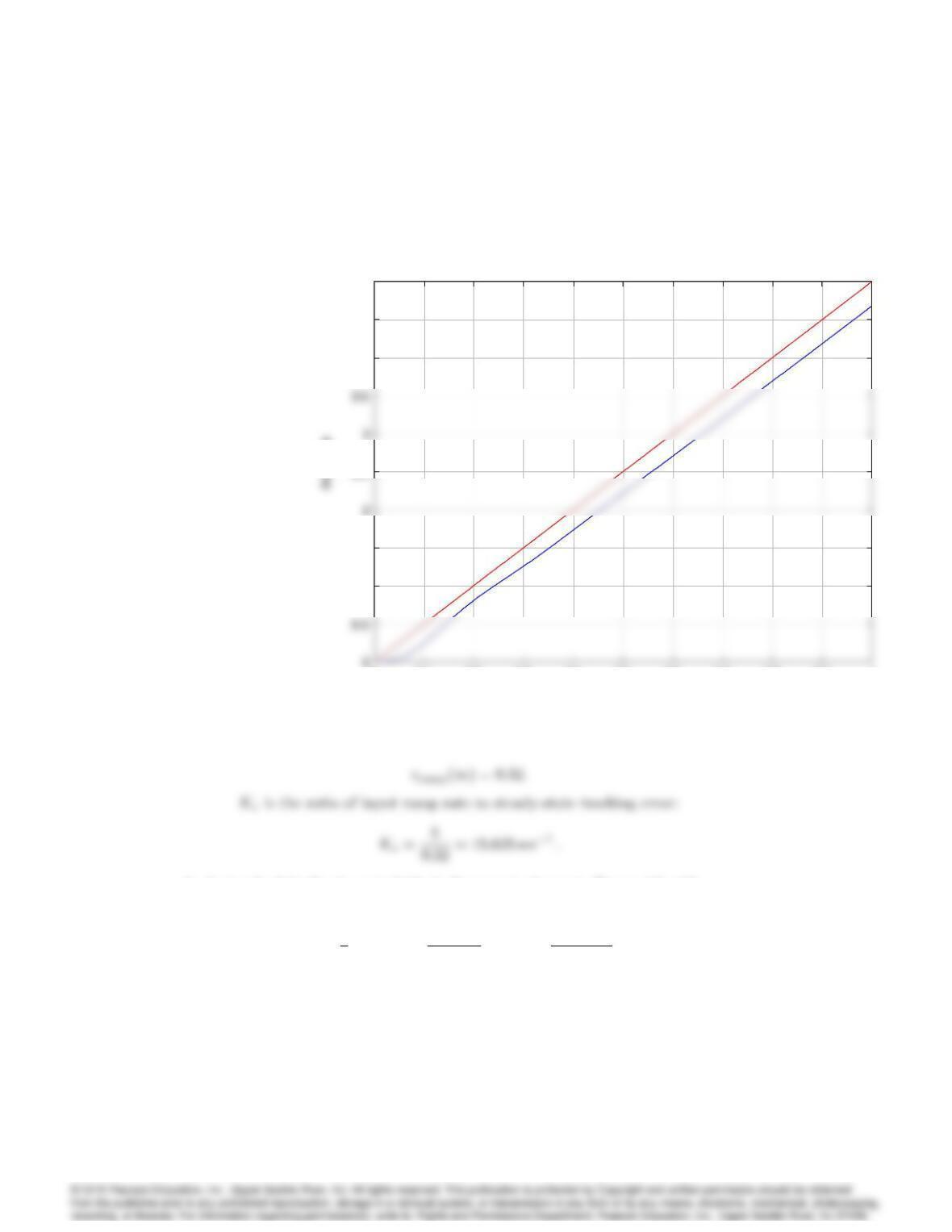
Step response for Problem 4.7.
4009
ch4 Prob 8 part
b
7:pdf
00.1 0.2 0.3 0.4 0.5 0.6 0.7 0.8 0.9 1
1
1.5
2.5
4
4.5
5
Step Response
Time ( seconds)
00.1 0.2 0.3 0.4 0.5 0.6 0.7 0.8 0.9 1
1
1.5
2.5
4
4.5
5
Ramp response for Problem 4.7 with a slope of size 5.
8. A standard feedback control block diagram is shown in Figure 4.5 with
the values
G(s) = 1
s;Dcl(s) = 2(s+ 1)
s;H(s) = 100
(s+ 100):
(a) Let W= 0 and compute the transfer function from Rto Y.
(b) Let R= 0 and compute the transfer function from Wto Y.
(c) What is the tracking error if Ris a unit step input and W0?
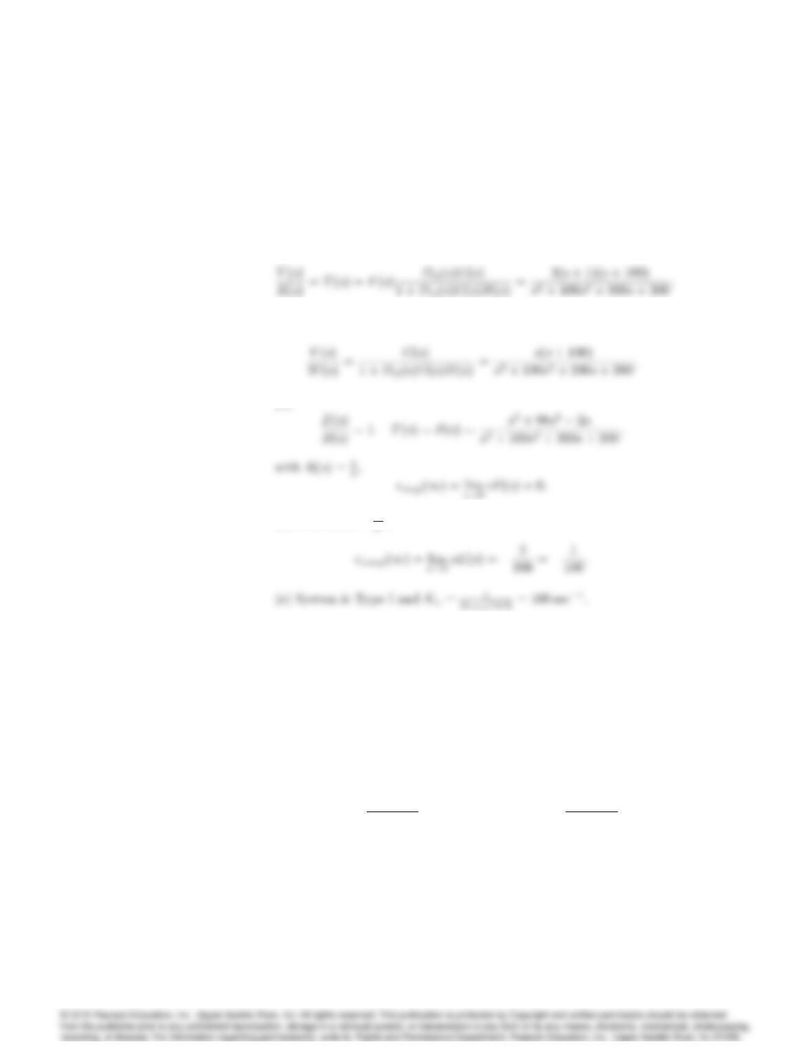
4010 CHAPTER 4. CHAPTER 4: A FIRST ANALYSIS OF FEEDBACK
(d) What is the tracking error if Ris a unit ramp input and W0?
(e) What is the system type and the corresponding error coefficient?
Solution:
(a)
(b)
(c)
(d) with R(s) = 1
9. A generic negative feedback system with non-unity transfer function in
the feedback path is shown in Figure 4.5.
(a) Find the steady-state tracking error for this system to a ramp refer-
ence input.
(b) If G(s)has a single pole at the origin in the s-plane, what is the
requirement on H(s)such that the system will remain a Type I sys-
tem?
(c) Suppose,
G(s) = 1
s(s+ 1)2;Dcl(s) = 0:73; H(s) = 2:75s+ 1
0:36s+ 1:
showing a lead compensation in the feedback path. What is the value
of the velocity error coefficient, Kv?
Solution:
4011
(a)
Y(s)
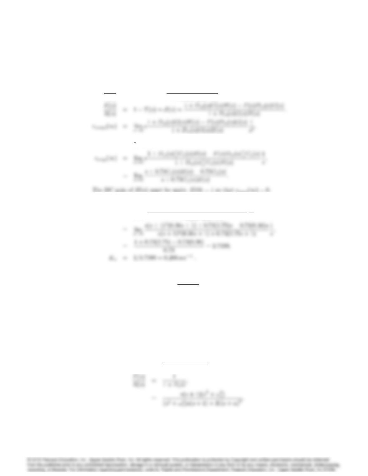
R(s)=T(s) = F(s)Dcl(s)G(s)
1 + Dcl(s)G(s)H(s):
(b) Let G(s) = 1
sG1(s);
(c)
eramp (1) = lim
s!0s1 + Dcl(s)G(s)H(s)F(s)Dcl(s)G(s)
1 + Dcl(s)G(s)H(s)
1
s2;
10. Consider the system shown in Fig. 4.28, where
Dc(s) = K(s+)2
s2+!2
o
:
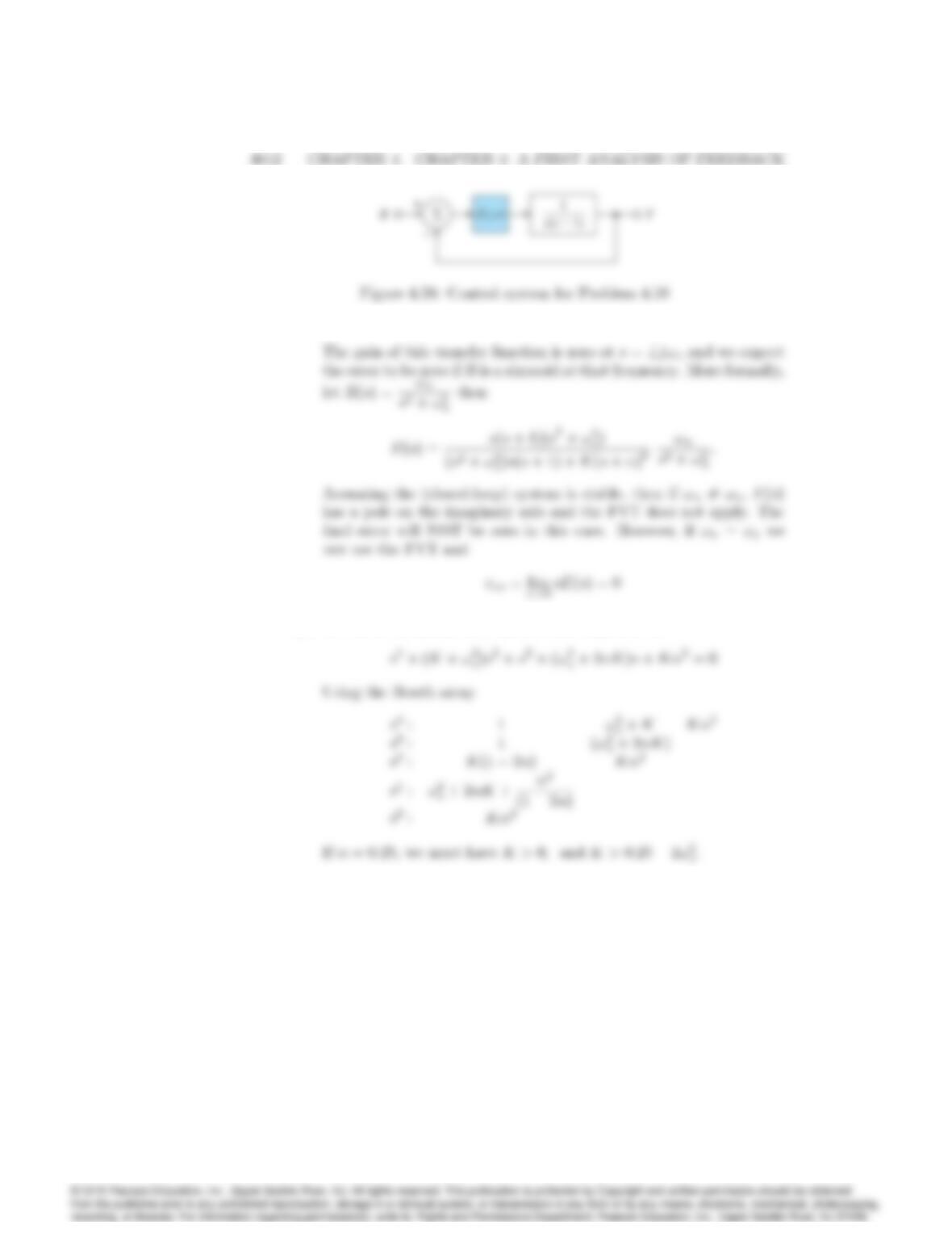
(a) Prove that if the system is stable, it is capable of tracking a sinusoidal
reference input r= sin !otwith zero steady-state error. (Look at the
transfer function from Rto Eand consider the gain at !o:)
(b) Use Routh’s criterion to find the range of Ksuch that the closed-loop
system remains stable if !o= 1 and = 0:25:
Solution:
(a)
Dc(s)G(s) = K(s+)2
(s2+!2
o)s(s+ 1);
(b) To test for stability, the characteristic equation is,
11. Consider the system shown in Fig. 4.29 which represents control of the
angle of a pendulum that has no damping.
(a) What condition must Dc(s)satisfy so that the system can track a
ramp reference input with constant steady-state error?
(b) For a transfer function Dc(s)that stabilizes the system and satisfies
the condition in part (a), find the class of disturbances w(t)that the
system can reject with zero steady-state error.
Solution:
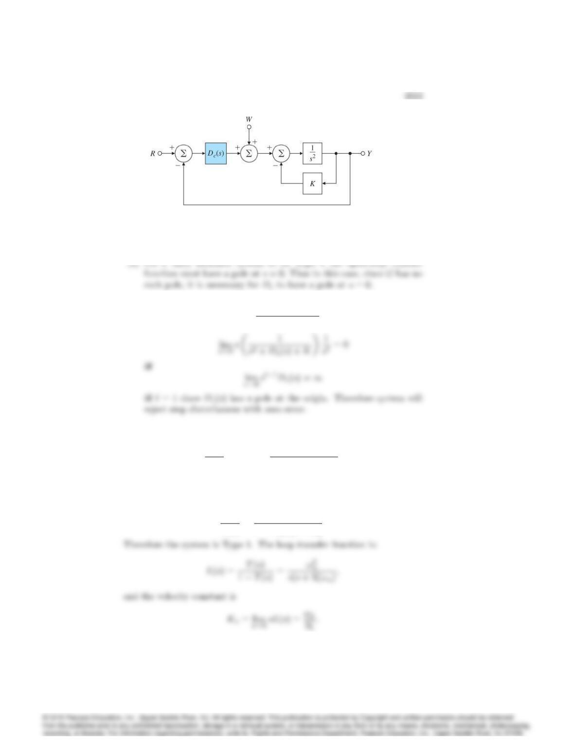
Figure 4.29: Control system for Problem 4.11
(b)
Y(s) = 1
s2+Dc(s) + KW(s)
12. A unity feedback system has the overall transfer function
Y(s)
R(s)=T(s) = !2
n
s2+ 2!ns+!2
n
:
Give the system type and corresponding error constant for tracking poly-
nomial reference inputs in terms of and !n.
Solution: E(s)
R(s)=s2+ 2!ns
s2+ 2!ns+!2
n
:
13. Consider the second-order system
G(s) = 1
s2+ 2s + 1 :
We would like to add a transfer function of the form Dc(s) = K(s+a)=(s+
b)in series with G(s)in a unity-feedback structure.
(a) Ignoring stability for the moment, what are the constraints on K; a,
and bso that the system is Type 1?
(b) What are the constraints placed on K,a, and bso that the system
is both stable and Type 1?
(c) What are the constraints on aand bso that the system is both Type
1 and remains stable for every positive value for K?
Solution:
(a) In a unity feedback structure, the error is 1=(1 + GDc)and, as we
(b) To assure stability, all poles of the closed loop must be in the left half
plane, for which the criterion is by Routh. Thus the characteristic
(c) If we assume that > 0and, for this part, that a > 0also, the
requirements can be reduced to
Extra credit: work out the case for < 0:Note to the Instructor:
you might come back to this problem in Chapter 5 and verify this
point using the rule of asymptotes.
14. Consider the system shown in Fig. 4.30(a).
(a) What is the system type? Compute the steady-state tracking error
due to a ramp input r(t) = rot1(t).
(b) For the modified system with a feed forward path shown in Fig. 4.30(b),
give the value of Hfso the system is Type 2 for reference inputs and
compute the Kain this case.
(c) Is the resulting Type 2 property of this system robust with respect
to changes in Hf?i.e., will the system remain Type 2 if Hfchanges
slightly?
Solution:
(a) System is Type 1 since it is unity feedback and has a pole at
s= 0in the forward path. Also,
4016 CHAPTER 4. CHAPTER 4: A FIRST ANALYSIS OF FEEDBACK
(b)
Y(s) = A
s(s + 1)U(s);
To get zero steady-state error with respect to a ramp, the numerator
in the above equation must have a factor s2. For this to happen, let
15. A controller for a satellite attitude control with transfer function G= 1=s2
has been designed with a unity feedback structure and has the transfer
function Dc(s) = 10(s+ 2)
s+ 5 :
(a) Find the system type for reference tracking and the corresponding
error constant for this system.
(b) If a disturbance torque adds to the control so that the input to the
process is u+w; what is the system type and corresponding error
constant with respect to disturbance rejection?
Solution:
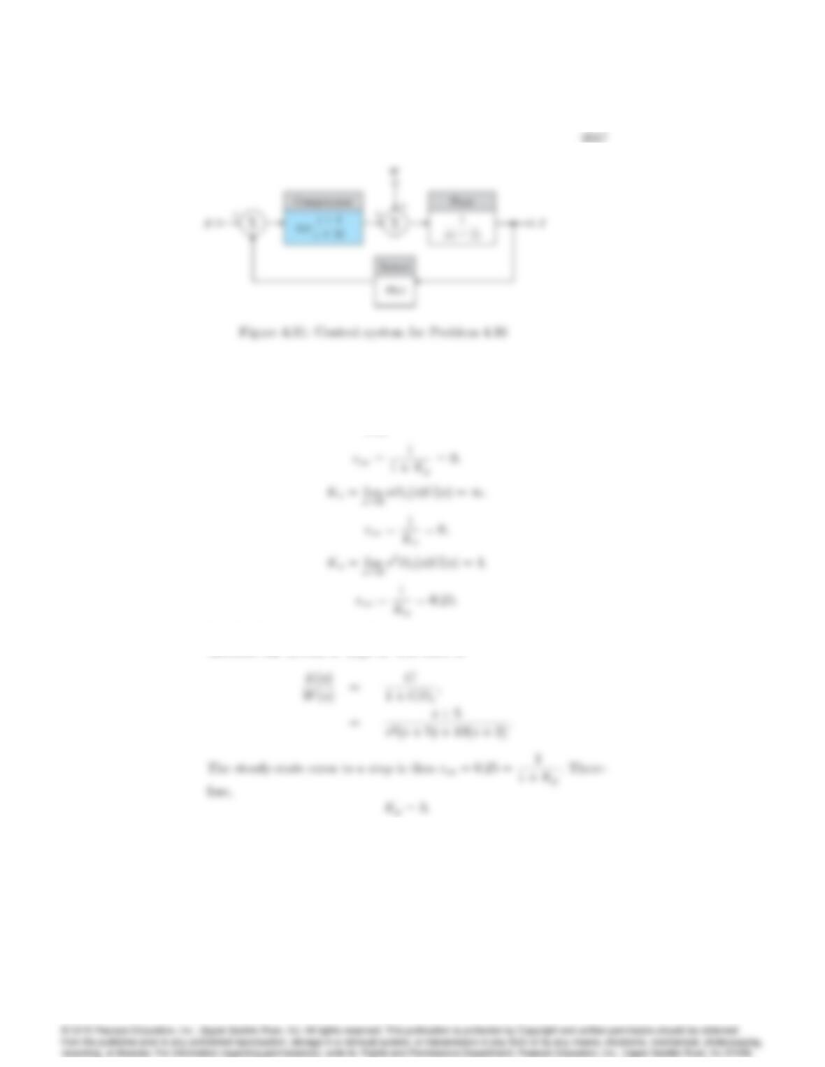
(a) There are two poles at s= 0 so the system is Type 2 and the error
constants are:
Kp= lim
s!0Dc(s)G(s) = 1:
(b) For the disturbance input, the poles at s= 0 are after the input and
therefore the system is Type 0. The error is
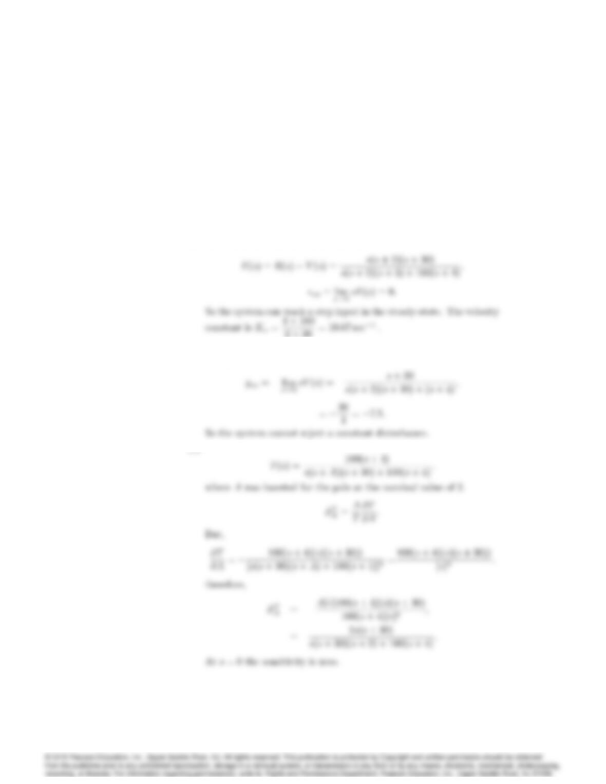
16. A compensated motor position control system is shown in Fig. 4.31. As-
sume that the sensor dynamics are H(s) = 1.
(a) Can the system track a step reference input rwith zero steady-state
error? If yes, give the value of the velocity constant.
4018 CHAPTER 4. CHAPTER 4: A FIRST ANALYSIS OF FEEDBACK
(b) Can the system reject a step disturbance wwith zero steady-state
error? If yes, give the value of the velocity constant.
(c) Compute the sensitivity of the closed-loop transfer function to changes
in the plant pole at 2.
(d) In some instances there are dynamics in the sensor. Repeat parts (a)
to (c) for H(s) = 20=(s+20) and compare the corresponding velocity
constants.
Solution:
(a) The system is Type 1 with H(s) = 1.
230 = 10:67 sec1:
(b) The system is Type 0 with respect to the disturbance and has the
steady-state error.
(c)
4019
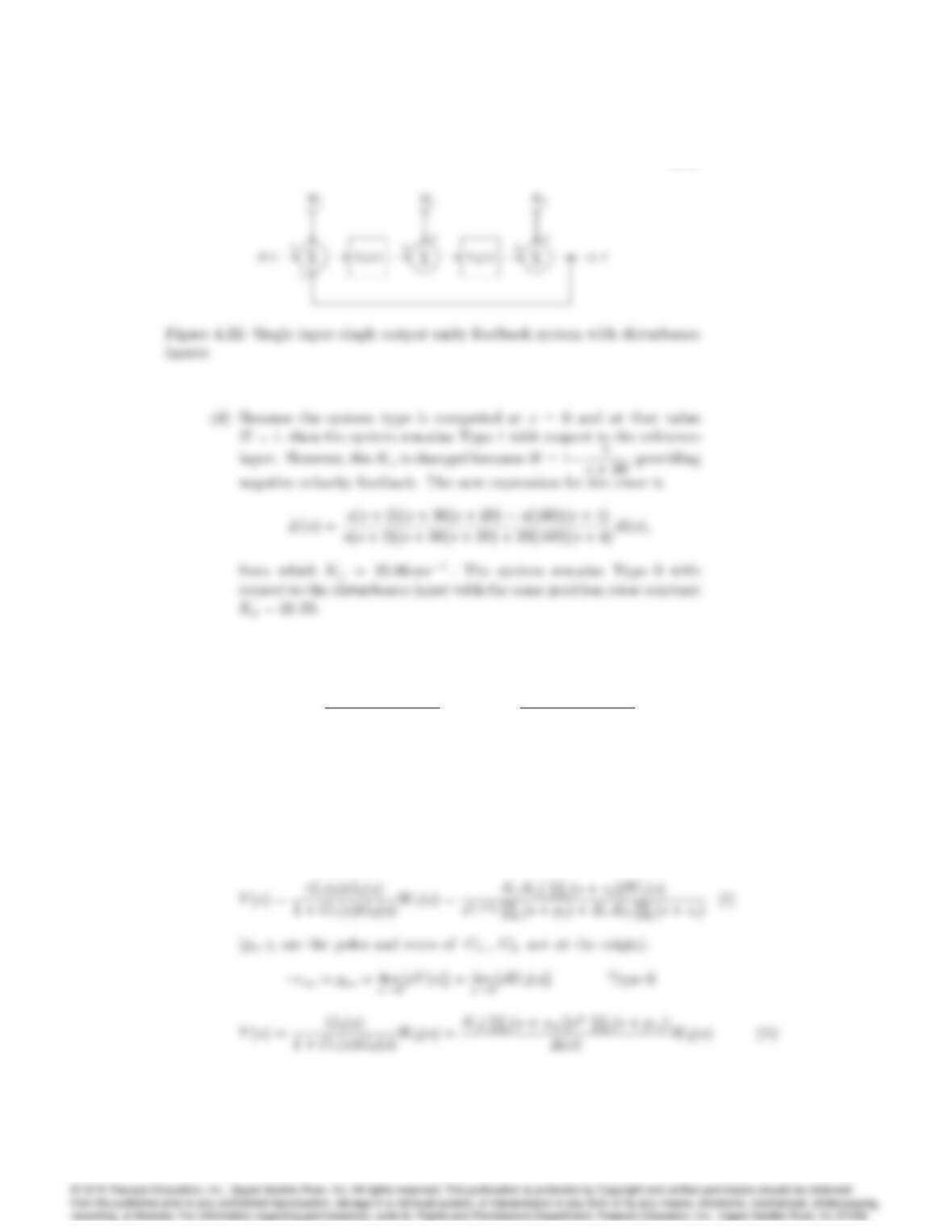
17. The general unity feedback system shown in Fig. 4.32 has disturbance
inputs w1,w2and w3and is asymptotically stable. Also,
G1(s) = K1Qm1
i=1(s+z1i)
sl1Qm1
i=1(s+p1i); G2(s) = K2Qm1
i=1(s+z2i)
sl2Qm1
i=1(s+p2i):
(a) Show that the system is of Type 0, Type l1, and Type (l1+l2)with
respect to disturbance inputs w1,w2, and w3respectively.
Solution:
(a)