3020 CHAPTER 3. DYNAMIC RESPONSE
using the atan2 command in Matlab, and
also using the atan2 command in Matlab.
So the inverse Laplace transform of F(s)is:
(g) Follows from Problem 5 (c), or expand in series,
Alternatively, let us assume
3021
9. Solve the following ordinary differential equations using Laplace trans-
forms:
(a) •y(t) + _y(t) + 3y(t) = 0; y(0) = 1;_y(0) = 2
(b) •y(t)2 _y(t) + 4y(t) = 0; y(0) = 1;_y(0) = 2
(c) •y(t) + _y(t) = sin t;y(0) = 1;_y(0) = 2
(d) •y(t) + 3y(t) = sin t;y(0) = 1;_y(0) = 2
(e) •y(t) + 2 _y(t) = et;y(0) = 1;_y(0) = 2
(f) •y(t) + y(t) = t;y(0) = 1;_y(0) = 1
Solution:
(a)
Using Table A.2 entries #19 and #20,
3022 CHAPTER 3. DYNAMIC RESPONSE
(b)
•y(t)2 _y(t) + 4y(t) = 0; y(0) = 1;_y(0) = 2:
(c)
•y(t) + _y(t) = sin t;y(0) = 1;_y(0) = 2
s2Y(s)sy (0) _y(0) + sY (s)y(0) = 1
3023
(d)
•y(t) + 3y(t) = sin t;y(0) = 1;_y(0) = 2;
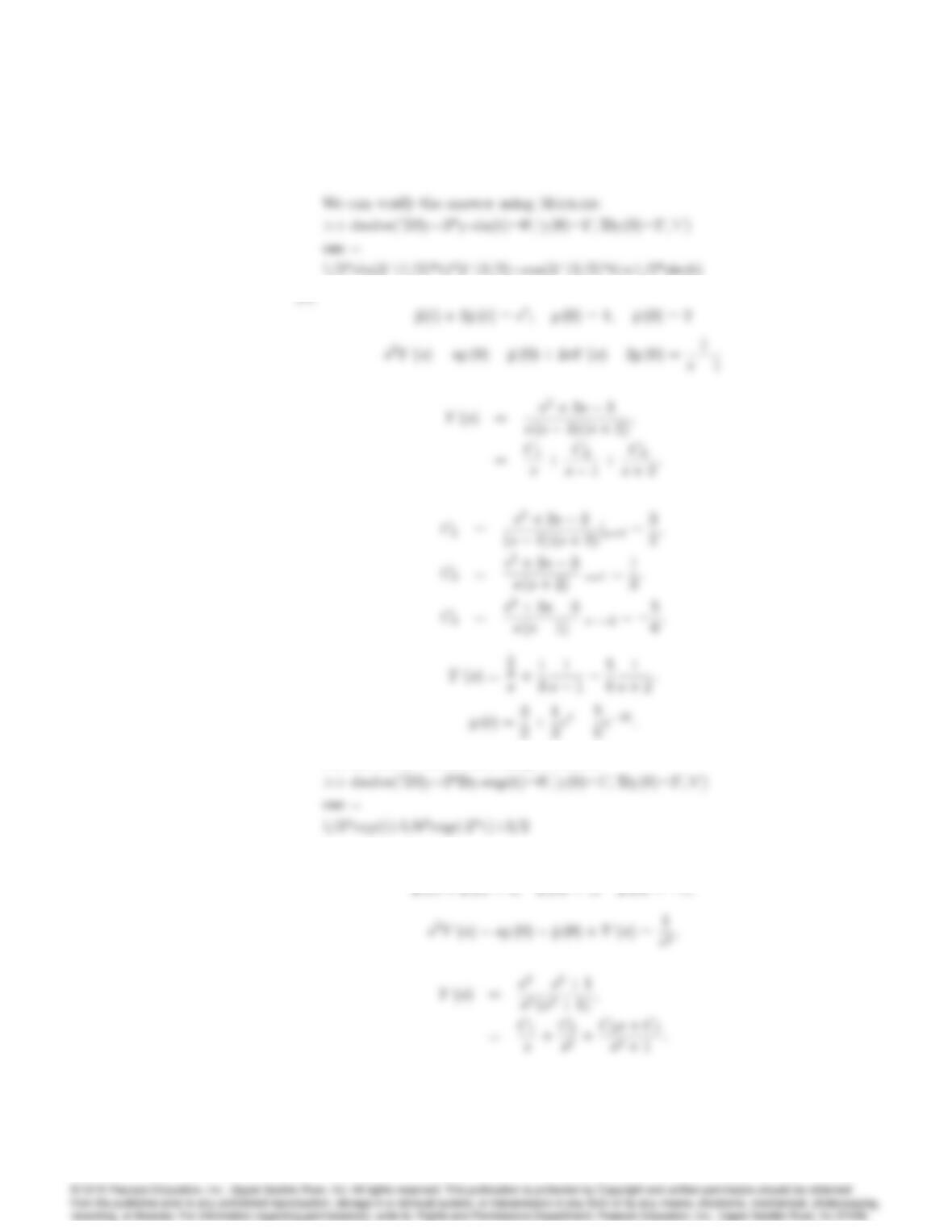
Match coefficients of like powers of s:
3024 CHAPTER 3. DYNAMIC RESPONSE
(e)
We can verify the answer using Matlab:
(f) Using the results from Appendix A,
•y(t) + y(t) = t;y(0) = 1;_y(0) = 1;
3025
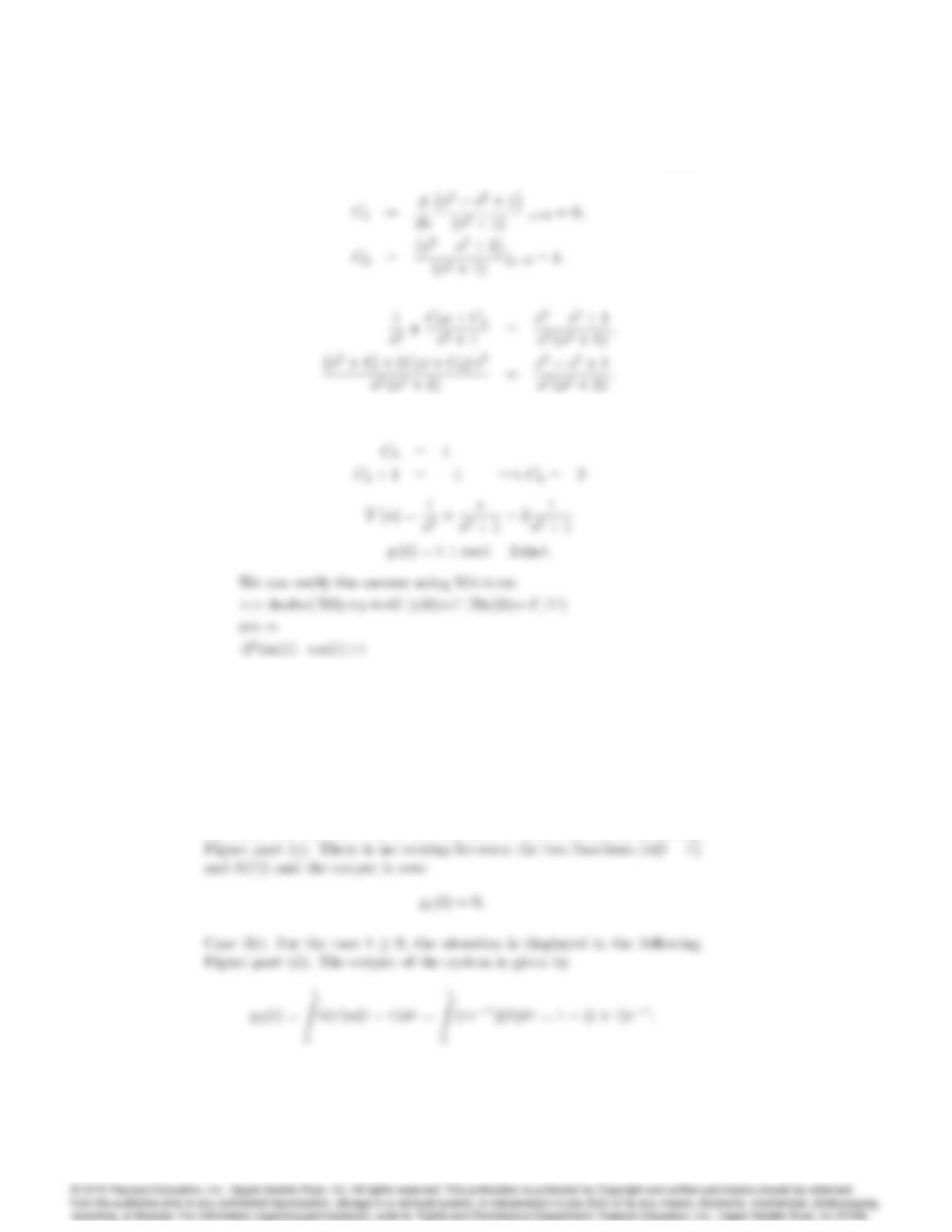
Match coefficients of like powers of s:
10. Using the convolution integral, find the step response of the system whose
impulse response is given below and shown in Figure 3.44:
h(t) = tett0
0t < 0:
Solution: There are only two cases to consider.
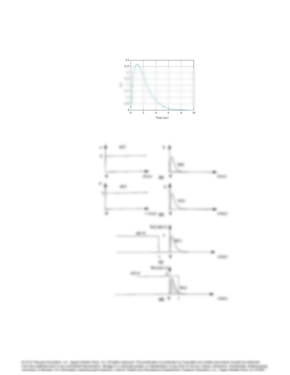
Case (a): For the case t0, the situation is illustrated in the following
3026 CHAPTER 3. DYNAMIC RESPONSE
Figure 3.44: Impulse response for Problem 3.10.
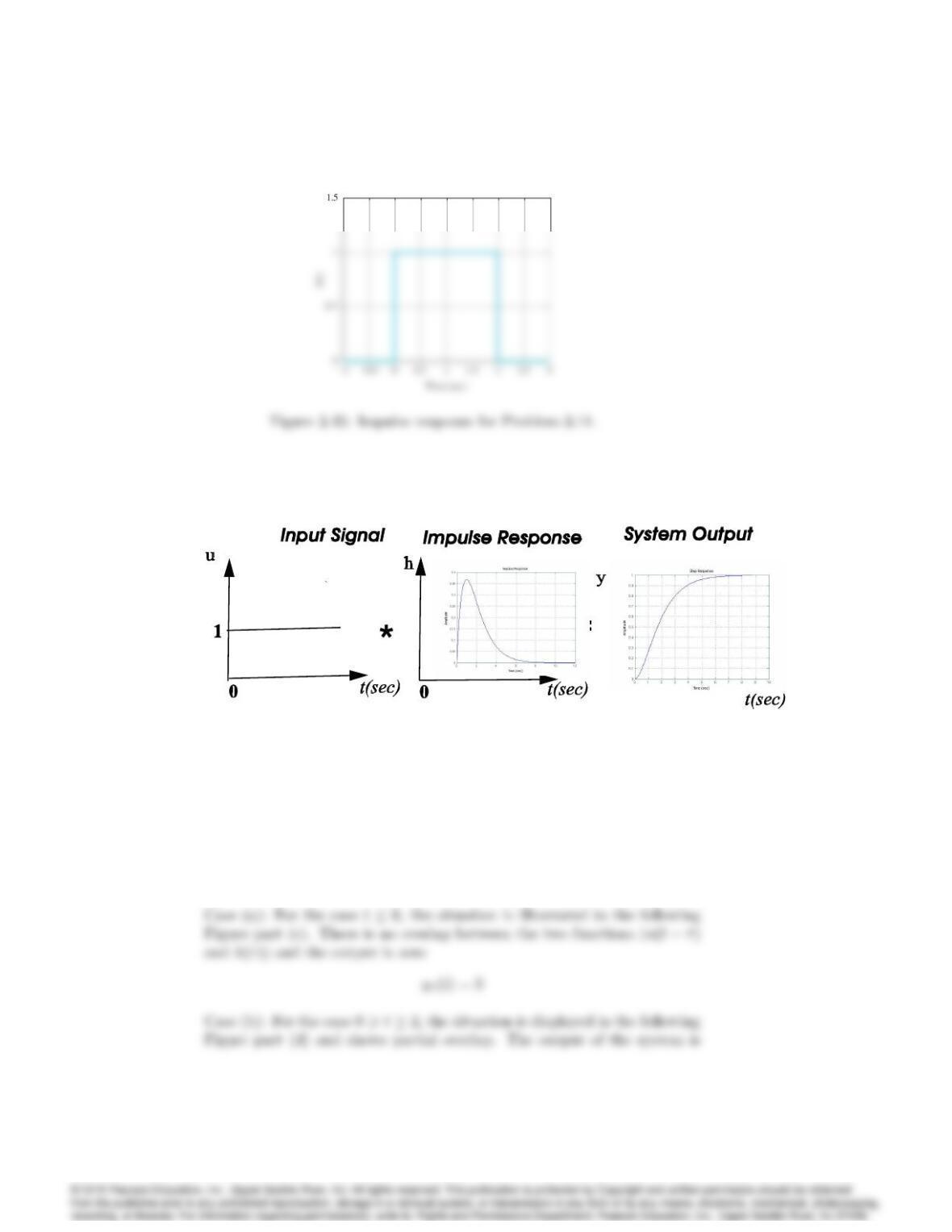
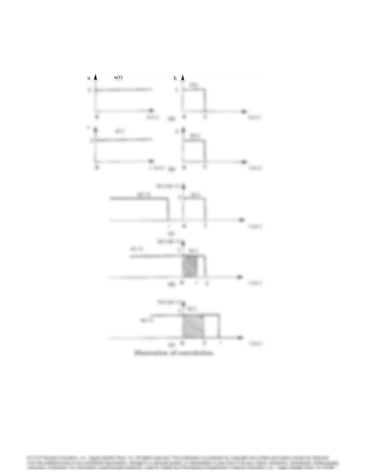
Illustration of convolution.
The output of the system is the composite of the two segments computed
3027
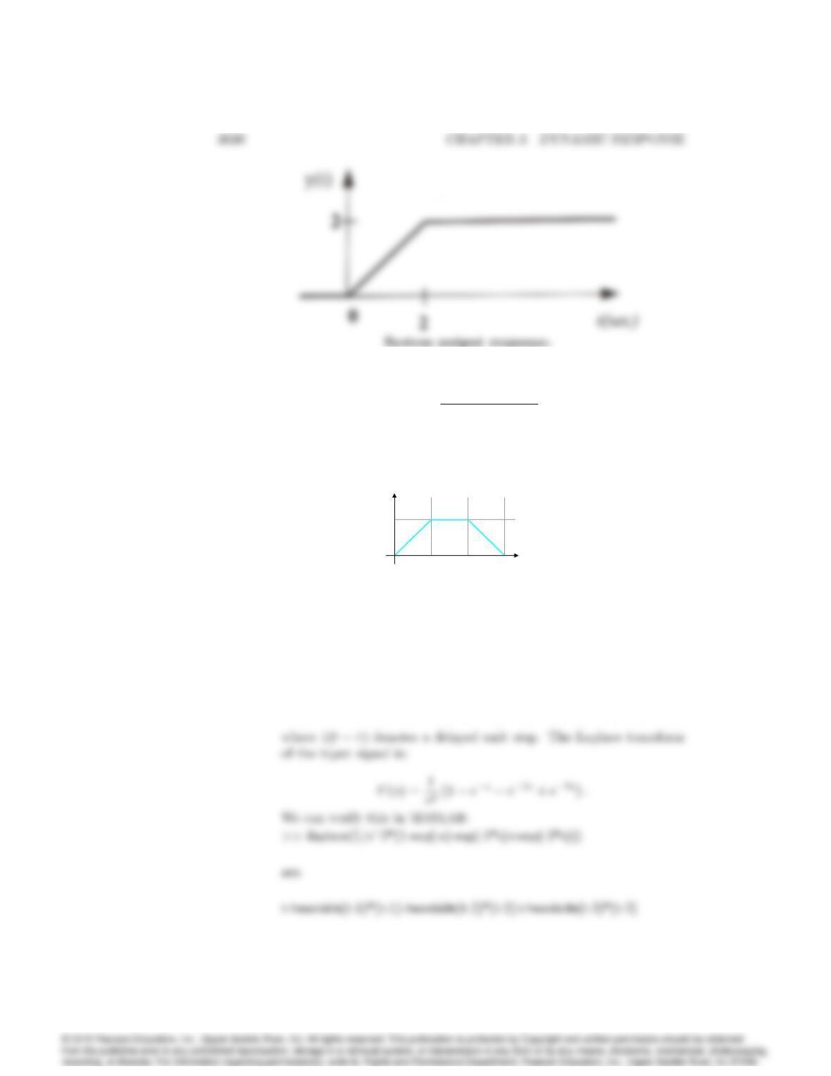
above as shown in the following Figure.
System output response.
11. Using the convolution integral, find the step response of the system whose
impulse response is given below and shown in Figure 3.45:
h(t) = 1 0 t2
0t < 0and t > 2
Solution: There are three cases to consider as shown in the following
figure.
3028 CHAPTER 3. DYNAMIC RESPONSE
given by
3029
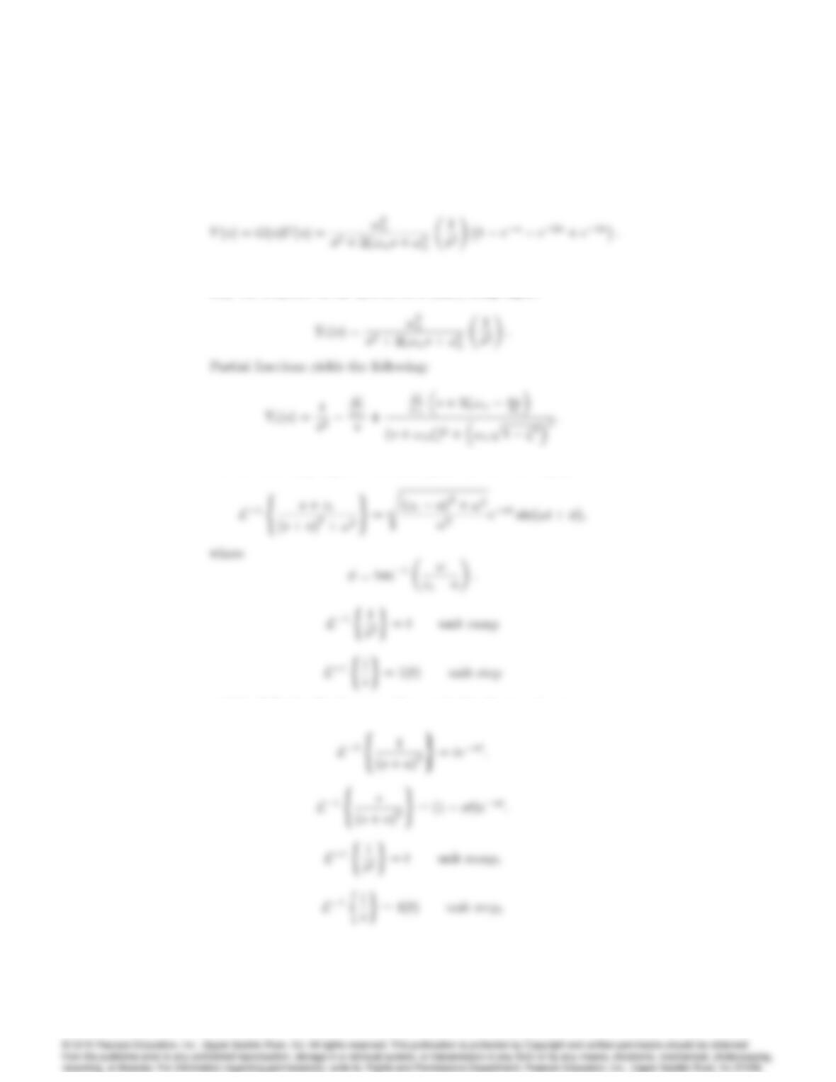
The output of the system is the composite of the three segments computed
above as shown in the following figure.
12. Consider the standard second-order system
G(s) = !2
n
s2+ 2!ns+!2
n
:
a) Write the Laplace transform of the signal in Fig. 3.46. b). What is
the transform of the output if this signal is applied to G(s). c) Find the
output of the system for the input shown in Fig. 3.46.
u(t)
1
1 2 3
T i m e ( s e c )
Figure 3.46: Plot of input for Problem 3.12
Solution:
(a) The input signal may be written as:
u(t) = t(t1) 1(t1) (t2) 1(t2) + (t3) 1(t3);
3031
(b) The Laplace transform of the output if this input signal is applied is:
(c) However to make the mathematical manipulation easier, consider
only the response of the system to a (unit) ramp input:
Use the following Laplace transform pairs for the case 0 < 1:
and the following Laplace transform pairs for the case = 1 :
3032 CHAPTER 3. DYNAMIC RESPONSE
the following is derived:
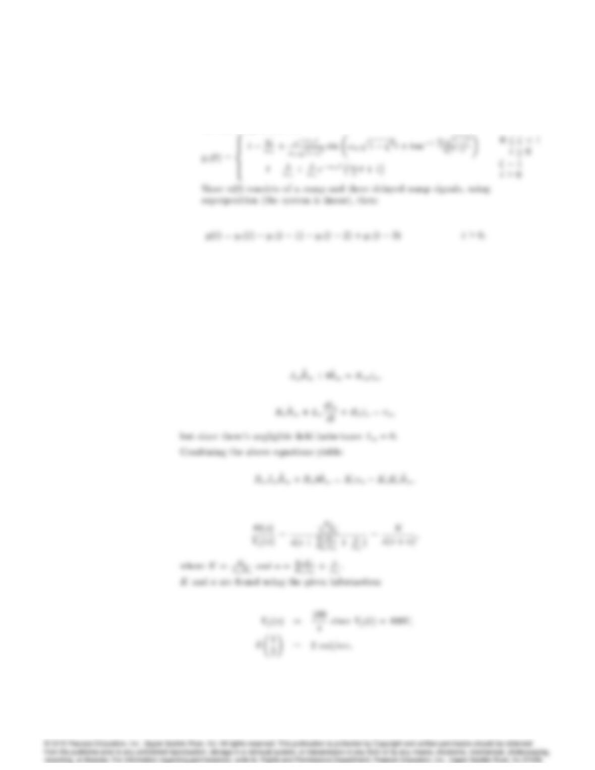
13. A rotating load is connected to a field-controlled DC motor with negligible
field inductance. A test results in the output load reaching a speed of
1 rad/sec within 1/2 sec when a constant input of 100 V is applied to
the motor terminals. The output steady-state speed from the same test is
found to be 2 rad/sec. Determine the transfer function (s)=Vf(s)of the
motor.
Solution:
Equations of motion for a DC motor:
Applying Laplace transforms yields the following transfer function:
3033
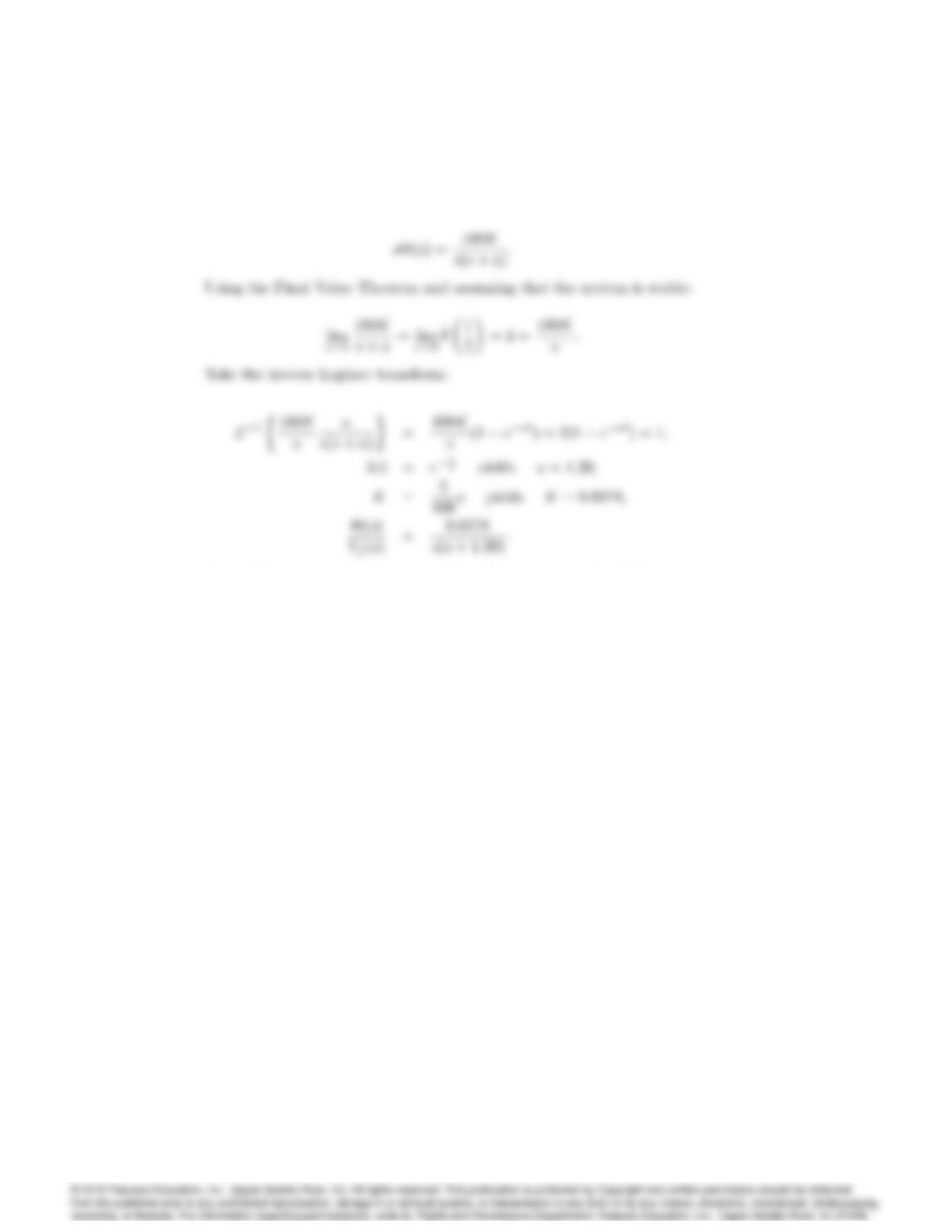
For the given information we need to utilize _
m(t)instead of m(t):
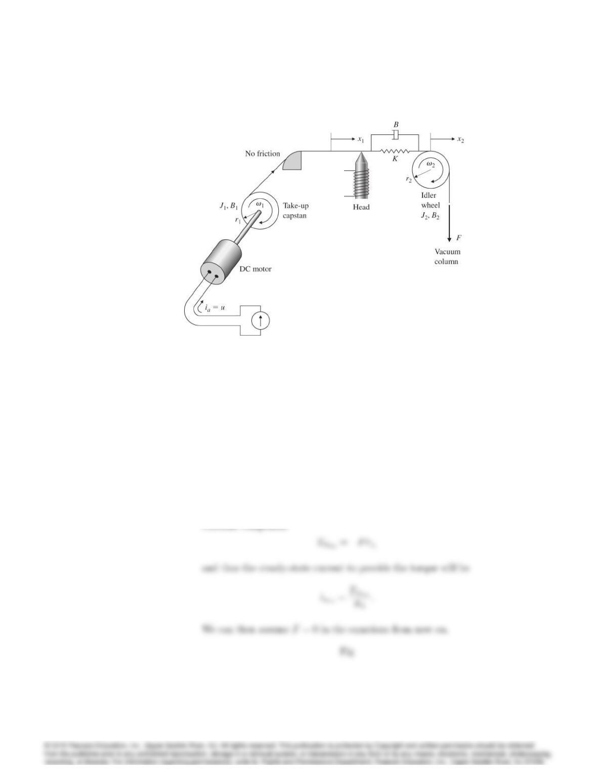
14. A simplified sketch of a computer tape drive is given in Fig. 3.47
(a) Write the equations of motion in terms of the parameters listed below.
Kand Brepresent the spring constant and the damping of tape
stretch, respectively, and !1and !2are angular velocities. A positive
current applied to the DC motor will provide a torque on the capstan
in the clockwise direction as shown by the arrow. Find the value
of current that just cancels the force, F, then eliminate the constant
current and its balancing force, F; from your equations. Assume
positive angular velocities of the two wheels are in the directions
shown by the arrows.
J1= 5 105kg m2;motor and capstan inertia
B1= 1 102Nmsec;motor damping
r1= 2 102m
Kt= 3 102Nm=A;motor torque constant
K= 2 104N=m
B= 20 N=msec
r2= 2 102m
J2= 2 105kg m2
B2= 2 102Nmsec;viscous damping;idler
F= 6 N;constant force
_x1= tape velocity m=sec (variable to be controlled)
3034 CHAPTER 3. DYNAMIC RESPONSE
Figure 3.47: Tape drive schematic
(b) Find the transfer function from the motor current to the tape posi-
tion;
(c) Find the poles and zeros for the transfer function in part (a).
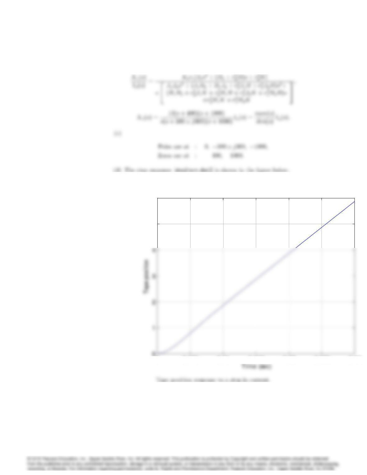
(d) Use MATLAB to find the response of x1to a step input in ia.
Solution:
(a) Because of the force Ffrom the vacuum column, the spring will be
stretched in the steady-state by and the motor torque will have a

3035
Free body diagram for Problem 3.14.
On the capstan side:
We also have:
_x1=r1!1;
_x2=r2!2;
6
4
r10s0
0r20s
7
52
6
4
x1
x2
7
5=2
6
4
0
0
7
5;
3036 CHAPTER 3. DYNAMIC RESPONSE
00.005 0.01 0.015 0.02 0.025 0.03
5
6x 10
-4
00.005 0.01 0.015 0.02 0.025 0.03
5
6x 10
-4
15. For the system in Fig. 2.54, compute the transfer function from the motor
voltage to position 2.
3037
Solution:
From Problem 2.20:
Ldia
dt +Raia+ke_
1=va
So we have:
we have:
16. Compute the transfer function for the two-tank system in Fig. 2.58 with
holes at A and C.
Solution:
From Problem 2.26 but with s=atank area we have:
17. For a second-order system with transfer function
G(s) = 2
s2+s2;
determine the following:
(a) The DC gain;
(b) The final value to a unit step input.
Solution:
(b) lim
t!1y(t) =?
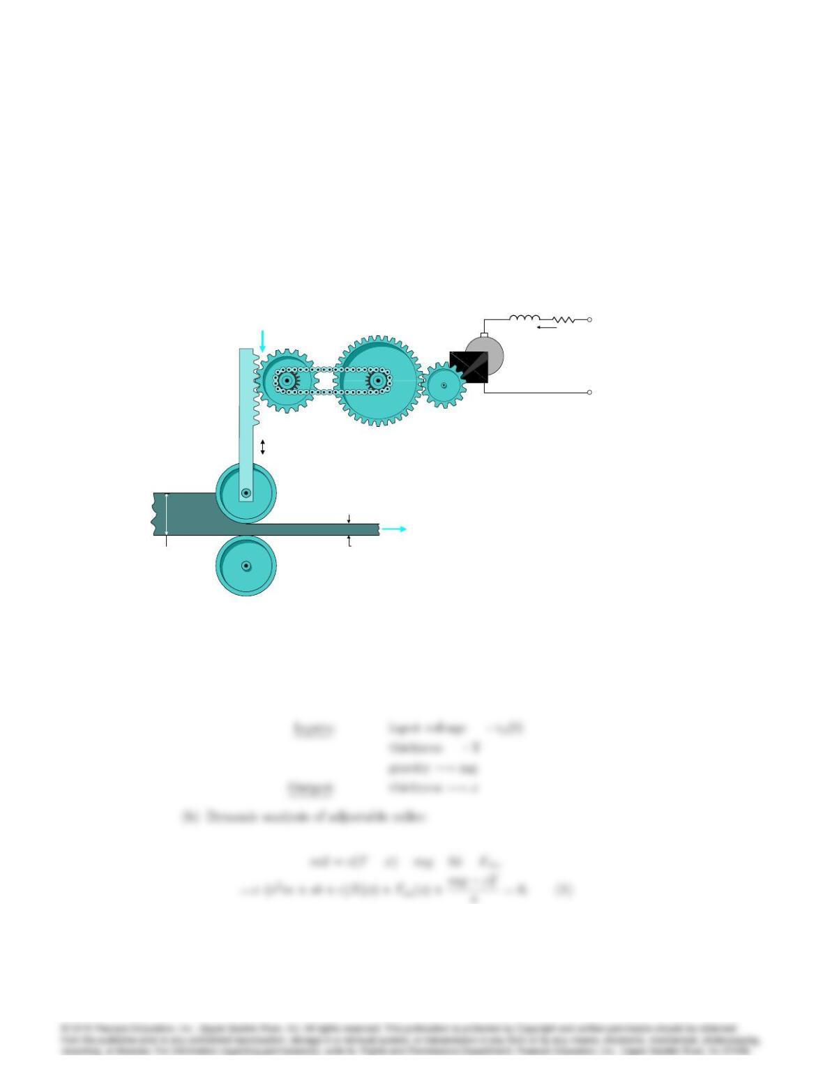
18. Consider the continuous rolling mill depicted in Fig. 3.48. Suppose that
the motion of the adjustable roller has a damping coefficient b, and that the
force exerted by the rolled material on the adjustable roller is proportional
to the material’s change in thickness: Fs=c(Tx). Suppose further that
the DC motor has a torque constant Ktand a back-emf constant Ke, and
that the rack-and-pinion has effective radius of R.
3039
(a) What are the inputs to this system? The output?
(b) Without neglecting the effects of gravity on the adjustable roller,
draw a block diagram of the system that explicitly shows the follow-
ing quantities: Vs(s),I0(s); F (s)(the force the motor exerts on the
adjustable roller), and X(s).
(c) Simplify your block diagram as much as possible while still identifying
output and each input separately.
1
2
io(t)
2
1
va(t)vs(t
1 : N
G e a r r a t i o
R a c k a n d
P i n i o n
M o tio n o f
m a t e r i a l
o u t o f r o l l e r s
T h i c k n e s s TT h i c k n e s s x
V e r t i c a l l y
a d j u s t a b l e
r o l l e r
F i x e d
r o l l e r
LaRa
Fm
Figure 3.48: Continuous rolling mill
Solution:
(a)