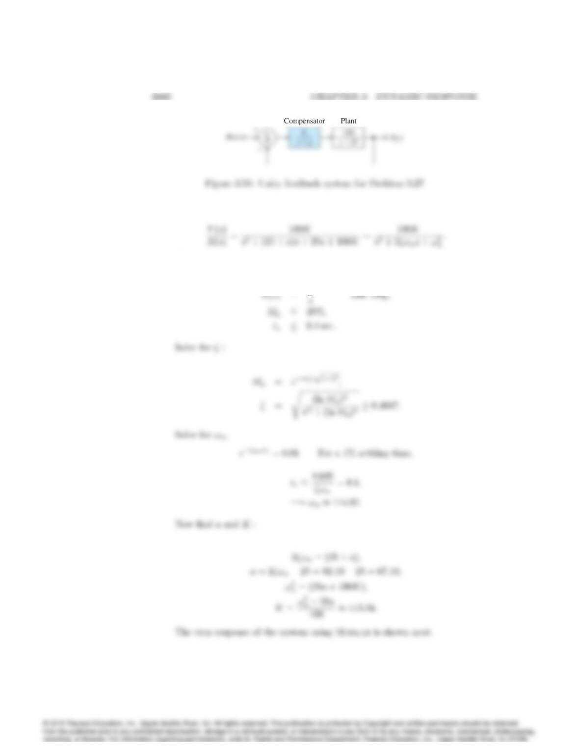
Using the given information:
00.05 0.1 0.15 0.2
0.4
0.8
1.4
Time (sec)
y(t)
00.05 0.1 0.15 0.2
0.4
0.8
1.4
Time (sec)
y(t)
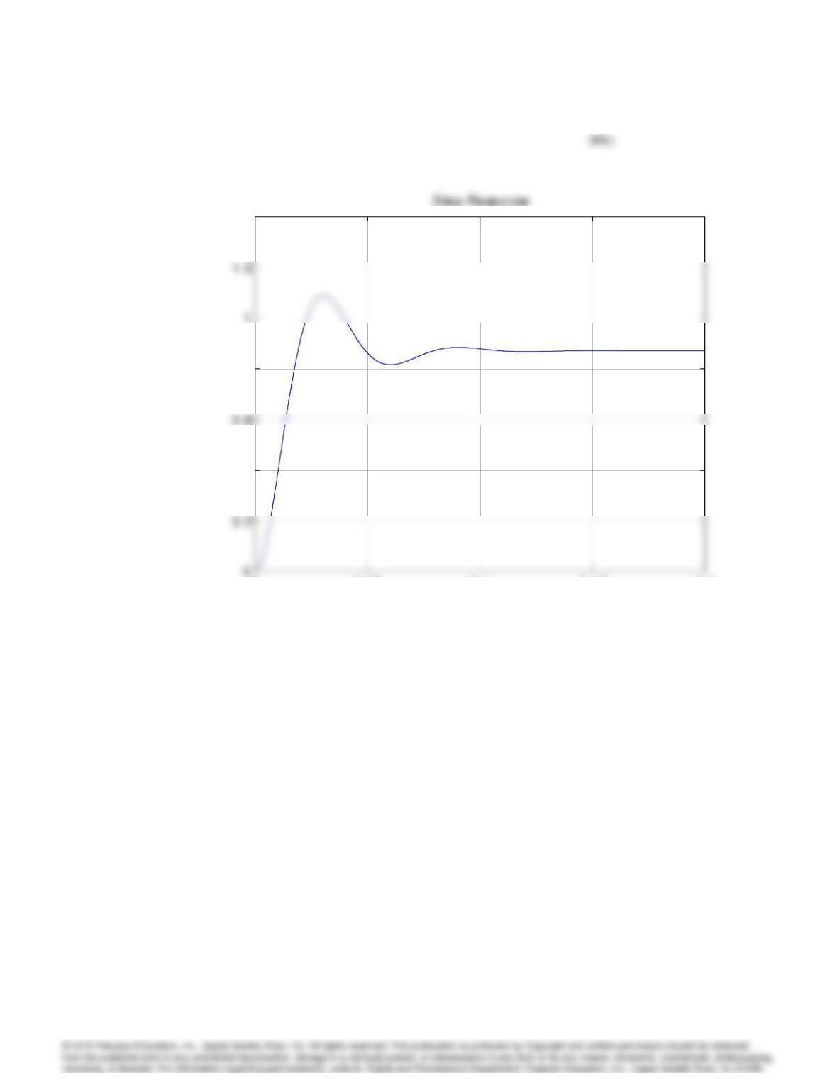
Step response for Problem 3.27.
Problems and Solutions for Section 3.4: Time–
Domain Specifications
28. Suppose you desire the peak time of a given second-order system to be
less than t0
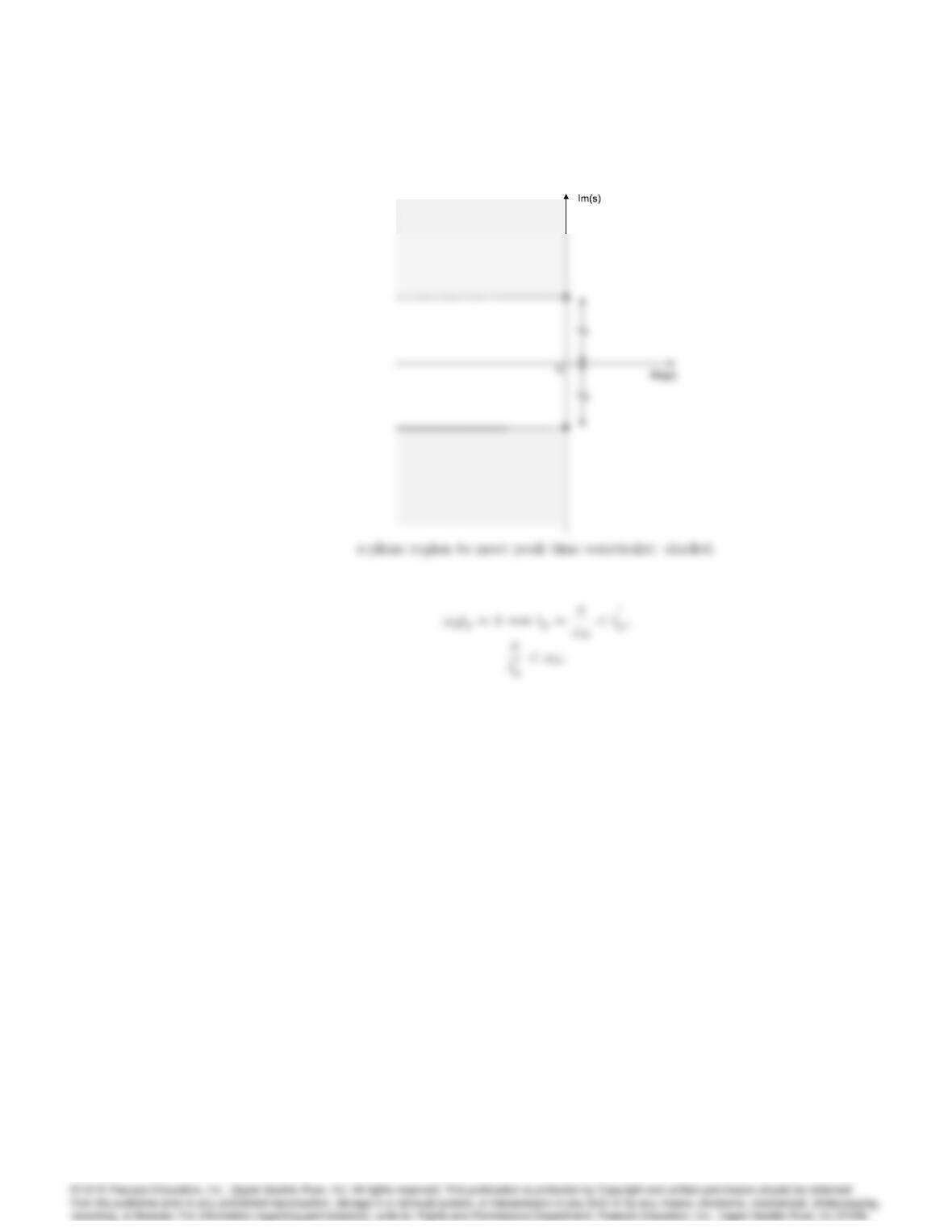
p. Draw the region in the s-plane that corresponds to values of
the poles that meet the specification tp< t0
p.
Solution:
3062 CHAPTER 3. DYNAMIC RESPONSE
29. A certain servomechanism system has dynamics dominated by a pair of
complex poles and no finite zeros. The time-domain specifications on the
rise time (tr), percent overshoot
(Mp), and settling time (ts) are given by,
tr0:6 sec ,
Mp17%,
ts9:2 sec .
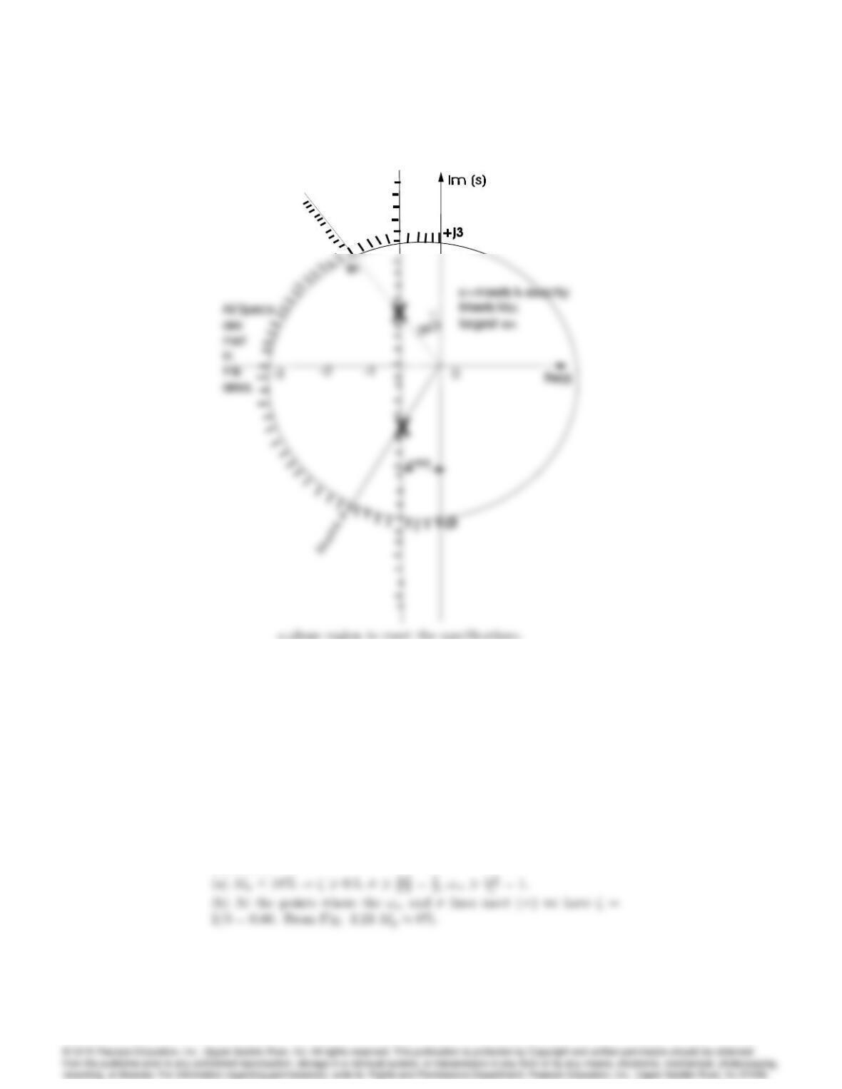
(a) Sketch the region in the s-plane where the poles could be placed
so that the system will meet all three specifications.
(b) Indicate on your sketch the specific locations (denoted by ) that
will have the smallest rise-time and also meet the settling time specification
exactly.
Solution:
(a)-(b)
3063
s-plane region to meet the specifications.
30. A feedback system has the following response specifications,
Percent overshoot Mp16%.
Settling time ts6:9sec.
Rise time tr1:8sec.
(a) Sketch the region of acceptable closed-loop poles in the s-plane for
the system assuming the transfer function can be approximated as
simple second-order.
(b) What is the expected overshoot if the rise time and settling time
specifications are met exactly?
Solution:
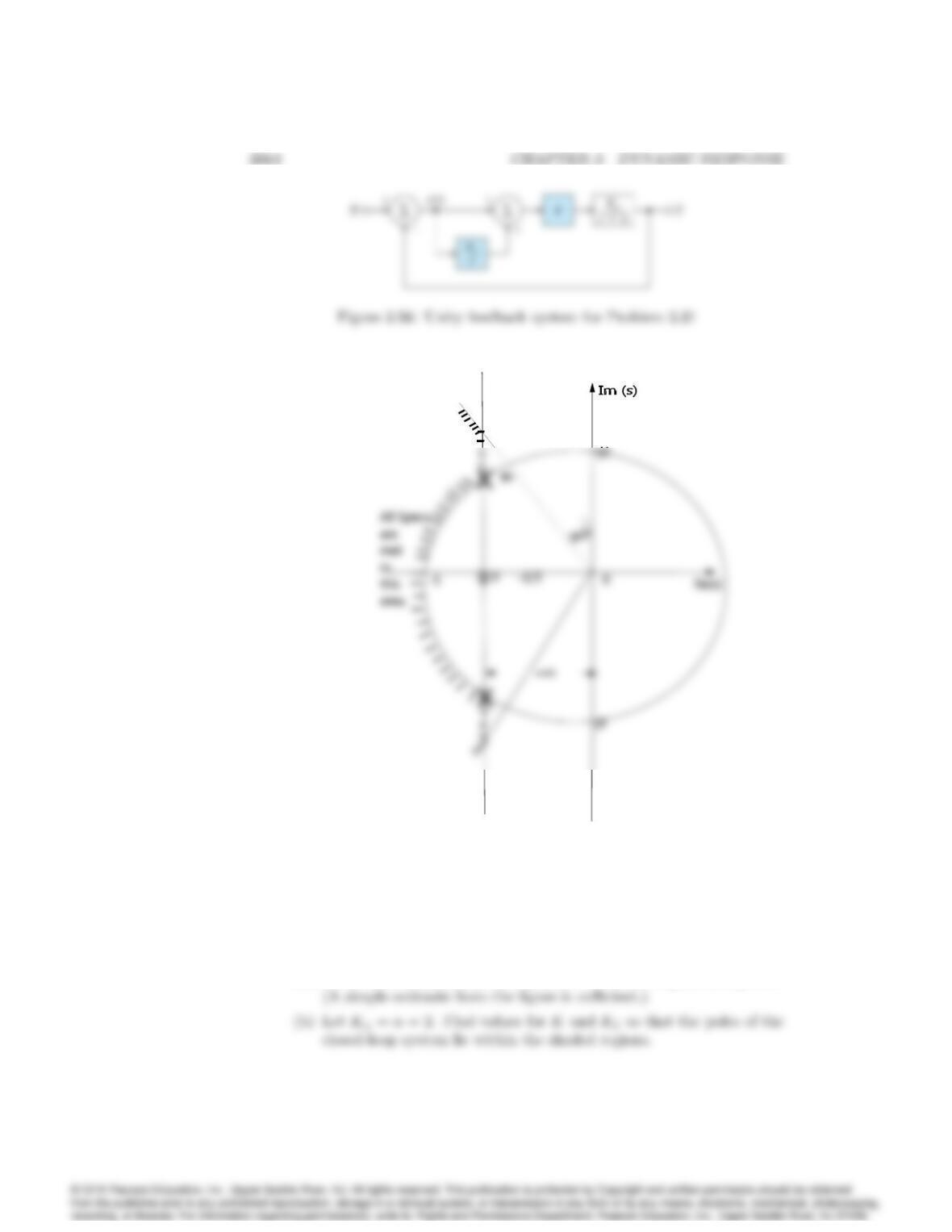
s-plane region to meet the specifications.
31. Suppose you are to design a unity feedback controller for a first-order plant
depicted in Fig. 3.56. (As you will learn in Chapter 4, the configuration
shown is referred to as a proportional-integral controller.) You are to
design the controller so that the closed-loop poles lie within the shaded
regions shown in Fig. 3.57.
(a) What values of !nand correspond to the shaded regions in Fig. 3.57?
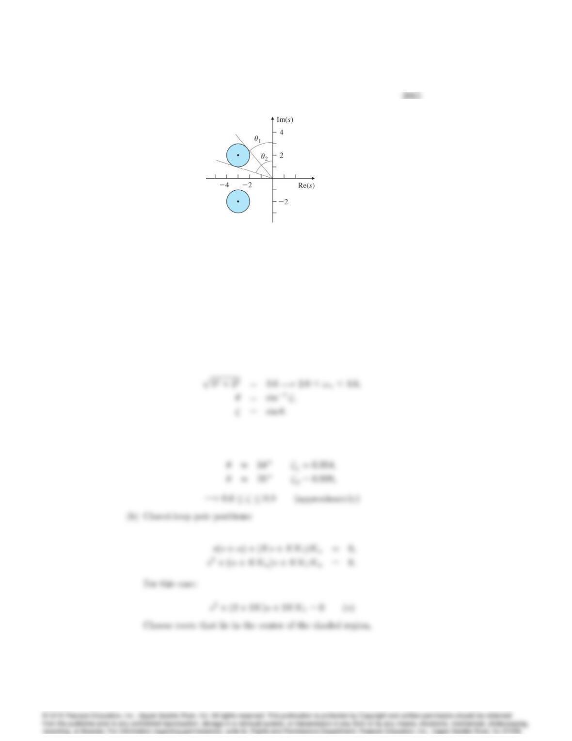
Figure 3.57: Desired closed-loop pole locations for Problem 3.31
(c) Prove that no matter what the values of Kand are, the controller
provides enough ‡exibility to place the poles anywhere in the complex
(left-half) plane.
Solution:
(a) The values could be worked out mathematically but working from
the diagram:
From the figure:
3066 CHAPTER 3. DYNAMIC RESPONSE
32. The open-loop transfer function of a unity feedback system is
G(s) = K
s(s+ 2):
The desired system response to a step input is specified as peak time
tp= 1 sec and overshoot Mp= 5%.
(a) Determine whether both specifications can be met simultaneously by
selecting the right value of K.
(b) Sketch the associated region in the s-plane where both specifications
are met, and indicate what root locations are possible for some likely
values of K.
(c) Pick a suitable value for K, and use Matlab to verify that the spec-
ifications are satisfied.
Solution:
(a)
3067
(b) Now we wish to have:
replace !nand in the system (**):
then with K= 3:02 we will have:
3068 CHAPTER 3. DYNAMIC RESPONSE
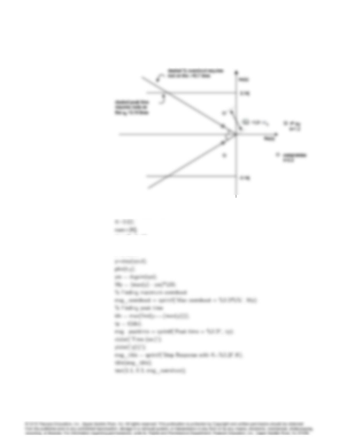
s-plane regions.
% Problem 3.32 FPE7e
den=[1, 2, K];
sys=tf(num,den);
t=0:.01:7;
grid on;
0.2
0.4
0.8
1.4
y(t)
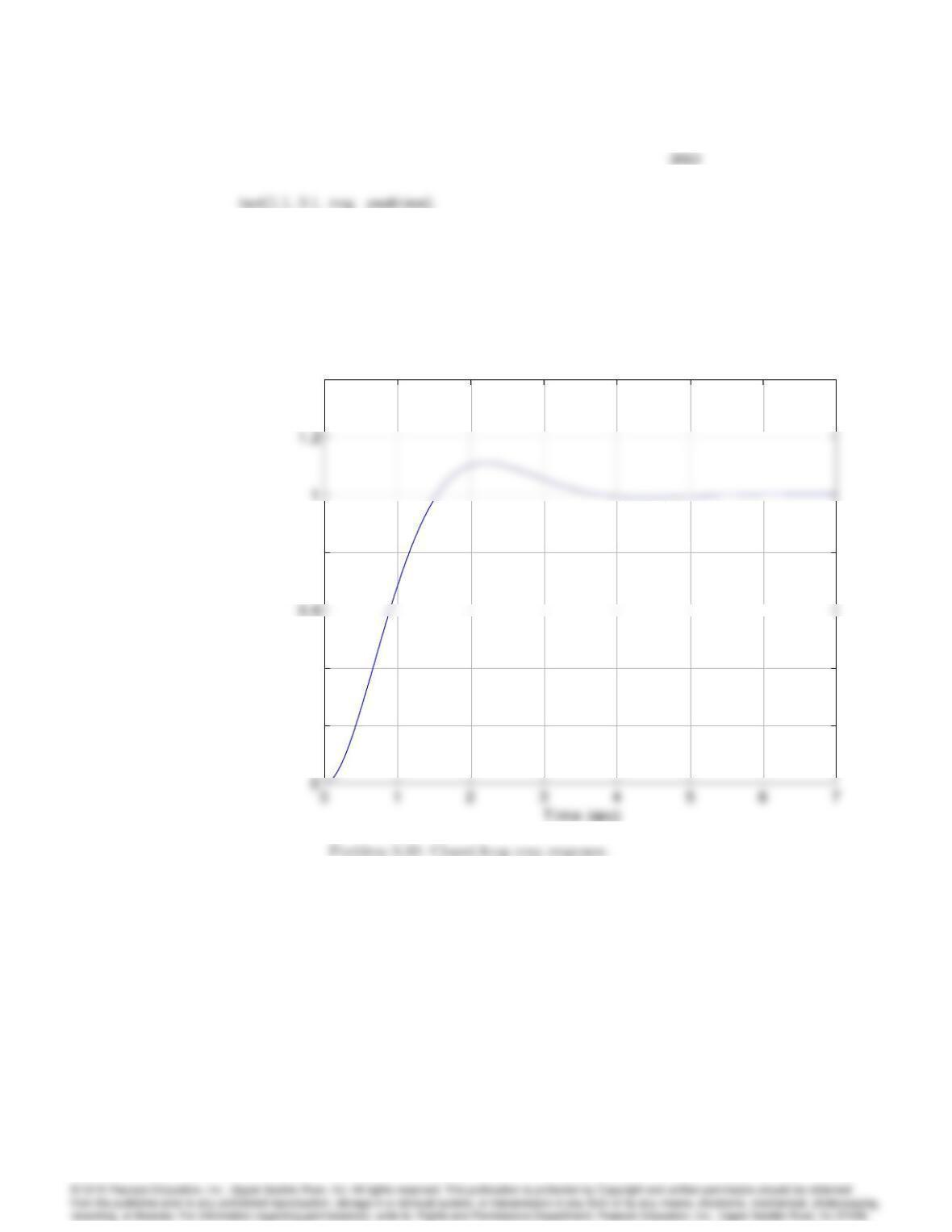
Step Response with K=3.02
Max overshoot = 10.97%
Peak time = 2.21
0.2
0.4
0.8
1.4
y(t)
Step Response with K=3.02
Max overshoot = 10.97%
Peak time = 2.21
33. A simple mechanical system is shown in Fig. 3.58 (a). The parameters are
k=spring constant, b=viscous friction constant, m=mass. A step of 2
Newtons force is applied as f= 2 1(t)and the resulting step response
is shown in Fig. 3.58 (b). What are the values of the system parameters
k,b, and m?
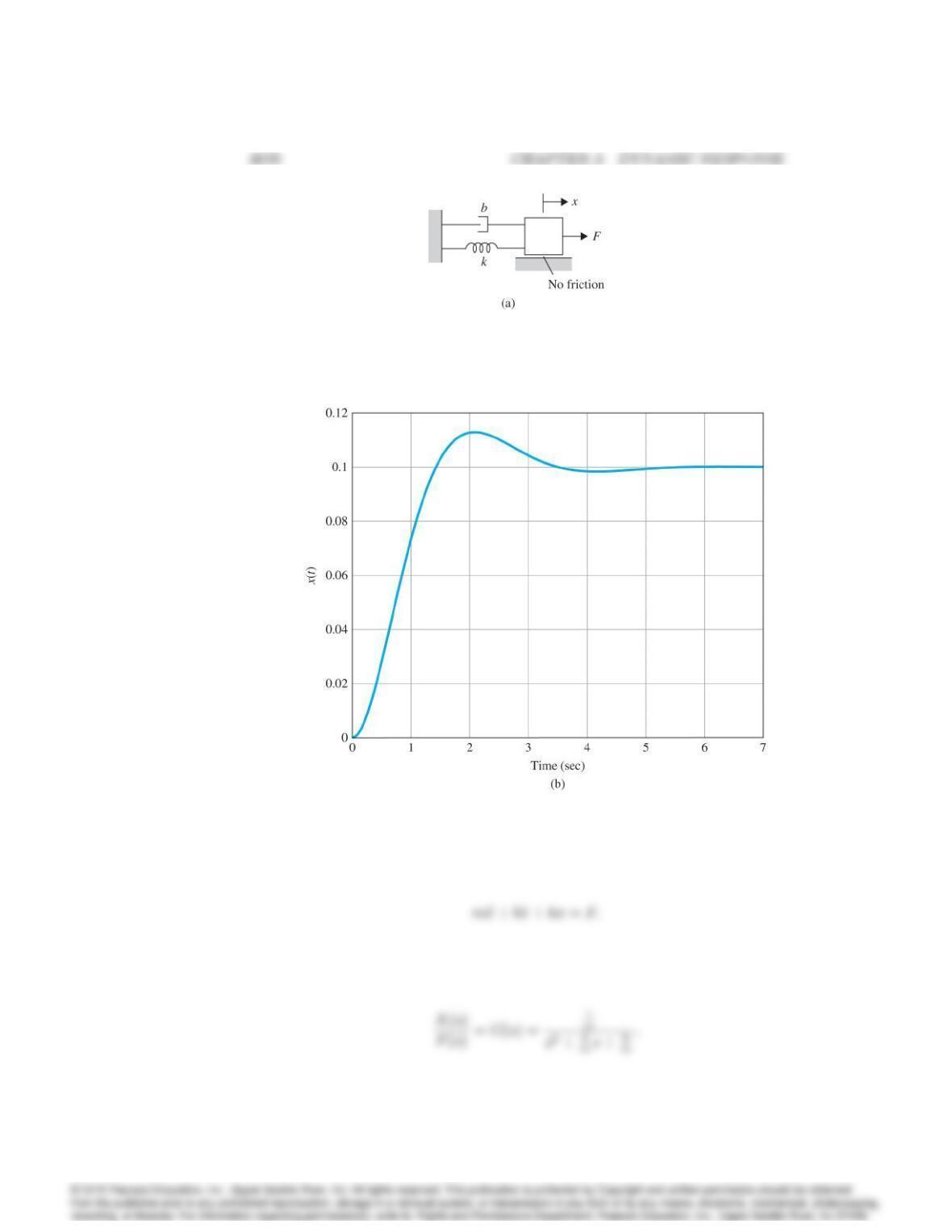
Figure 3.58: (a) Mechanical system for Problem 3.33
(b) Step response for Problem 3.33
Solution: The equation of motion is
The transfer function is
In this case
From the plot
34. A mechanical system is shown in Fig. 3.59. The mass M= 20 kg and the
control force, u, is proportional to the reference input, u=Ar.
(a) Derive the transfer function from Rto Y.
(b) Determine the values of the parameters k,b,Asuch that the system
has a rise time of tr= 1 sec and overshoot of Mp= 16%, and zero-steady-
state error to a step in r.
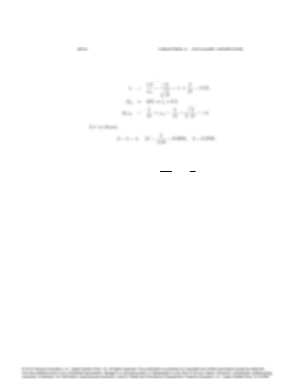
Solution: (a) The equation of motion is
(b)
T(0) = 1 )A
k= 1;
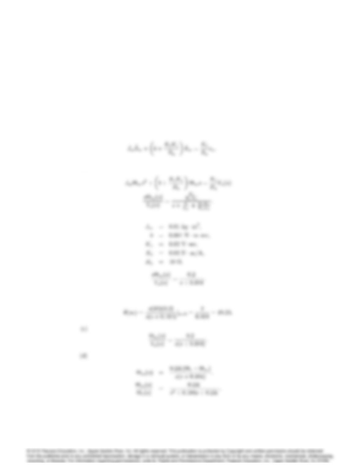
35. The equations of motion for the DC motor shown in Fig. 2.32 were given
in Eqs. (2.62-63) as
Jm•
m+b+KtKe
Ra_
m=Kt
Ra
va:
Assume that
Jm= 0:01 kg m2;
b= 0:001 N msec;
Ke= 0:02 V sec;
Kt= 0:02 N m=A;
Ra= 10 :
(a) Find the transfer function between the applied voltage vaand the
motor speed _
m.
(b) What is the steady-state speed of the motor after a voltage va= 10 V
has been applied?
(c) Find the transfer function between the applied voltage vaand the
shaft angle m.
(d) Suppose feedback is added to the system in part (c) so that it becomes
a position servo device such that the applied voltage is given by
va=K(rm);
where Kis the feedback gain. Find the transfer function between r
and m.
(e) What is the maximum value of Kthat can be used if an overshoot
Mp<20% is desired?
3073
(f) What values of Kwill provide a rise time of less than 4 sec? (Ignore
the Mpconstraint.)
(g) Use Matlab to plot the step response of the position servo system
for values of the gain K= 0:5, 1, and 2. Find the overshoot and rise
time for each of the three step responses by examining your plots.
Are the plots consistent with your calculations in parts (e) and (f)?
Solution:
(a)
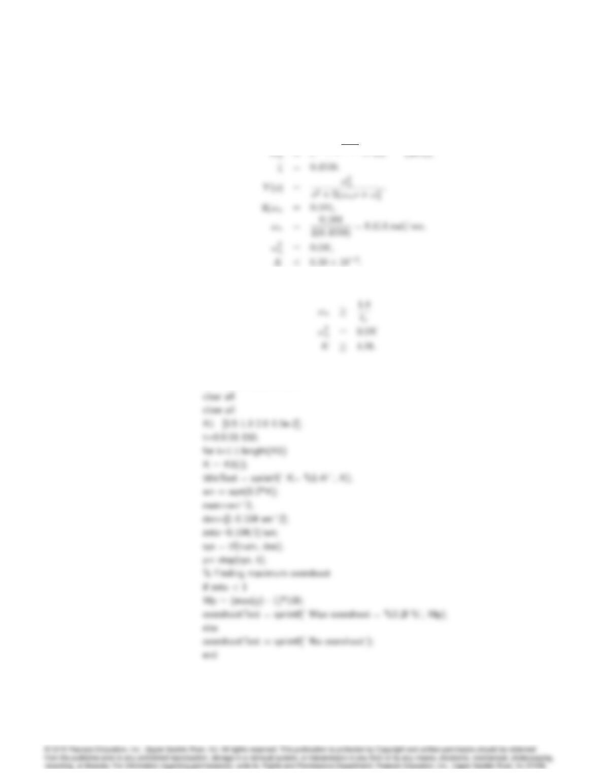
(b) Final Value Theorem
3074 CHAPTER 3. DYNAMIC RESPONSE
(e)
(f)
(g) Matlab
% Problem 3.35 FPE7e
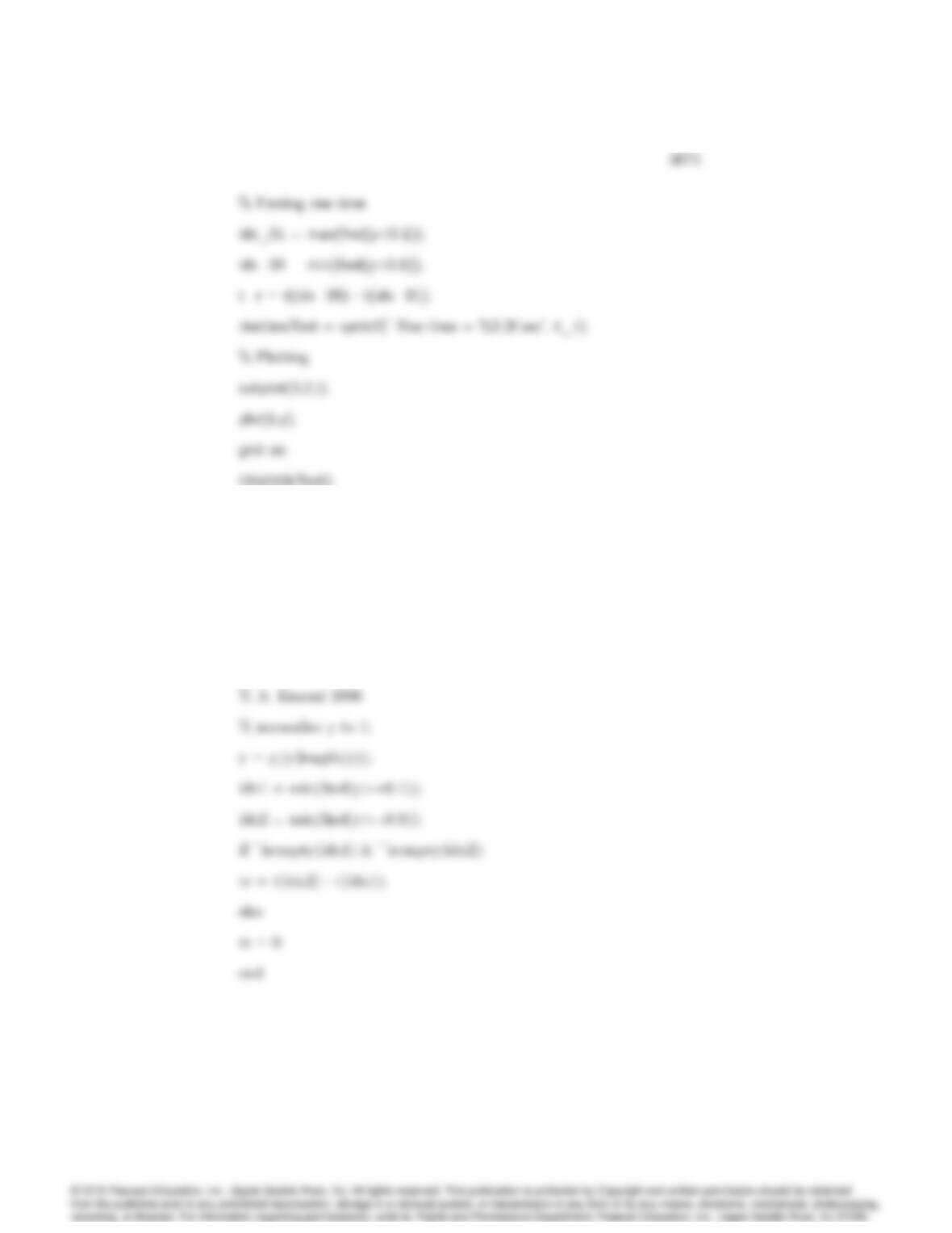
text( 0.5, 0.3, overshootText);
text( 0.5, 0.1, risetimeText);
end
%%%%%%%%%%%%%%%%
% Function for computing rise time
function tr = risetime(t,y)
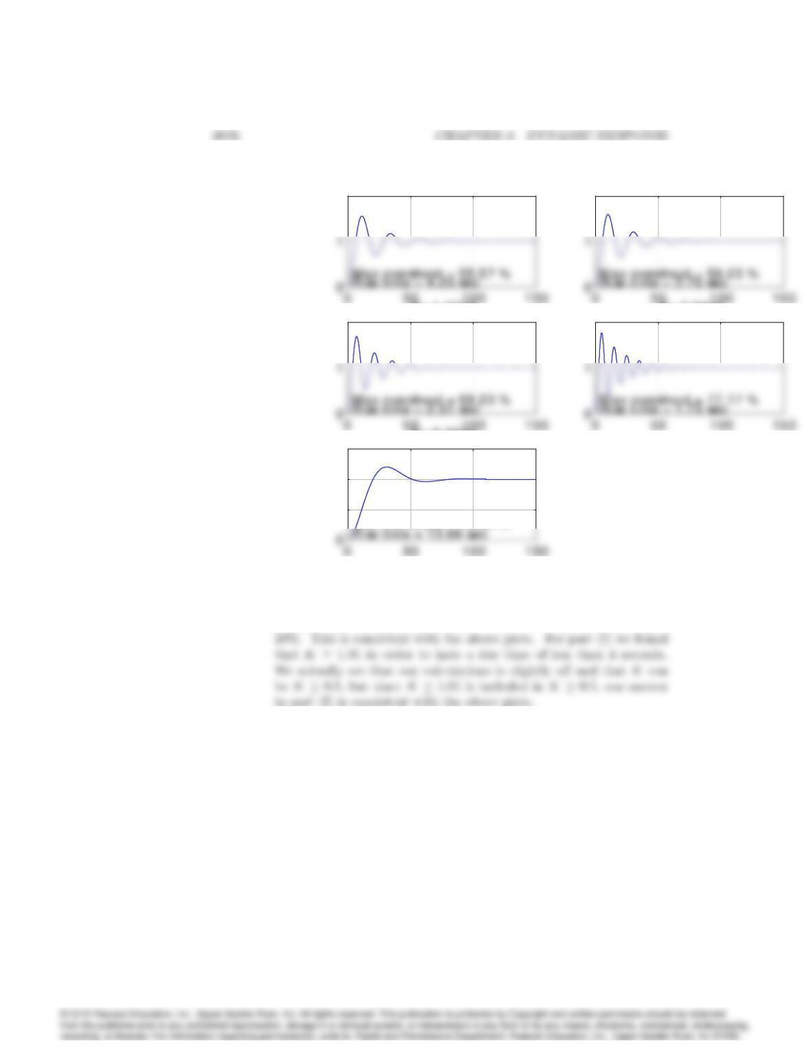
2
K= 0.4000
2
K= 0.5000
2
K= 1.0000
2
K= 2.0000
0.5
1
1.5
K= 0.0650
Max overshoot = 19.99 %
2
K= 0.4000
2
K= 0.5000
2
K= 1.0000
2
K= 2.0000
0.5
1
1.5
K= 0.0650
Max overshoot = 19.99 %
Problem 3.35: Closed-loop step responses for several values of K.
For part (e) we concluded that K < 6:50 102in order for Mp<
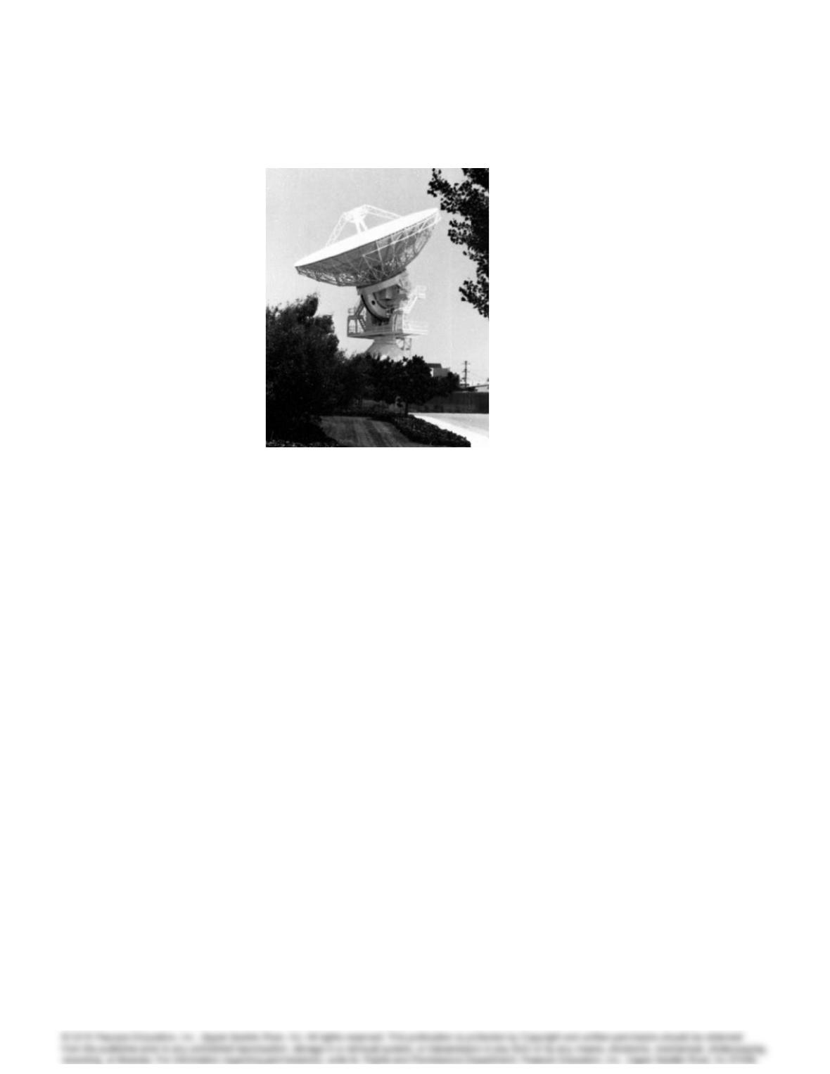
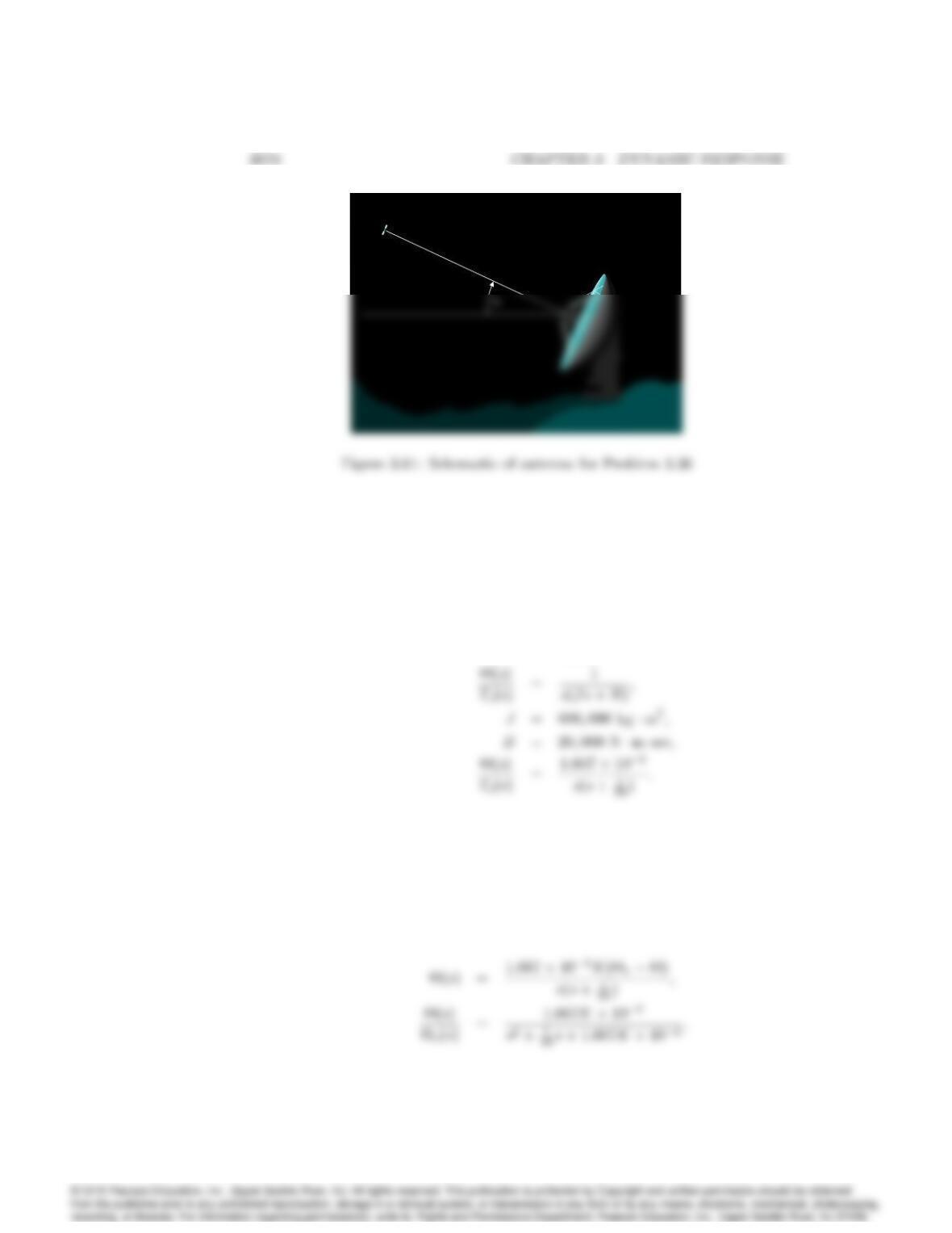
36. You wish to control the elevation of the satellite-tracking antenna shown
in Figs. 3.60 and 3.61. The antenna and drive parts have a moment of
inertia Jand a damping B; these arise to some extent from bearing and
aerodynamic friction, but mostly from the back emf of the DC drive motor.
The equations of motion are
J•
+B_
=Tc;
where Tcis the torque from the drive motor. Assume that
J= 600;000 kgm2B= 20;000 Nmsec:
3077
Figure 3.60: Satellite Antenna (Courtesy Space Systems/Loral)
(a) Find the transfer function between the applied torque Tcand the
antenna angle .
(b) Suppose the applied torque is computed so that tracks a reference
command raccording to the feedback law
Tc=K(r);
where Kis the feedback gain. Find the transfer function between r
and .
(c) What is the maximum value of Kthat can be used if you wish to
have an overshoot Mp<10%?
(d) What values of Kwill provide a rise time of less than 80 sec? (Ignore
the Mpconstraint.)
(e) Use Matlab to plot the step response of the antenna system for
K= 200, 400, 1000, and 2000. Find the overshoot and rise time
of the four step responses by examining your plots. Do the plots to
confirm your calculations in parts (c) and (d)?
Solution:
J•
+B_
=Tc
(a)
Js2+Bs=Tc(s);
(b)
3079
(c)
(d)