2036 CHAPTER 2. DYNAMIC MODELS
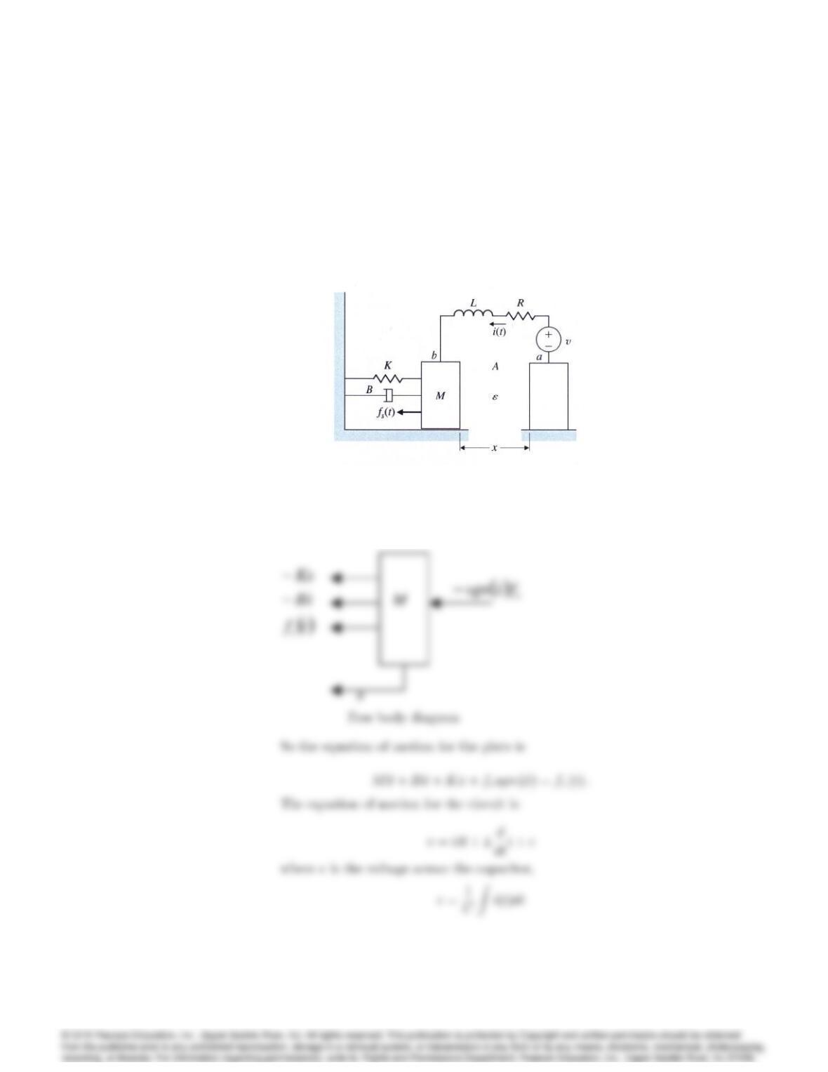
(a) Write differential equations that describe the operation of this sys-
tem. (It is acceptable to leave in nonlinear form.)
(b) Can one get a linear model?
(c) What is the output of the system?
Figure 2.53: Simplified model for capacitor microphone
Solution:
(a) The free body diagram of the capacitor plate b
2037
20. A very typical problem of electromechanical position control is an electric
motor driving a load that has one dominant vibration mode. The problem
arises in computer-disk-head control, reel-to-reel tape drives, and many
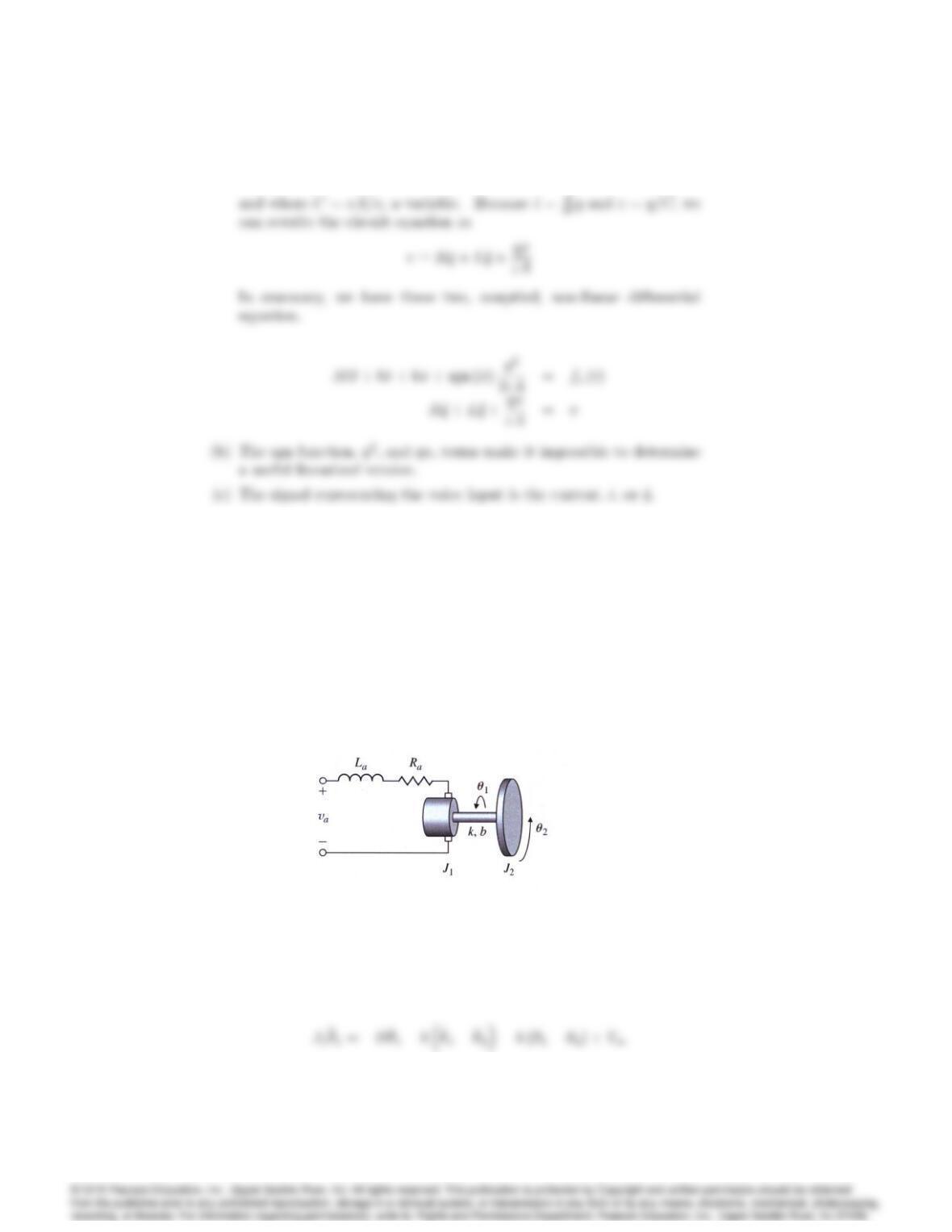
other applications. A schematic diagram is sketched in Fig. 2.54. The
motor has an electrical constant Ke, a torque constant Kt, an armature
inductance La, and a resistance Ra. The rotor has an inertia J1and
a viscous friction B. The load has an inertia J2. The two inertias are
connected by a shaft with a spring constant kand an equivalent viscous
damping b. Write the equations of motion.
Figure 2.54: Motor with a ‡exible load
(a)
Solution:
(a) Rotor:
2038 CHAPTER 2. DYNAMIC MODELS
Load:
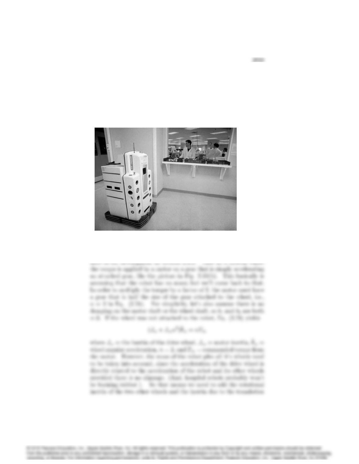
21. For the robot in Fig. 2.45, assume you have command of the torque on a
servo motor that is connected to the drive wheels with gears that have a
2:1 ratio so that the torque on the wheels is increased by a factor of 2 over
that delivered by the servo. Determine the dynamic equations relating
the speed of the robot with respect to the torque command of the servo.
Your equations will require certain quantities, e.g., mass of vehicle, inertia
and radisus of the wheels, etc. Assume you have access to whatever you
need. .
Fig. 2.45 Hospital robot
(a) Solution: First, let’s consider the problem for the case along the
2040 CHAPTER 2. DYNAMIC MODELS
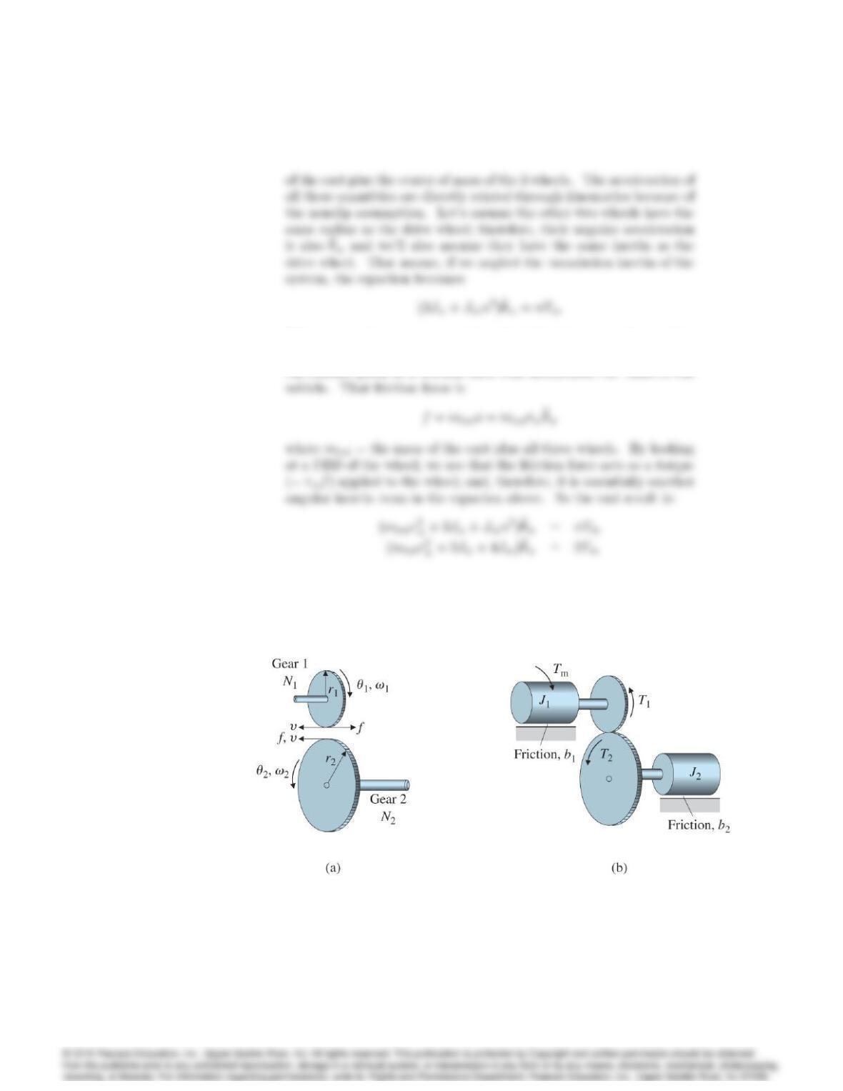
When you apply a torque to a drive wheel, that torque partly provides
an angular accelation of the wheel and the remainder is tranferred to
the contact point as a friction force that accelerates the mass of the
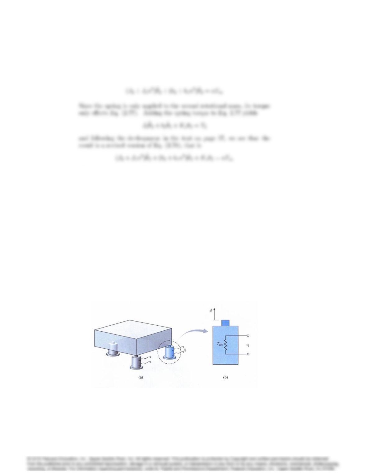
22. Using Fig. 2.35, derive the transfer function between the applied torque,
Tm, and the output, 2;for the case when there is a spring attached to
the output load. That is, there is a torque applied to the output load,
Ts;where Ts=Ks2
Fig. 2.35 (a) geometry definitions and forces on teeth (b) definitions for the
dynamic analysis.
2041
Solution: Equation (2.78), repeated, is
Problems and Solutions for Section 2.4
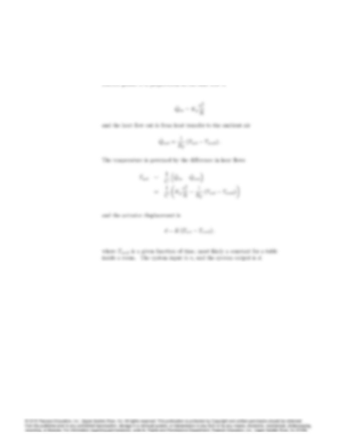
23. A precision-table leveling scheme shown in Fig. 2.57 relies on thermal
expansion of actuators under two corners to level the table by raising or
lowering their respective corners. The parameters are:
Tact = actuator temperature;
Tamb = ambient air temperature;
Rf= heat ow coefficient between the actuator and the air;
C= thermal capacity of the actuator;
R= resistance of the heater:
Assume that (1) the actuator acts as a pure electric resistance, (2) the
heat ‡ow into the actuator is proportional to the electric power input,
and (3) the motion dis proportional to the difference between Tact and
Tamb due to thermal expansion. Find the differential equations relating
the height of the actuator dversus the applied voltage vi.
Fig. 2.57 (a) Precision table kept level by actuators; (b) side view of one
actuator
2042 CHAPTER 2. DYNAMIC MODELS
Solution:
24. An air conditioner supplies cold air at the same temperature to each room
on the fourth ‡oor of the high-rise building shown in Fig. 2.58(a). The ‡oor
plan is shown in Fig. 2.58(b). The cold air ‡ow produces an equal amount
of heat ‡ow qout of each room. Write a set of differential equations
governing the temperature in each room, where
To= temperature outside the building;
Ro= resistance to heat ow through the outer walls;
Ri= resistance to heat ow through the inner walls:
Assume that (1) all rooms are perfect squares, (2) there is no heat ‡ow
through the ‡oors or ceilings, and (3) the temperature in each room is
uniform throughout the room. Take advantage of symmetry to reduce the
number of differential equations to three.
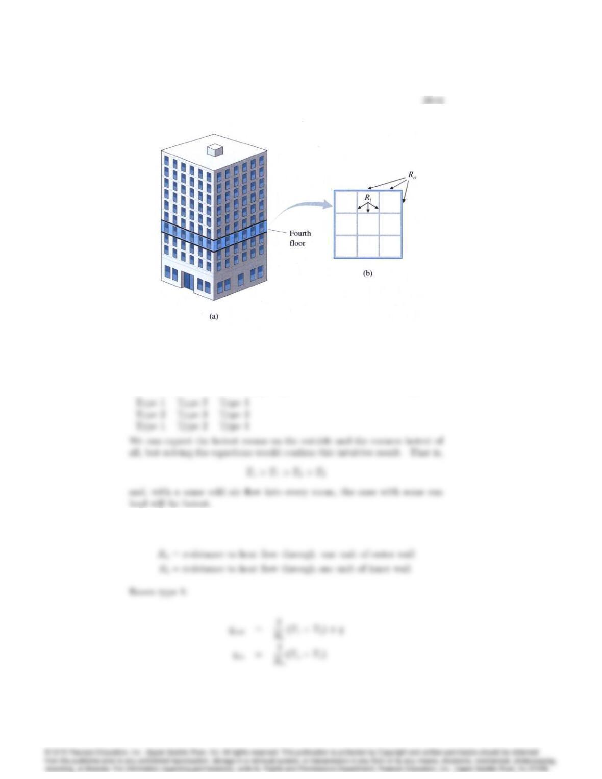
Fig. 2.58 Building air conditioning: (a) high-rise building, (b) ‡oor plan
of the fourth ‡oor
Solution:
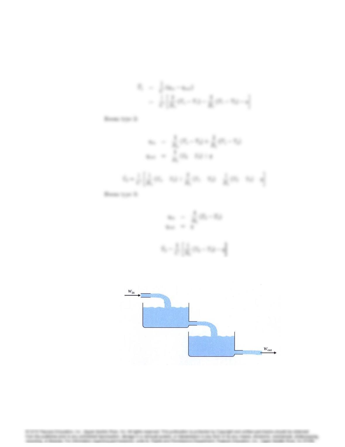
We can classify 9 rooms to 3 types by the number of outer walls they have.
Let’s redefince the resistances
2044 CHAPTER 2. DYNAMIC MODELS
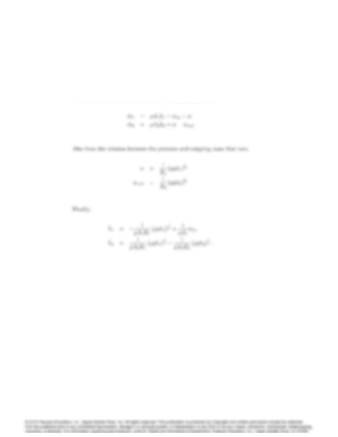
25. For the two-tank ‡uid-‡ow system shown in Fig. 2.59, find the differential
equations relating the ‡ow into the first tank to the ‡ow out of the second
tank.
Fig. 2.59 Two-tank ‡uid-‡ow system for Problem 25
2045
Solution:
This is a variation on the problem solved in Example 2.19 and the defini-
tions of terms is taken from that. From the relation between the height
of the water and mass ‡ow rate, the continuity equations are
26. A laboratory experiment in the ‡ow of water through two tanks is sketched
in Fig. 2.60. Assume that Eq. (2.93) describes ‡ow through the equal-sized
holes at points A, B, or C.
(a) With holes at B and C but none at A, write the equations of motion
for this system in terms of h1and h2. Assume that when h2= 10 cm,
the out‡ow is 200 g/min.
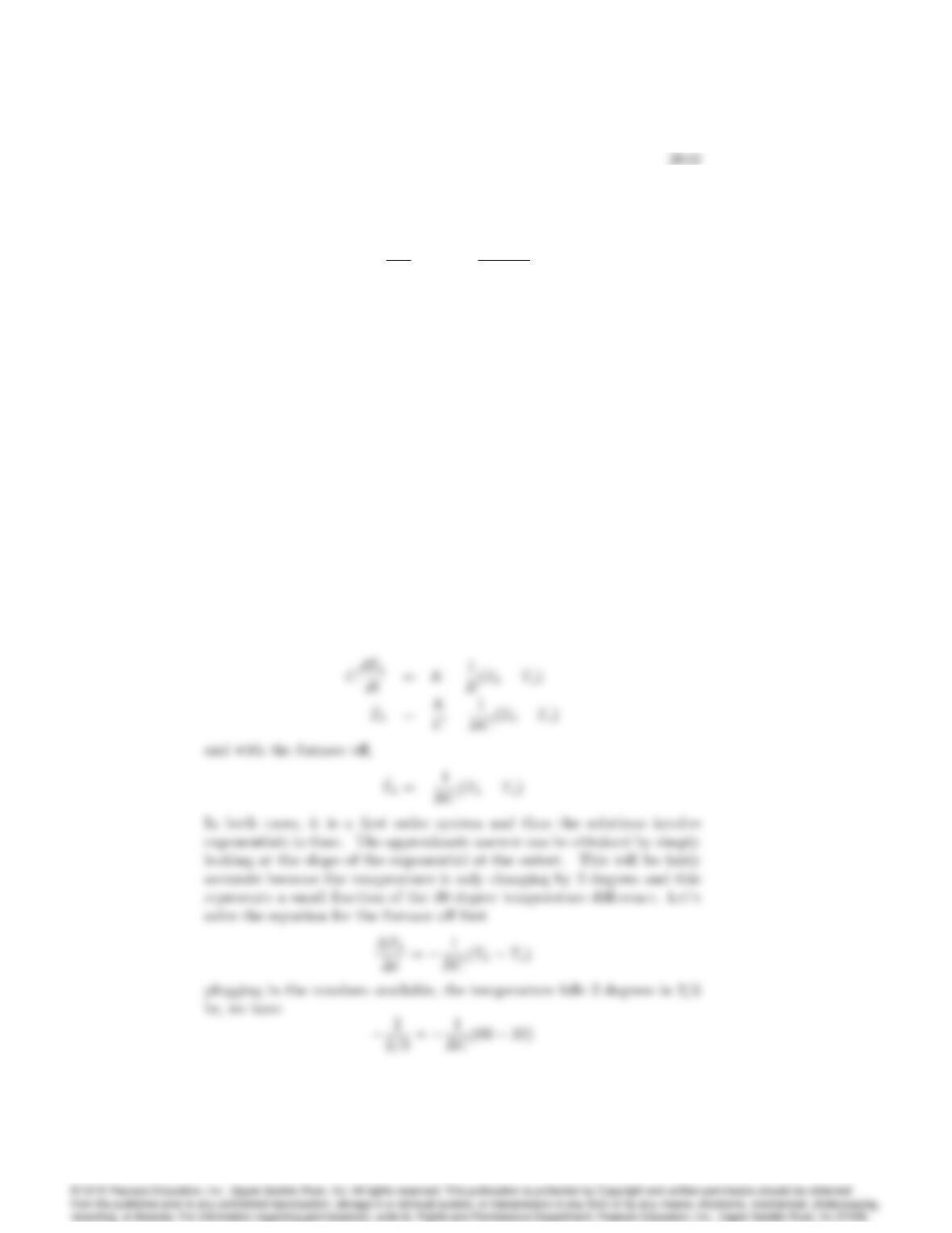
(b) At h1= 30 cm and h2= 10 cm, compute a linearized model and the
transfer function from pump ‡ow (in cubic centimeters per minute)
to h2.
(c) Repeat parts (a) and (b) assuming hole B is closed and hole A is
open. Assume that h3= 20 cm, h1>20 cm, and h2<20:cm.
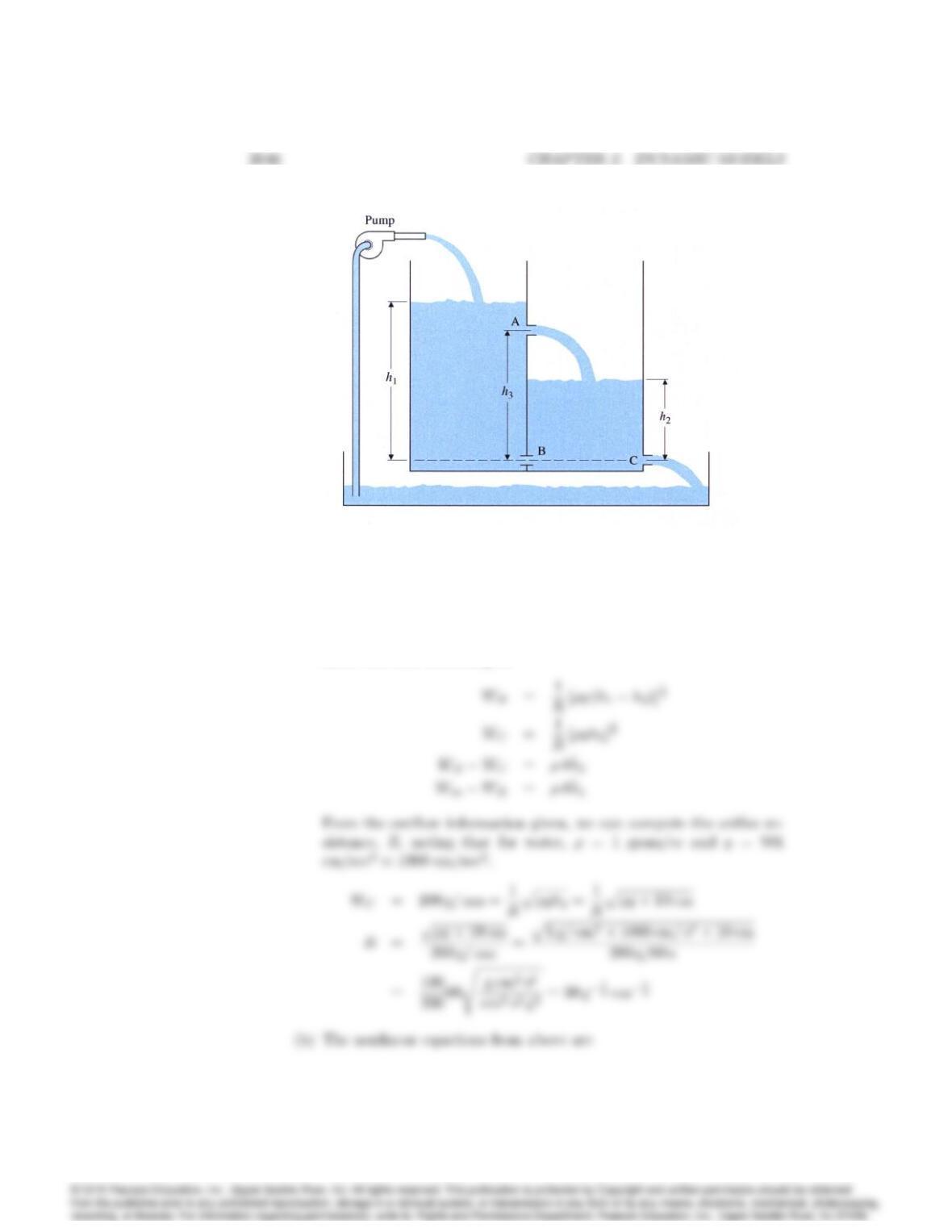
Fig. 2.60 Two-tank ‡uid-‡ow system for Problem 26
Solution:
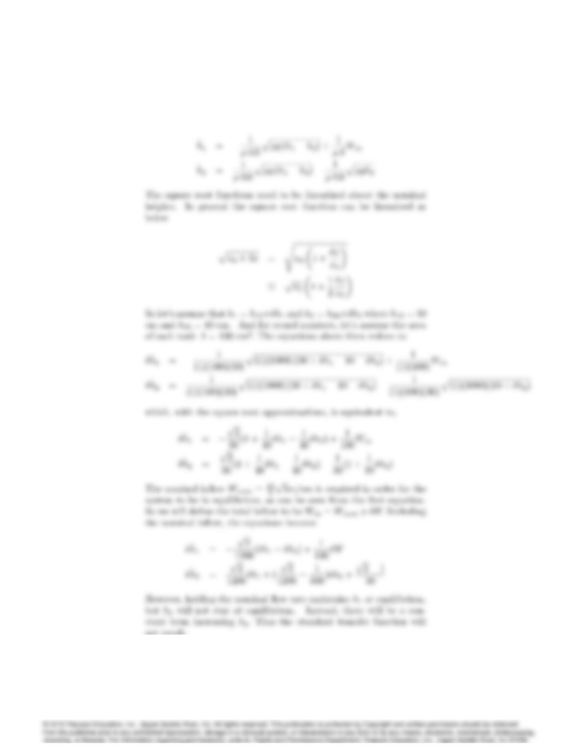
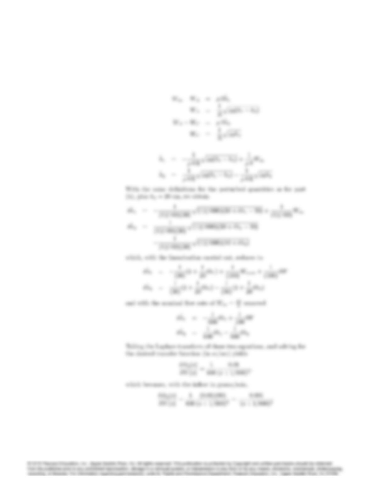
(a) Following the solution of Example 2.19, and assuming the area of
both tanks is A; the values given for the heights ensure that the
water will ‡ow according to
2047
not result.
2048 CHAPTER 2. DYNAMIC MODELS
(c) With hole B closed and hole A open, the relevant relations are
27. The equations for heating a house are given by Eqs. (2.81) and (2.82)
and, in a particular case can be written with time in hours as
CdTh
dt =Ku ThTo
R
where
(a) Cis the Thermal capacity of the house, BT U=oF
(b) This the temperature in the house, oF
(c) Tois the temperature outside the house, oF
(d) Kis the heat rating of the furnace, = 90;000 BT U=hour
(e) Ris the thermal resistance, oFper BT U=hour
(f) uis the furnace switch, =1 if the furnace is on and =0 if the furnace
is off.
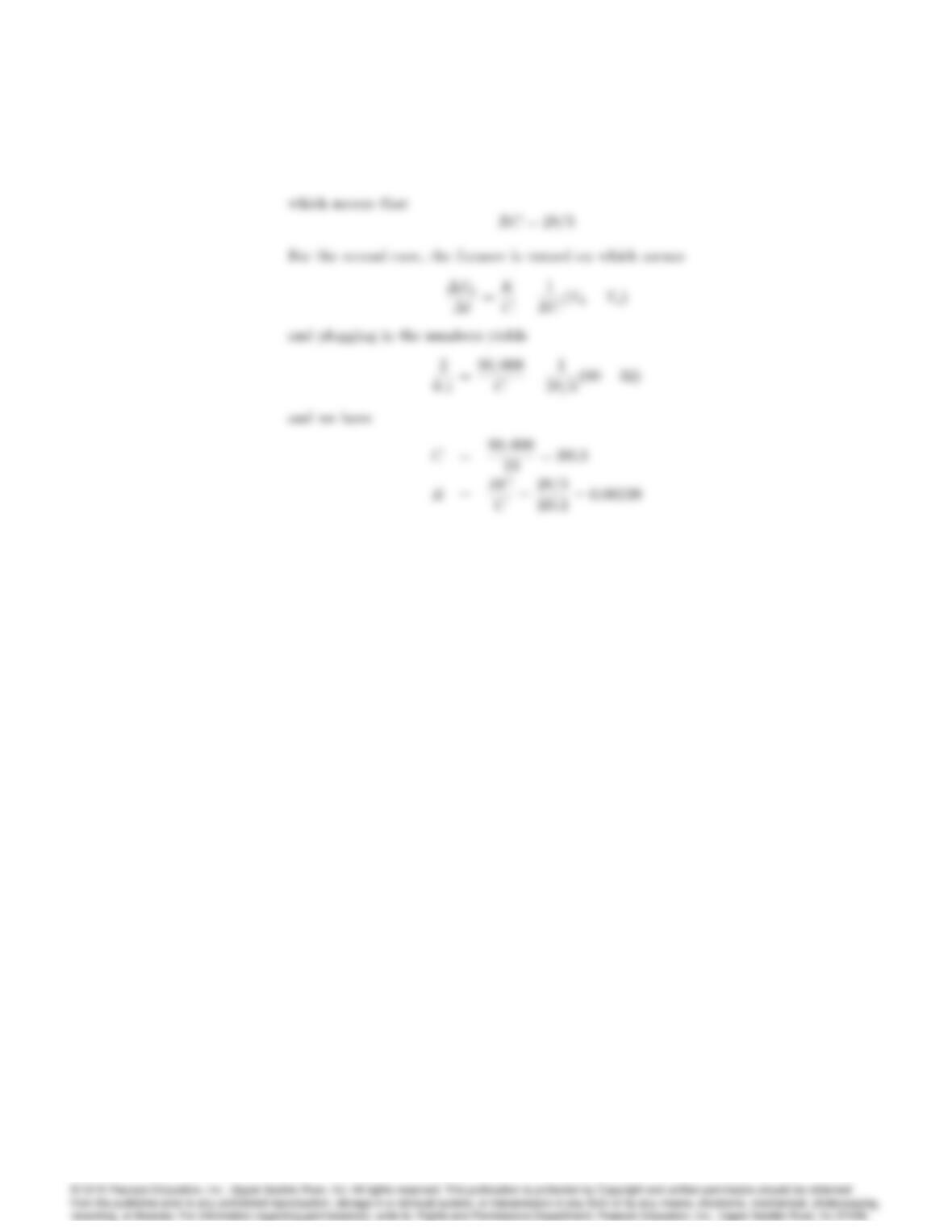
It is measured that, with the outside temperature at 32 oFand the house
at 60 oF, the furnace raises the temperature 2 oFin 6 minutes (0.1
hour). With the furnace off, the house temperature falls 2 oFin 40
minutes. What are the values of Cand Rfor the house?
Solution:
For the first case, the furnace is on which means u= 1.
2050 CHAPTER 2. DYNAMIC MODELS