
21
open slot in the Physical Device View, as shown in Figure 8-36. Turn the power
back on. Close the Router3 window.
6. Use a Fiber cable to connect the FastEthernet4/0 port on Router2 to the
FastEthernet6/0 port on Router3.
Now you’re ready to calculate the subnets you’ll use in your Packet Tracer network.
Answer the following questions:
7. You’ll need a different subnet for each connection to a router or each connection
between routers. How many subnets will you need altogether?
8. Using the formula 2n = Y, how many bits will you need to borrow from the host
portion of the IP address?
9. What will your new subnet mask be?
10. What is the magic number for these calculations?
11. How many possible hosts can each subnet have?
12. Fill in the Network ID column in Table 8-12 with the first several subnets for this
network. The first one is filled in for you. The table only covers the subnets you’ll
need for this project.
13. Fill in the Broadcast address column in Table 8-12.
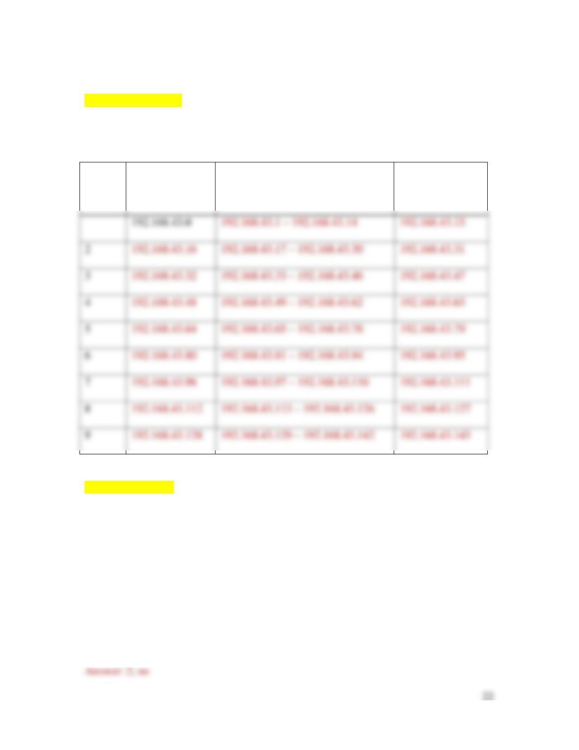
14. Fill in the Range of host addresses column in Table 8-12.
[[Begin Table 8-12]]
Table 8-12 Subnet information for Packet Tracer network
Subnet
number
Network ID
Range of host addresses
Broadcast address
2
3
4
5
6
8
9
[[End Table 8-12]]
Three of these subnets only need two host addresses, because they connect only two
routers. Let’s take the first subnet here and divide it again into three additional, smaller
subnets. Answer the following questions:
15. If you borrow one more bit from the host portion of the IP address in Subnet 1,
how many smaller subnets will this create? Is this enough?
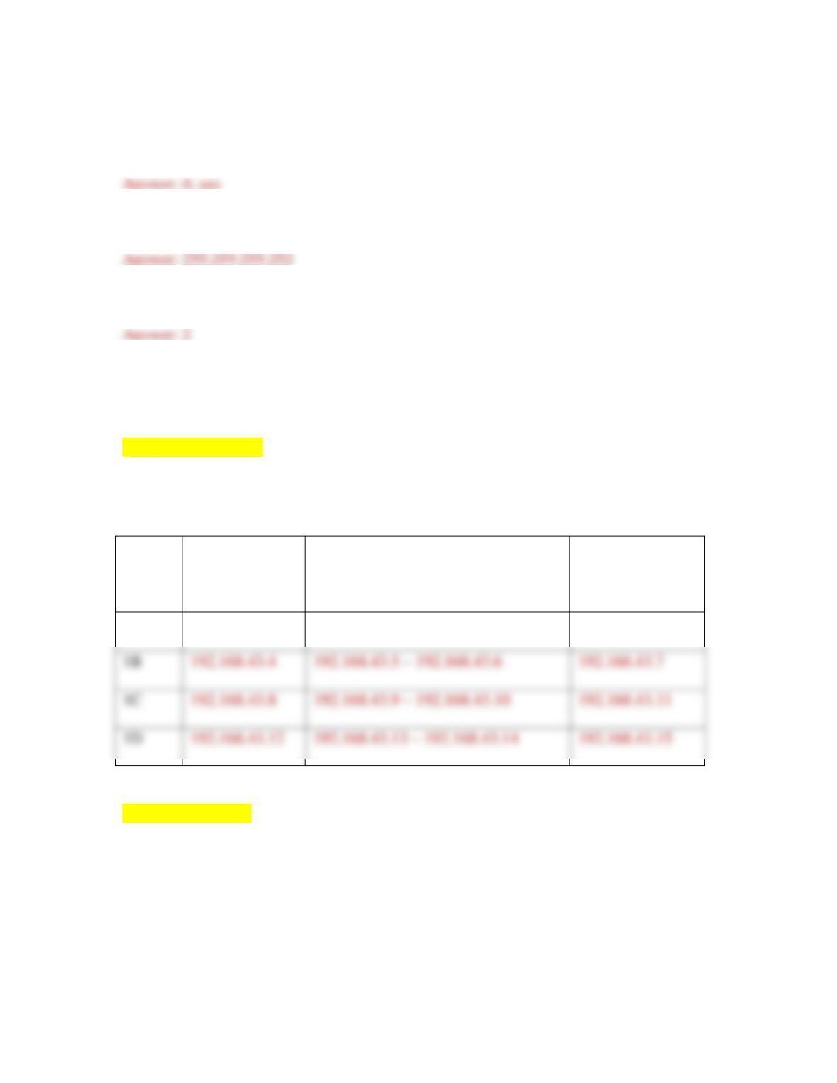
23
16. If you borrow two more bits from the host portion of the IP address in Subnet 1,
how many smaller subnets will this create? Is this enough?
17. What’s the new subnet mask for these smaller subnets?
18. How many hosts can each of these smaller subnets have?
19. Fill in Table 8-13 with the smaller subnets’ information. The first one is filled in
for you.
[[Begin Table 8-13]]
Table 8-13 Smaller subnets for router-to-router connections
Subnet
number
Network ID
Range of host addresses
Broadcast address
1A
192.168.43.0
192.168.43.1 – 192.168.43.2
192.168.43.3
1B
1C
1D
[[End Table 8-13]]
Let’s look at where each of these subnet assignments belong on your network in Packet
Tracer. Complete the following steps:
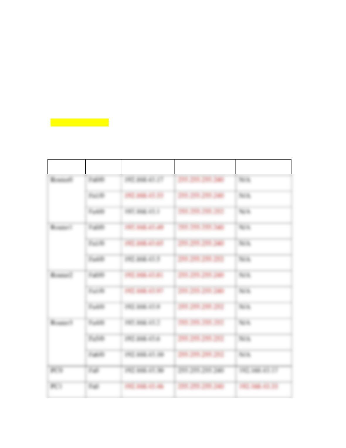
24
20. Each of the smaller subnets will be assigned to a connection between two routers.
Each router interface will be assigned a host IP address within that smaller subnet.
Notice in Table 8-14 how the IP addresses for these smaller subnets are assigned
to each router’s interfaces (Fa4/0 for Routers 0, 1, and 2, and all three interfaces
for Router3).
[[Begin Table 8-14]]
Table 8-14 IP address assignments for device interfaces
Device
Interface
IP address
Subnet mask
Default gateway
Fa0/0
192.168.43.17
N/A
Fa1/0
N/A
Fa4/0
192.168.43.1
N/A
Fa1/0
N/A
Fa4/0
192.168.43.5
N/A
Fa0/0
N/A
Fa1/0
N/A
Fa5/0
192.168.43.6
N/A
Fa6/0
192.168.43.10
N/A
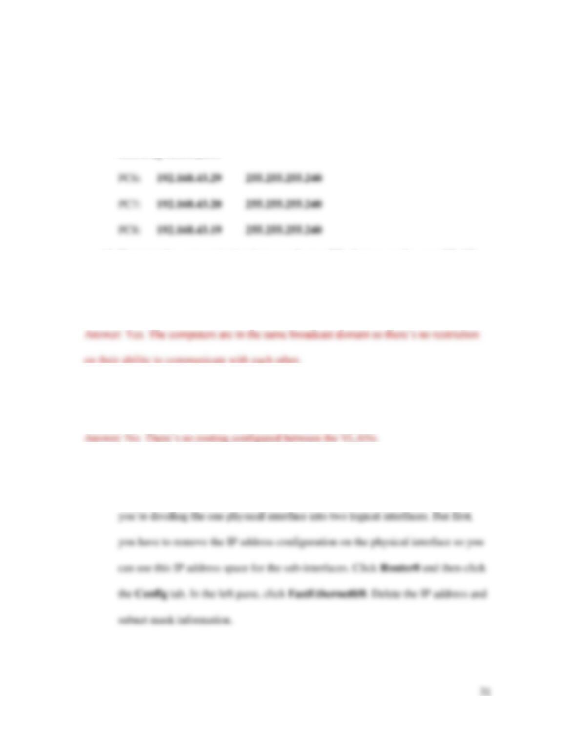
PC0
Fa0
192.168.43.30
255.255.255.240
192.168.43.17
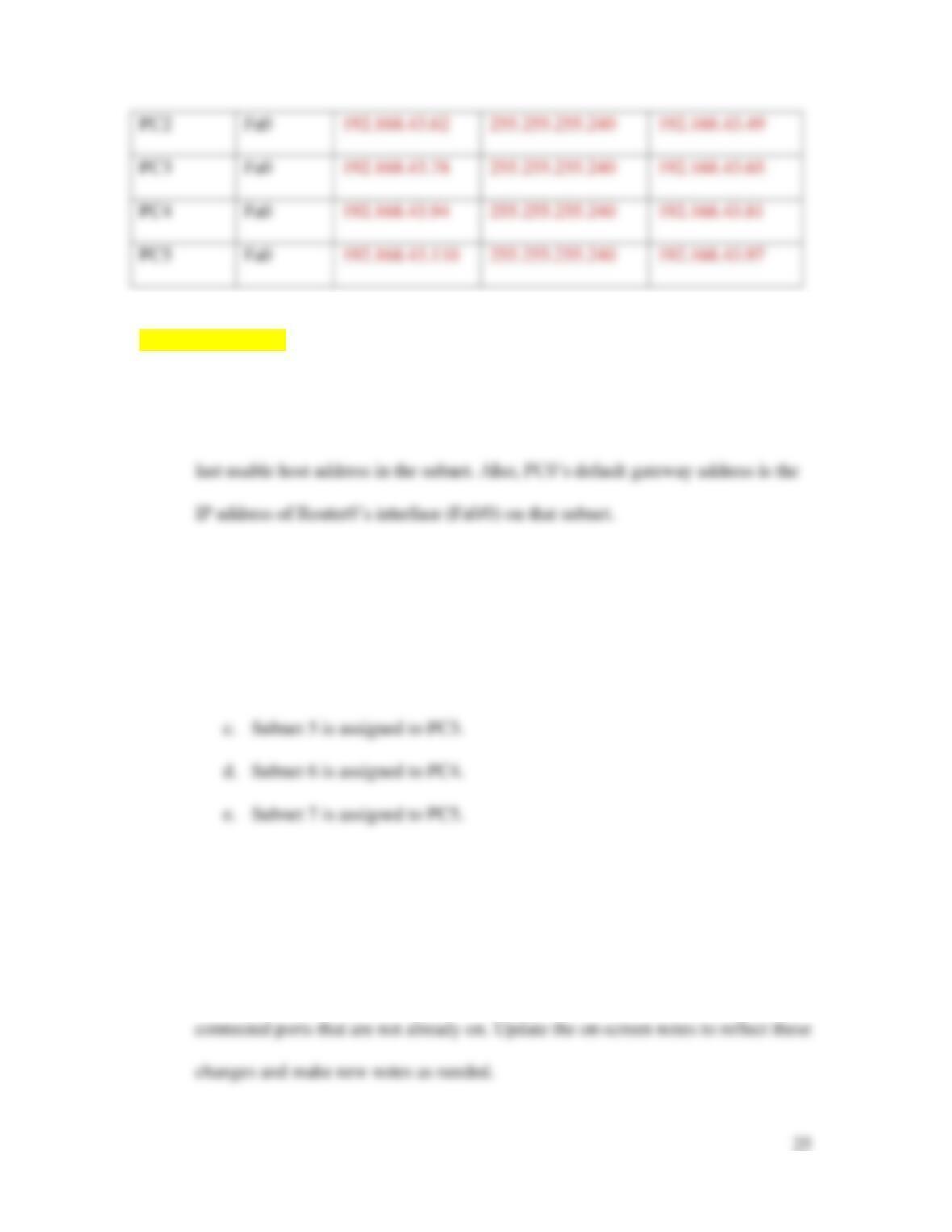
[[End Table 8-14]]
21. Subnet 2 is assigned to PC0’s subnet. Notice in Table 8-14 that PC0’s default
gateway is the first usable host address in the subnet, and PC0’s interface has the
22. Repeat this pattern and assign the following subnets to each PC, filling in the
relevant information for that workstation and its router in Table 8-14.
a. Subnet 3 is assigned to PC1.
b. Subnet 4 is assigned to PC2.
Now you’re ready to configure these subnets on your network in Packet Tracer. Complete
the following steps:
23. Click Router0 and click the Config tab. Configure each of the three connected
interfaces with the information listed for Router0 in Table 8-14, and turn on any
25. Click PC0, click the Desktop tab, and click IP Configuration. Configure the IP
Address, Subnet Mask, and Default Gateway information listed for PC0 in Table
26. Repeat Step 25 for each of the other workstations.
27. If any link does not turn green, troubleshoot the configuration to find the problem.
Most of the time, the problem is a typo or forgetting to turn on a port. After all the
links turn green, start pinging various interfaces from different workstations to
confirm all the connections are configured correctly. To run ping from any PC,
click the PC, and then click the Desktop tab. Click Command Prompt and run
your pings from here. For example, can you ping PC0 from PC5? Can you ping
all three of Router3’s interfaces from PC3? What problems did you find from
your ping tests, and how did you fix them?
27
28. Click File, Save As, and save this Packet Tracer file in a safe place for future
projects.
29. Add installation information to the Packet Tracer page on your Wikidot website,
along with any notes that you think might be helpful to you for the next Packet
Tracer project. When you’re finished, close Packet Tracer or continue to
Capstone Project 8-2.
[B HD] Capstone Project 8-2: Add VLANs to Your Packet Tracer
Network
This Capstone Project picks up where Capstone Project 8-1 left off. In this project, you
create VLANs on switches in your Packet Tracer network, and test the connections to see
Let’s begin by creating a pair of simple VLANs on Switch0. For this project, you use the
switch’s configuration interface. In Capstone Project 8-3, you’ll learn to use the CLI for
both a switch and a router. After completing Capstone Project 8-1, complete the
following steps:
1. In Packet Tracer, open your Packet Tracer file from Capstone Project 8-1.
2. On the far-left side of the workspace, add three more PCs as shown in Figure 8-
37. If you need to create more space on that side of the workspace, use the Select
tool from the Common tools bar on the right. Press and hold the mouse button and
drag the mouse pointer to select all items on the screen, release the mouse button,
then click any selected object to move the entire group.
3. Connect each of these PCs to the switch using the following interfaces and
Copper Straight-Through cables:
4. Now you’re ready to configure the switch. As you make configuration changes,
remember to watch the commands that Packet Tracer automatically generates for
29
5. Create two VLANs: one for Accounting, and one for Sales. Recall that VLAN 1
already exists as the default VLAN, so be sure to start with VLAN 2. Enter the
6. Enter the following information for the second new VLAN, and then click Add:
7. Confirm that both new VLANs appear in the middle pane. What is the full list of
VLANs now included in the middle pane?
8. You’ve created each of the VLANs, and now you need to configure ports for each
VLAN. In the left pane, click FastEthernet0/1. What mode and VLAN is this
port already configured for?
[BEGIN NOTE]
Note
If at any point you need to check which interface a particular connection is using on a
device, float your cursor over the connection. Packet Tracer will show the interface in use
on each end.
[END NOTE]
9. Make sure Access is selected, and then change the VLAN to 2:Accounting. What
command did Packet Tracer use to configure this interface for VLAN 2?
10. Repeat this process for the other three PCs connected to Switch0. Use the
following information:
11. To confirm your configurations are correct, click the CLI tab. The current prompt
should be Switch (config–if)#. This says you’re configuring a switch,
and you’re in interface configuration mode. Enter the command exit to return to
global configuration mode. The prompt should now be Switch (config)#.
Enter the command do show vlan. The output should look like Figure 8-38. If
it doesn’t, troubleshoot the steps you’ve taken so far to see what needs to be
changed. Press Tab to return to the prompt.
12. Before you leave the switch to work on the PCs, you need to save the
configurations you’ve completed so far. To do this, you need to leave global
configuration mode and use privileged EXEC mode instead. Enter the command
exit, enter the command copy run start, and then press Enter again.
13. VLANs are configured on a switch; however, you still need to configure IP
addresses on the PCs. Refer to Capstone Project 8-1 if you need help
remembering how to configure a static IP address on a PC. For this step, you’ll
initially leave all four PCs on the same subnet even though they’re on different
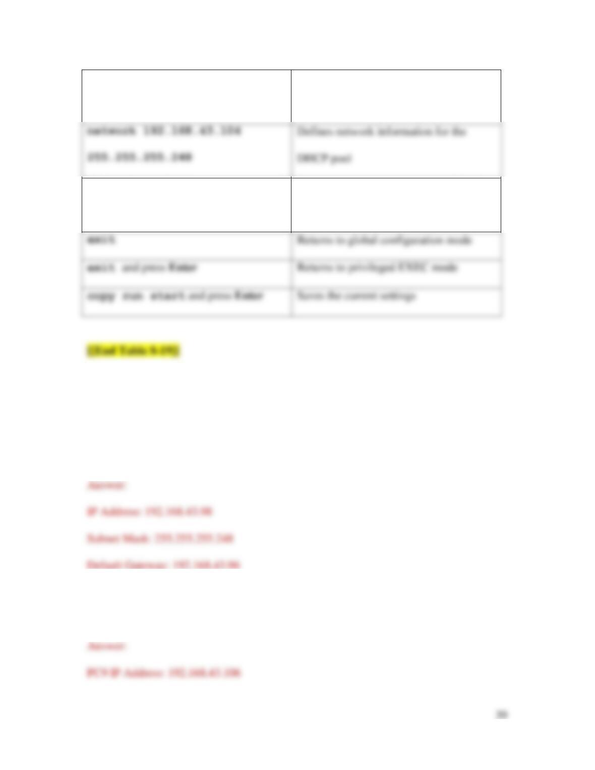
VLANs. Use 192.168.43.17 as the default gateway for all three PCs, and use the
following information:
14. First, test the communication between the two PCs that are on the same VLAN
and on the same subnet. Click PC0 and ping PC6 at 192.168.43.29. Does it work?
Why do you think this is?
15. Now ping across VLANs, which in this case, are still on the same subnet. From
PC0, ping PC7 at 192.168.43.20. Does it work? Why do you think this is?
16. Configure the router to send traffic between VLANs. To do this, you have to
configure a sub-interface on the router for each VLAN. Basically, this means
32
17. Now click the CLI tab. Enter the commands listed in Table 8-15 to configure a
sub-interface for each VLAN using two subnets of the original subnet for this
network.
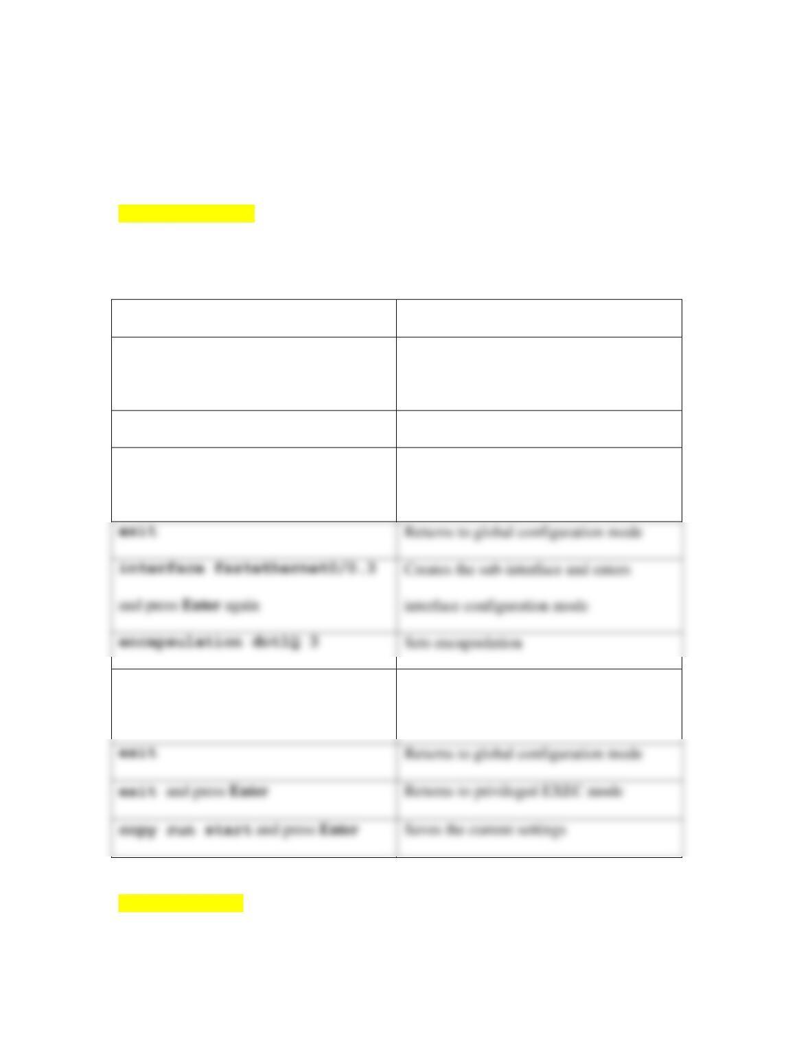
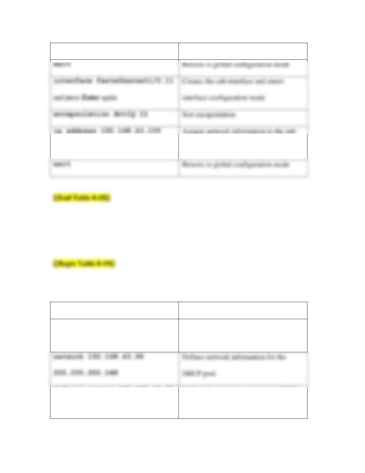
[[Begin Table 8-15]]
Table 8-15 Create sub-interfaces on the router’s physical interface
Command
Purpose
interface fastethernet0/0.2
and press Enter again
Creates the sub-interface and enters
interface configuration mode
encapsulation dot1Q 2
Sets encapsulation
ip address 192.168.43.25
255.255.255.248
Assigns network information to the sub-
interface
ip address 192.168.43.17
255.255.255.248
Assigns network information to the sub-
interface
Returns to global configuration mode
copy run start and press Enter
[[End Table 8-15]]
interface fastethernet0/0.3
Creates the sub-interface and enters
interface configuration mode
Sets encapsulation
18. Now, because you’ve adjusted the subnetting for these devices, go back to each of
the four PCs and update their IP configuration information to reflect the correct
subnet and the correct default gateway, as needed. Also update your notes for all
involved devices as needed. Ping from PC0 to PC7. Does it work now? Why do
you think this is?
19. Click File, Save as, and save this Packet Tracer file in a safe place for future
projects.
20. Add installation information to the Packet Tracer page on your Wikidot website,
along with any notes that you think might be helpful to you for the next Packet
Tracer project. When you’re finished, close Packet Tracer or continue to
Capstone Project 8-3.
Capstone Project 8-3: Configure VLANs in Packet Tracer Using the
CLI
This Capstone Project picks up where Capstone Project 8-2 left off. In Capstone Project
8-2, you created two VLANs on one switch. For the most part, when possible, you used
the Configuration GUI to make these changes. This time, let’s work on a different subnet,
34
1. In Packet Tracer, open your Packet Tracer file from Capstone Project 8-2.
2. Scroll to the right side of the network. Add a switch and three more PCs,
positioned as shown in Figure 8-39.
3. Connect each of the devices to the following interfaces using Copper Straight-
Through cables:
• Switch5 (FastEthernet0/24) to Switch6 (FastEthernet0/24)
• PC9 to Switch5 (FastEthernet0/3)
• PC10 to Switch6 (FastEthernet0/1)
• PC11 to Switch6 (FastEthernet0/3)
Technically, you should have used a Crossover cable to connect the two switches
to each other. However, the link worked. Why do you think this is?
4. Configure two VLANs with one PC from each switch on each VLAN. Click
Switch5 and click the CLI tab. Press Enter.
5. Here, you’re starting out in user EXEC mode. To access privileged mode, which
allows you to carry out administrative tasks, enter the command enable.
7. Enter the commands listed in Table 8-16 to create and name two VLANs.
[[Begin Table 8-16]]
35
Table 8-16 Create and name two VLANs
Command
Purpose
vlan 10
Creates VLAN 10 and enters VLAN configuration mode for that VLAN
name HR
Assigns VLAN 10 the name HR
[[End Table 8-16]]
[BEGIN NOTE]
Note
Spaces are not allowed in the VLAN name. The VLAN name is not used by other
switches or nodes, but is a convenient reference for network administrators.
[END NOTE]
8. Enter the commands listed in Table 8-17 to assign a port to each of the two
VLANs. When you’re finished, close the switch’s window.
[[Begin Table 8-17]]
Table 8-17 Assign a port to each VLAN
Command
Purpose
interface fastethernet0/1
Enters interface configuration mode for
vlan 11
Creates VLAN 11 and enters VLAN configuration mode for that VLAN
name IT
Assigns VLAN 11 the name IT
Returns to global configuration mode
FastEthernet0/1
switchport mode access
Sets access mode for this port
switchport access vlan 10
Assigns this port to VLAN 10
exit
Returns to global configuration mode
interface fastethernet 0/3
Enters interface configuration mode for
FastEthernet0/3
switchport mode access
Sets access mode for this port
switchport access vlan 11
Assigns this port to VLAN 11
exit
Returns to global configuration mode
interface fastethernet0/24
Enters interface configuration mode for
FastEthernet0/24
exit
Returns to global configuration mode
Switch5 only: interface
fastethernet0/2
Enters interface configuration mode for
FastEthernet0/2
Switch5 only: switchport mode
Sets trunk mode for this port, which is
37
[[End Table 8-17]]
9. Repeat Steps 4 – 8 for Switch6.
10. Click Router2 and then click the Config tab. In the left pane, click
11. Click the CLI tab. Enter the commands listed in Table 8-18 to configure a sub-
[[Begin Table 8-18]]
Table 8-18 Create two sub-interfaces, each with their own subnet
Command
Purpose
enable
Enters privileged EXEC mode
configure terminal
Enters global configuration mode
interface configuration mode
encapsulation dot1Q 10
Sets encapsulation
ip address 192.168.43.97
exit and press Enter
38
255.255.255.248
interface
255.255.255.248
interface
exit
Returns to global configuration mode
12. Next, configure DHCP on the router. Enter the commands listed in Table 8-19.
When you’re finished, close the router’s window.
Table 8-19 Configure DHCP pools on a router
Command
Purpose
ip dhcp pool FIRST
Creates the first DHCP pool and enters
DHCP configuration mode
DHCP pool
default–router 192.168.43.97
Defines the default router for the DHCP
pool
exit
Returns to global configuration mode
interface configuration mode
encapsulation dot1Q 11
Sets encapsulation
ip address 192.168.43.105
Assigns network information to the sub-
ip dhcp pool SECOND
Creates the second DHCP pool and enters
DHCP configuration mode
network 192.168.43.104
Defines network information for the
DHCP pool
default–router
192.168.43.105
Defines the default router for the DHCP
pool
Returns to global configuration mode
13. Test your DHCP configurations. Click on PC5, Desktop, and IP Configuration.
This PC is currently configured with a static IP address. Select DHCP and wait
while the DHCP request is resolved. What network information was assigned to
PC5?
14. Repeat Step 13 for the other three PCs on these VLANs. What network
information was assigned to PC9, PC10, and PC11?
15. Ping PC9 from PC5. Does it work? Why do you think this is?
16. Ping PC10 from PC5. Does it work? Why do you think this is?
17. Click File, Save as, and save this Packet Tracer file in a safe place for future
18. Add installation information to the Packet Tracer page on your Wikidot website,