1
Chapter 10
Security in Network Design
Applying Concepts: Protocol Synopsis
Each of the protocols covered in this and previous chapters plays an important role in
securing transmissions between devices and locations. It’s important to have the big
picture in mind regarding how these protocols interact with each other and the roles they
play in various parts of the system when troubleshooting connectivity and security issues.
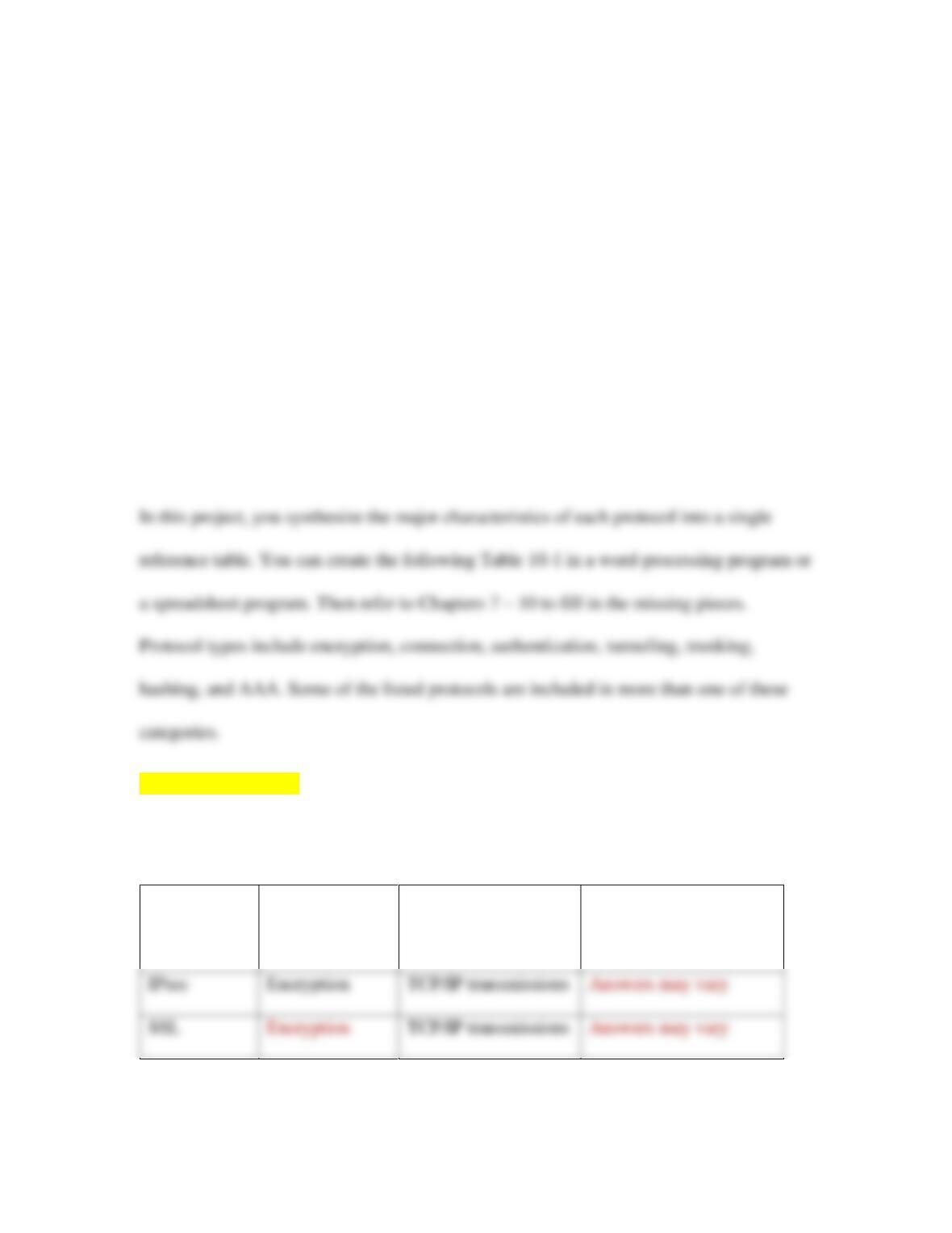
[[Begin Table 10-1]]
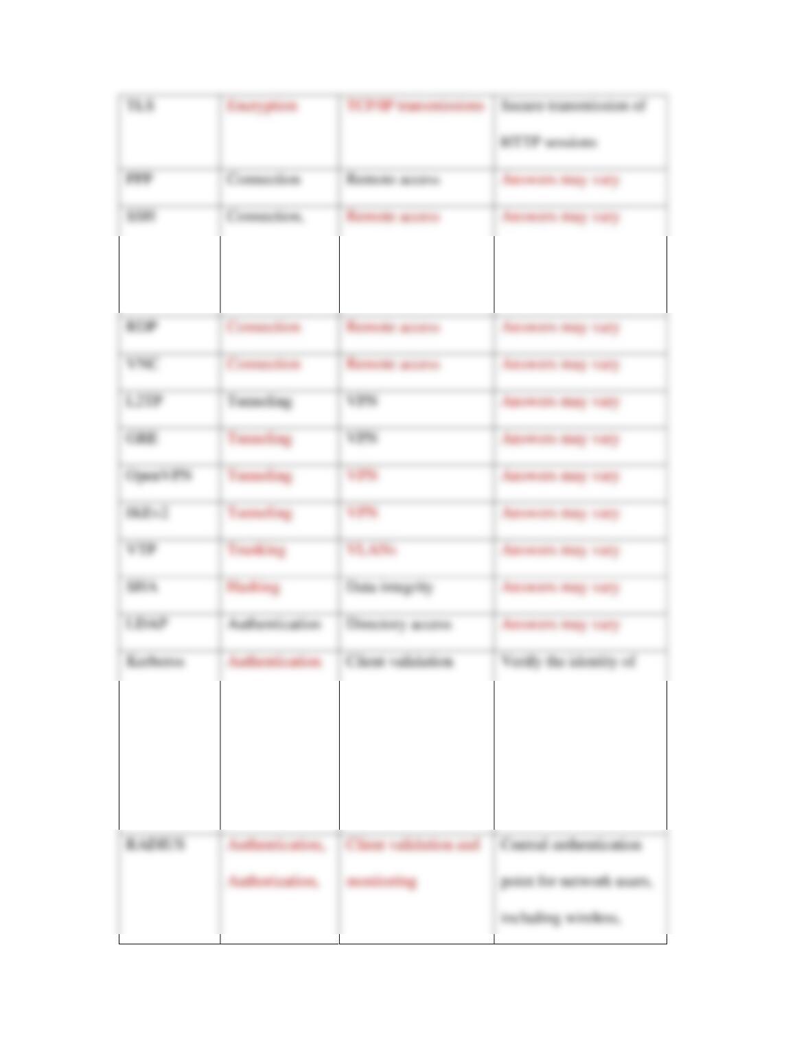
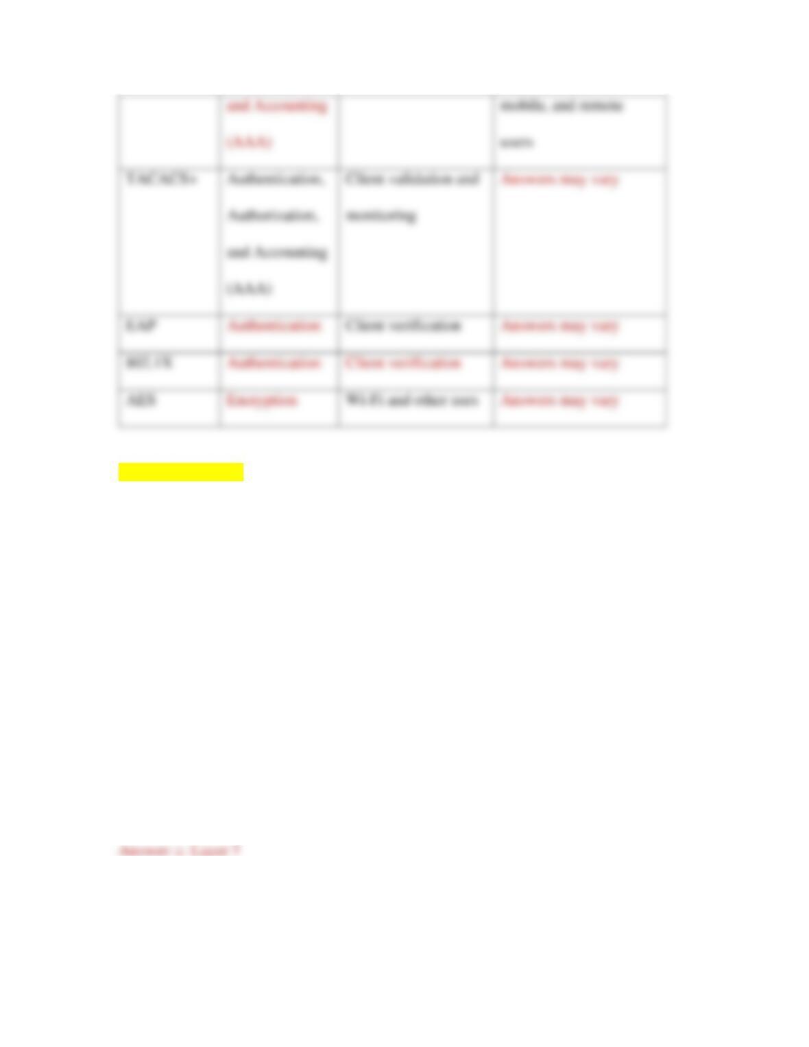
Table 10–1 Notable encryption and authentication methods
Security
method
Type
Primary use(s)
Notes
2
Authentication,
Encryption
RDP
L2TP
Tunneling
VPN
GRE
VPN
OpenVPN
IKEv2
VTP
SHA
Data integrity
LDAP
Authentication
Directory access
clients and securely
exchange information
after a client logs on to a
system
Secure transmission of
Connection
Remote access
3
[[End Table 10-1]]
Review Questions
1. At what layer of the OSI model do proxy servers operate?
a. Layer 3
b. Layer 2
c. Layer 7
d. Layer 4
2. Which of the following ACL commands would permit web-browsing traffic from
any IP address to any IP address?

a. access–list acl_2 deny tcp any any
b. access–list acl_2 permit http any any
c. access–list acl_2 deny tcp host 2.2.2.2 host
3.3.3.3 eq www
d. access–list acl_2 permit icmp any any
3. What kind of firewall blocks traffic based on application data contained within the
packets?
a. Host-based firewall
b. Content-filtering firewall
c. Packet-filtering firewall
d. Stateless firewall
4. Which of the following features is common to both an NGFW and traditional
firewalls?
a. Application Control
b. IDS and/or IPS
c. User awareness
d. User authentication

5
5. Which NGFW feature allows a network admin to restrict traffic generated by a
specific game?
a. Content filter
b. User awareness
c. Context awareness
d. Application awareness
6. What software might be installed on a device in order to authenticate it to the
network?
a. Operating system
b. Security policy
c. NAC (network access control)
d. Agent
7. Which of the following is not one of the three AAA services provided by
RADIUS and TACACS+?
a. Authentication
b. Authorization
c. Access control
d. Accounting

6
8. What feature of Windows Server allows for agentless authentication?
a. AD (Active Directory)
b. ACL (access control list)
c. IDS (intrusion detection system)
d. Network-based firewall
9. Which command on an Arista switch would require an SNMP notification when
too many devices try to connect to a port?
a. mac–limit
b. switchport port–security
c. storm–control
d. shutdown
10. Active Directory and 389 Directory Server are both compatible with which
directory access protocol?
a. LDAP
b. RADIUS
c. Kerberos
d. AES

7
11. What are the two primary features that give proxy servers an advantage over
NAT?
12. What kinds of issues might indicate a misconfigured ACL?
13. Any traffic that is not explicitly permitted in the ACL is ___________, which is
called the ____________________________.
14. What’s the essential difference between an IPS and an IDS?
15. What causes most firewall failures?
16. Why is a BPDU filter needed at the demarc?
17. Why do network administrators create domain groups to manage user security
privileges?

8
18. Only one ___________________ exists on a network using STP.
19. What kind of ticket is held by Kerberos’ TGS?
20. EAPoL is primarily used with what kind of transmission?
Hands-On Projects
Project 10-1: Configure RADIUS in Packet Tracer
In Chapter 6, Capstone Project 6-1, you downloaded and installed Packet Tracer. You’ve
continued to build on your Packet Tracer network in Chapters 7, 8, and 9. In this project,
you’ll configure RADIUS on a new Packet Tracer network. Complete the following
steps:
[BEGIN NOTE]
Note
If you’ve not been completing the Capstone Projects, prepare for this project by
completing Capstone Project 6-1 first.
[END NOTE]
9
1. Open Packet Tracer. From the Network Devices, Wireless Devices menu, insert
2. On the wireless router’s Config tab, set its LAN-facing IP address to
3. From the End Devices menu, insert a generic laptop.
4. On the laptop’s Physical tab, replace the Ethernet network module with a wireless
module:
a. Click the laptop’s power button to turn off the laptop.
5. Now let’s set up some security parameters on the wireless router:
a. On the wireless router’s Config tab, select WPA2 authentication.
b. Set the RADIUS server’s IP address to 192.168.5.2.
c. Set the shared secret to networkplus.
d. Make sure the encryption type is AES.
e. What has happened to your network devices? Why do you think this is?
10
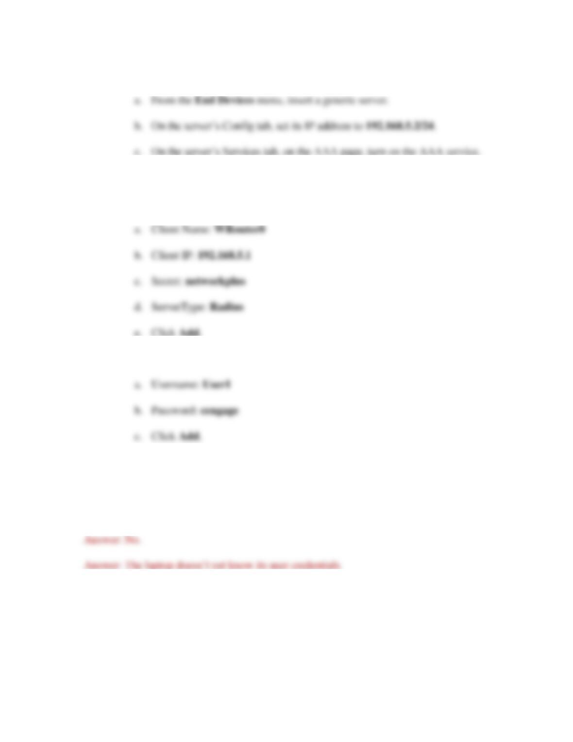
6. To solve this problem, you need to create a RADIUS server:
7. In the Network Configuration section, add a new client with the following
information:
8. In the User Setup section, add a new user with the following information:
9. Using a Copper Straight-Through cable, connect the server’s FastEthernet0 port
to the wireless router’s Ethernet 1 port. Has the wireless connection been re–
established? Why do you think this is?
10. On the laptop’s Config tab, on the Wireless0 page, change the following settings:
a. Authentication: WPA2
b. User ID: User1

11
c. Password: cengage
d. Close the laptop’s configuration window, and the wireless connection
should re-establish within a minute or two.
e. You didn’t configure the laptop’s user information on the wireless router.
How did the router know to accept the laptop as a wireless client?
11. Save your project for use in Project 10-2.
12. Make some notes on your Wikidot website about your activities in Packet Tracer
for this project.
Project 10-2: Secure a Basic Wireless Network in Packet Tracer
This project picks up where Project 10-1 left off. In this project, you explore more of the
wireless security options available on a wireless router. Using the Packet Tracer network
you created in Project 10-1, complete the following steps:
1. On the wireless router’s GUI tab, what is the current DHCP pool? What is the
client lease time?
2. On the Wireless > Basic Wireless Settings page, change the default SSID to
HappyVintage.

3. On the Wireless > Wireless Security page, WPA2 Enterprise is already selected.
What other security mode option(s) do you have? Which of these security modes
is the most secure?
4. AES encryption is selected. What other encryption option(s) do you have? Which
of these encryption options is most secure?
5. Close the wireless router’s configuration window. What changed on your
network? Why do you think this is?
6. On the laptop’s Config tab, on the Wireless0 page, change the SSID to
HappyVintage. What happens on your network?
7. Save your project for future reference.
8. Make some notes on your Wikidot website about your activities in Packet Tracer
for this project.

13
Project 10-3: Configure ACLs in Packet Tracer
In this project, you will create a new network in Packet Tracer, configure an ACL on the
router, and then test the connections between devices. Complete the following steps:
1. Create a Packet Tracer network with one 1941 router, two 2960 switches, and
four PCs, and create all the needed connections with Copper Straight-Through
cables, as shown in Figure 10-33. Connect the switches to the router using
GigabitEthernet connections.
2. The links between PCs and switches should come up automatically. On the
router’s Config tab, configure each GigabitEthernet interface as follows:
a. Turn the port on.
b. Assign a Class C IP address with a /24 subnet mask.
3. On each PC, configure an IP address, subnet mask, and default gateway within the
appropriate subnet for the router interface it’s connected to. For example, if you
used 192.168.2.1/24 for Gi0/0 on the router, you could use 192.168.2.10/24 with a
default gateway of 192.168.2.1 for one of the PCs on that subnet. As you go,
place a note on the screen for each configured interface so it will be easier for you
to keep track of IP address assignments later in this project.
4. Make sure each of the PCs can successfully ping each of the other PCs.
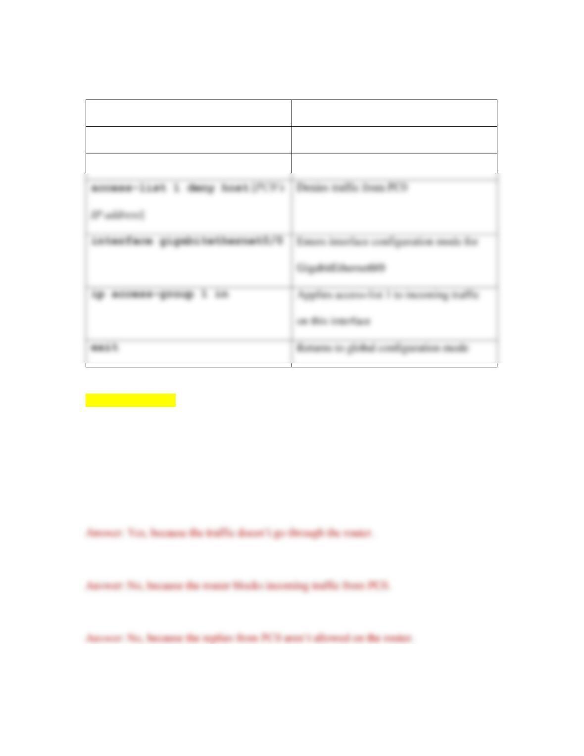
5. On the router’s CLI tab, press Enter, then enter the commands from Table 10-2.
14
Table 10-2 Create an ACL on a router
Command
Purpose
enable
Enters privileged EXEC mode
configure terminal
Enters global configuration mode
[[End Table 10-2]]
6. So far, you’ve blocked traffic coming to the router’s GigabitEthernet0/0 interface
from PC0. Let’s test your work:
a. From PC0, ping PC1. Does it work? Why do you think this is?
b. From PC0, ping PC2. Does it work? Why do you think this is?
c. From PC2, ping PC0. Does it work? Why do you think this is?
d. From PC2, ping PC1. Does it work? Why do you think this is?
GigabitEthernet0/0
on this interface
exit
Returns to global configuration mode