UNIT 38 REVIEW QUESTIONS ANSWER KEY GO BACK TO INDEX
38-1) List the different types of electrical diagrams used by HVACR manufacturers.
a. ladder diagram
b. schematic diagram
38-2) Which diagram types are most useful for understanding the operation of the unit?
38-3) Describe the concept behind ladder diagrams?
38-4) What information does a point to point diagram give the technician?
38-5) What is the difference between a load and a control?
38-6) What other diagrams are similar to point to point diagrams?
38-7) Why are relay coils and contacts not shown in the same place on a schematic
diagram?
38-8) What information does a factual diagram give that a ladder diagram does not give?
132
38-9) How is field wiring distinguished from factory wiring on most diagrams?
38-10) How is line voltage wiring distinguished from low voltage wiring on
some diagrams?
38-11) What is a system’s sequence of operation?
38-12) Which types of diagrams are best for determining a system’s sequence
of operation?
38-13) Why do many manufacturers provide both schematic and pictorial
wiring diagrams on their equipment?
38-14) What is the purpose of a component location diagram?
38-15) Why do most manufacturers supply more than one type of diagram with
their equipment?
38-16) Draw symbols for the following switches:
a. Close on rise thermostat
b. Open on rise thermostat
c. Close on rise pressure switch
d. Open on rise pressure switch
38-17) What are the two manual switches found on most thermostats?
38-18) Why are schematic diagrams often not true ladder diagrams?
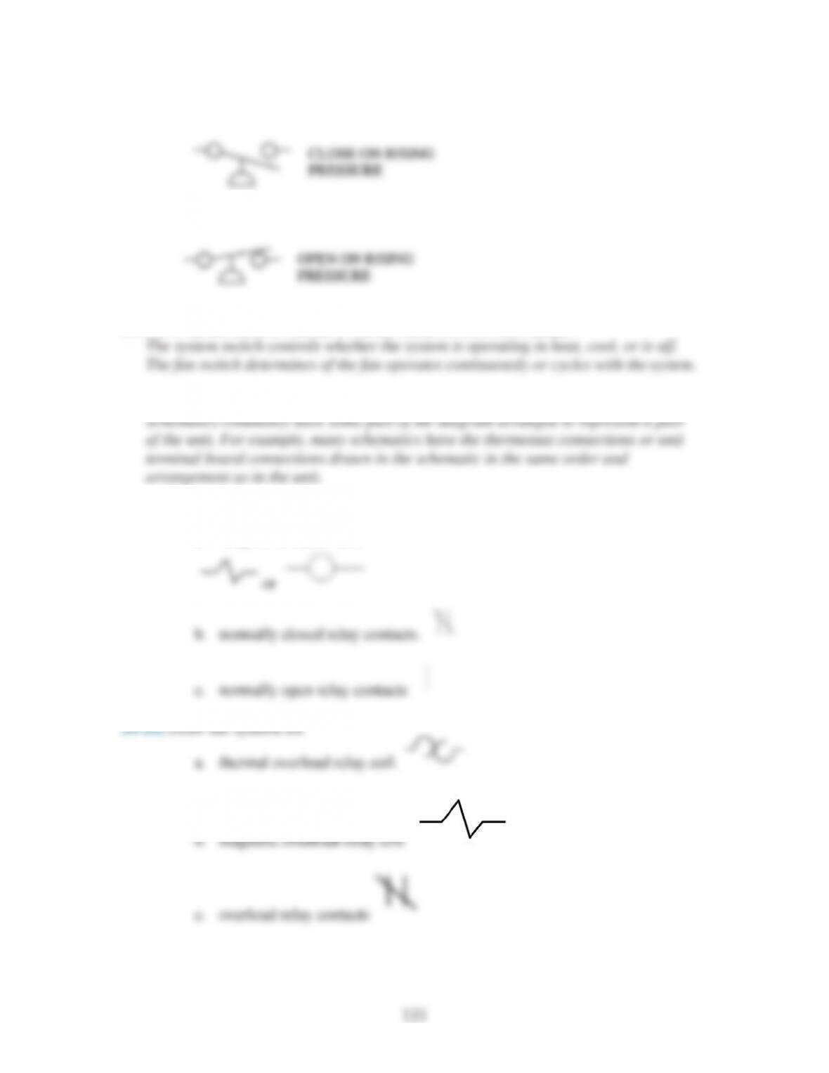
38-19) Draw the symbols that are used to represent
a. relay or contactor coil.
134
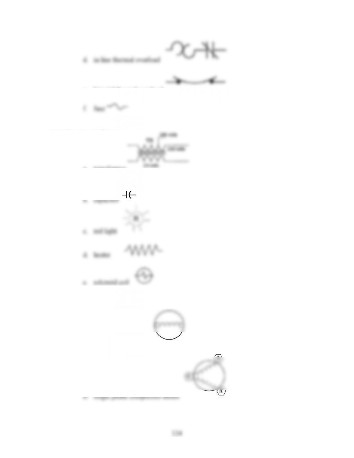
d. in line thermal overload
e. bimetal thermal overload
38-21) Draw the symbol for
a. transformer
38-22) Draw the symbol for
a. shaded pole motor
135
c. three phase motor
38-23) In Figure 38-37, what color wire is connected to the compressor start terminal S?
38-24) In Figure 38-37, how does the HP switch protect the compressor?
38-25) In Figure 38-37, what is the purpose of the red wire on the transformer primary?
38-26) In Figure 38-37, what type of device is the IFC?
38-27) In Figure 38-37, where is line voltage connected to the unit?
38-28) In Figure 38-37, what controls the outdoor fan motor OFM?
38-29) In Figure 38-48, what does the M coil control?
38-30) In Figure 38-48, what type of motor is the indoor fan motor?