ANSWER KEY for the LABORATORY MANUAL GO BACK TO INDEX
Some of the newly developed refrigerants may have zero ozone depletion potential,
however all the refrigerants will have some value for global warming.
The high and low side test pressures set the highest and lowest operable limits for the unit.
The unit should always be operated below these limits.
Pure refrigerants and most azeotropes can be used in either the liquid or vapor form.
Zeotropes sometimes called near azeotropes should leave the cylinder as a liquid only.
The hazards for working with the refrigerants should be detailed in the refrigerant Safety
LAB 17.2 IDENTIFYING REFRIGERANT LUBRICANTCHARACTERISITICS
The results for this lab will vary depending on the three types of refrigeration lubricant
examined. Different types of refrigerant oil are: mineral, polyalkylene Glycol (PAG),
Polyol Ester (POE), Alkyl Benzene (AB), and Polyvinylether (PVE).
You should select a specific group of lubricants for this lab prior to the beginning of the
LAB 18.1 SOLENOID VALVES
LAB 18.2 SETTING AN EVAPORATOR PRESSURE REGULATOR
296
LAB 18.3 IDENTIFYING ACCESSORIES
LAB 18.4 INSTALLING ACCESSORIES
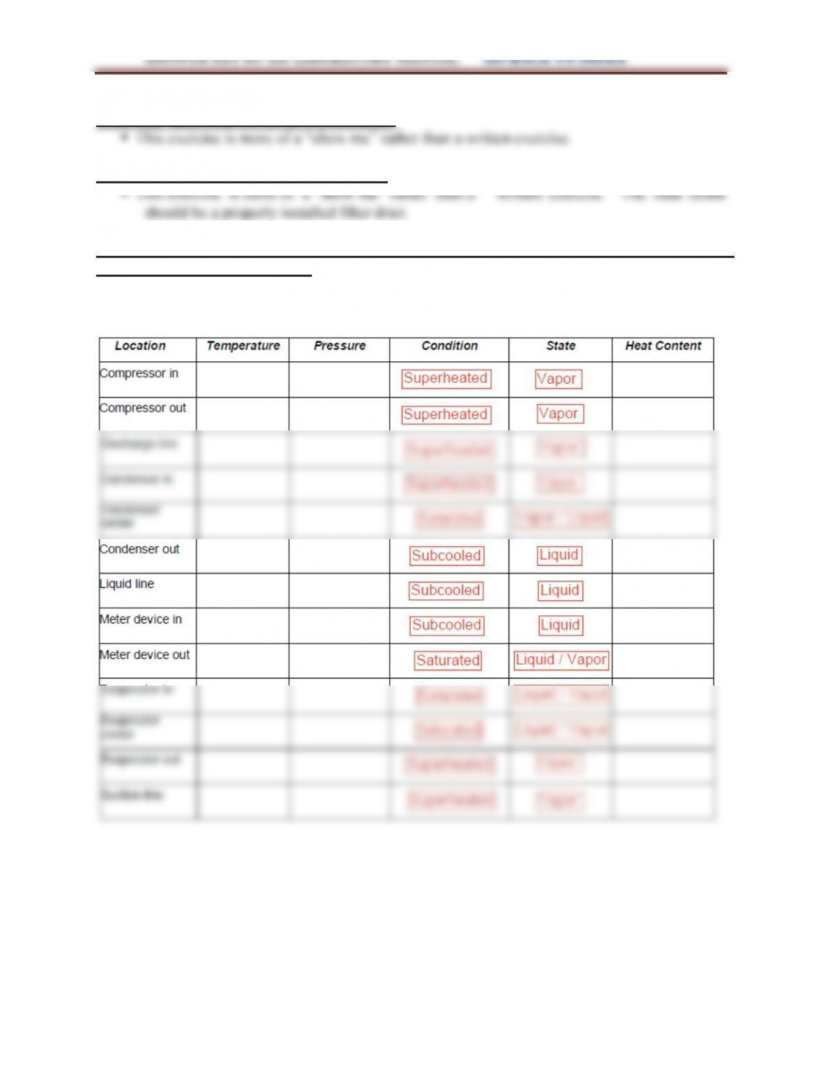
LAB 19.1 DESCRIBE THE REFRIGERATION SYSTEM CHARACTERISTICS USING A
REFRIGERATION TRAINER
The measured values for this lab will vary depending on the type of trainer used, the type
of refrigerant in the trainer and the operating conditions at the time the measurements are
taken.
297
ANSWER KEY for the LABORATORY MANUAL GO BACK TO INDEX
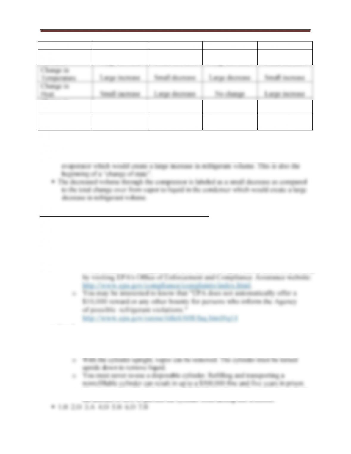
Type of Change Compressor Condenser Metering Device Evaporator
Change in
Pressure
Large increase
Small decrease
Large decrease
Small decrease
Change in
State
No change
Condensation
Evaporation
Evaporation
Change in
Volume
Small decrease
Large decrease
Small increase
Large increase
Results may vary slightly as some refrigeration trainers are designed with a minimal
pressure drop through the evaporator or condenser.
The increased volume through the metering device is due to the creation of “flash gas”.
This is labeled as a small increase as compared to the total change over to vapor in the
LAB 20.1 DISPOSABLE REFRIGERANT CYLINDERS
Step 1
oIt is against the law to knowingly release refrigerants while repairing appliances.
oJuly 1, 1992
oYes. November 14, 1994
o$37,500 per incident per day
o
If you suspect or witness unlawful releases of refrigerant or other violations
of the Clean Air Act regulations, you can file a report easily and anonymously
Step 2
o125°F
oDisposable cylinders are checked upon manufacture and do not fall under the
same guidelines as refillable cylinders.
oThey have a frangible disk (rupture disk) built into them with a restriction to limit
the amount of flow to prevent the cylinder from turning into a missile.
298
ANSWER KEY for the LABORATORY MANUAL GO BACK TO INDEX
LAB 20.2 REFILLABLE REFRIGERANT RECOVERY CYLINDERS
The answers for this lab will vary depending on the size recovery cylinder used.
There are two valves located on the top of the recovery cylinder. One valve is labeled for
liquid and the other is labeled for gas. The cylinder does not need to be turned upside
LAB 20.3 REFRIGERANT CYLINDERS
LAB 21.1 REFRIGERANT GAUGE MANIFOLDS
The answers for this lab will vary depending on the type of gauge manifold used.
LAB 21.2 REFRIGERANT EQUIPMENT FAMILIARIZATION
LAB 22.1 IDENTIFYING FITTINGS
The results for this lab will vary depending on the types of fittings examined.
LAB 22.2 FLARING
LAB 22.3 SWAGING
299
ANSWER KEY for the LABORATORY MANUAL GO BACK TO INDEX
LAB 23.1 SOLDERING COPPER PIPE
LAB 23.2 BRAZING
LAB 23.3 LIGHTING THE TORCH
LAB 23.4 SOLDERING COPPER TUBING
LAB 23.5 OXY-ACETYLENE TORCH SAFETY
LAB 23.6 BRAZING
LAB 25.1 SCHRADER CORE REPLACEMENT
LAB 25.2 INSTALLING PIERCING VALVES
LAB 25.3 EXAMINING SERVICE VALVES
They are called service valves because they can be used to access the system for
servicing such as checking pressures, adding refrigerant, etc.
The valve has a protective cap to reduce the possibility of leakage along the valve
300
ANSWER KEY for the LABORATORY MANUAL GO BACK TO INDEX
LAB 25.4 SERVICE VALVE INSPECTION
LAB 25.5 INSTALLING GAUGES ON SCHRADER VALVES
The answers for this lab will vary depending on the refrigeration systems operating
LAB 26.1 RECOVERY UNIT
The answers for this lab will vary depending on the recovery unit type
If the recovery unit has a fan switch, then this is used for the air cooled condenser built inot
LAB 26.2 REFRIGERANT VAPOR RECOVERY
LAB 26.3 PUSH-PULL REFRIGERANT RECOVERY
LAB 26.4 LIQUID RECOVERY SYSTEM DEPENDENT PASSIVE
LAB 26.5 PACKAGED UNIT RECOVERY
LAB 26.6 SPLIT SYSTEM RECOVERY
301
ANSWER KEY for the LABORATORY MANUAL GO BACK TO INDEX
LAB 26.7 SYSTEM PUMPDOWN
LAB 27.1 ELECTRONIC LEAK DETECTOR
Most refrigerants are heavier than air (ammonia is lighter) so the probe should be
LAB 27.2 HALIDE TORCH LEAK DETECTOR
The flame should be a light blue color when not exposed to refrigerants.
LAB 27.3 TESTING WITH NITROGEN AND A TRACE GAS
LAB 27.4 DETECTING LEAKS USING NITROGEN AND SOAP BUBBLES
LAB 27.5 DETECTING LEAKS USING ULTRASONIC LEAK DETECTOR
LAB 27.6 DETECTING LEAKS USING A HALIDE TORCH
LAB 27.7 DETECTING LEAKS USING AN ELECTRONIC SNIFFER
LAB 27.8 DETECTING LEAKS USING A FLUORESCENT DYE AND A BLACK LIGHT
302
ANSWER KEY for the LABORATORY MANUAL GO BACK TO INDEX
should be for the student to understand the proper way to detect leaks in a refrigeration
system using a fluorescent dye and a black light.
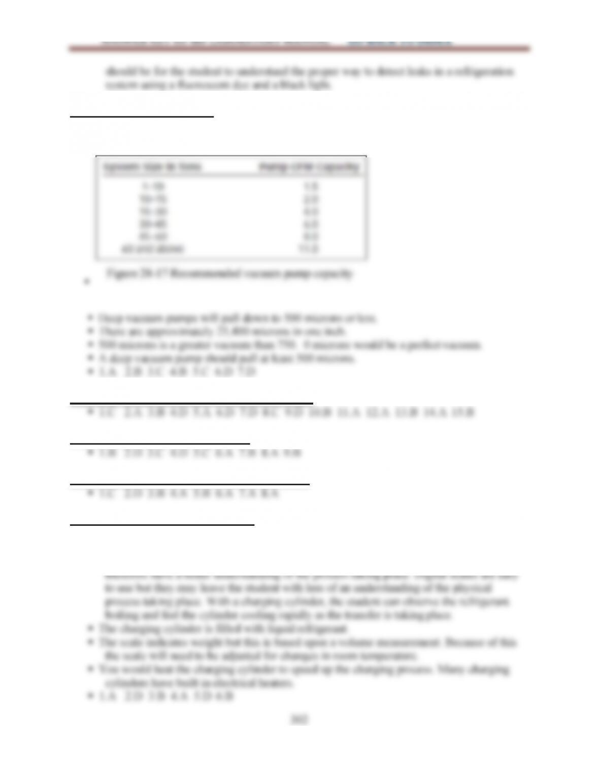
LAB 28.1 VACUUM PUMP
The answers for this lab will vary depending on the vacuum pump type.
Typical vacuum pump capacities are provide in Figure 28-17 of the Fundamentals of
LAB 28.2 DEEP METHOD OF EVACUATION
LAB 28.3 TRIPLE EVACUATION
LAB 28.4 VACUUM PRESSURE DROP TEST
LAB 29.1 CHARGING CYLINDER
Many Instructors do not use charging cylinders because they are not often used in the field
today due to the advent of easy to use digital scales. However for a lab exercise, there are
advantages of using a charging cylinder. Students can “see” the refrigerant and may
303
ANSWER KEY for the LABORATORY MANUAL GO BACK TO INDEX
LAB 29.2 VAPOR CHARGING WITH CHARGING CYLINDER
Many Instructors do not use charging cylinders because they are not often used in the field
today due to the advent of easy to use digital scales. However for a lab exercise, there are
LAB 29.3 VAPOR CHARGING WITH DIGITAL SCALE
LAB 29.4 VAPOR CHARGING PARTIAL CHARGE
LAB 29.6 LIQUID CHARGING WITH COMPRESSOR RUNNING
LAB 29.7 LIQUID CHARGING WITH BLENDS (ZEOTROPES
LAB 29.8 CHARGING BY WEIGHT PACKAGED UNIT
LAB 29.9 CHARGING BY WEIGHT SPLIT SYSTEM
LAB 29.10 PRESSURE-TEMPERATURE METHOD
LAB 29.11 VAPOR CHARGE-PRESSURE/TEMPERATURE
LAB 29.12 SUPERHEAT CHARGING
304
LAB 29.13 VAPOR CHARGE-SUPERHEAT
LAB 29.14 SUBCOOLING METHOD
LAB 29.15 MANUFACTURER’S CHARGING CHART
LAB 29.16 CHECKING CHARGE ON WATER COOLED SYSTEM
LAB 30.1 USING NON-CONTACT VOLTAGE DETECTORS
LAB 30.2 ELECTRICAL SAFETY PROCEDURES
LAB 30.3 CHANGING FUSES
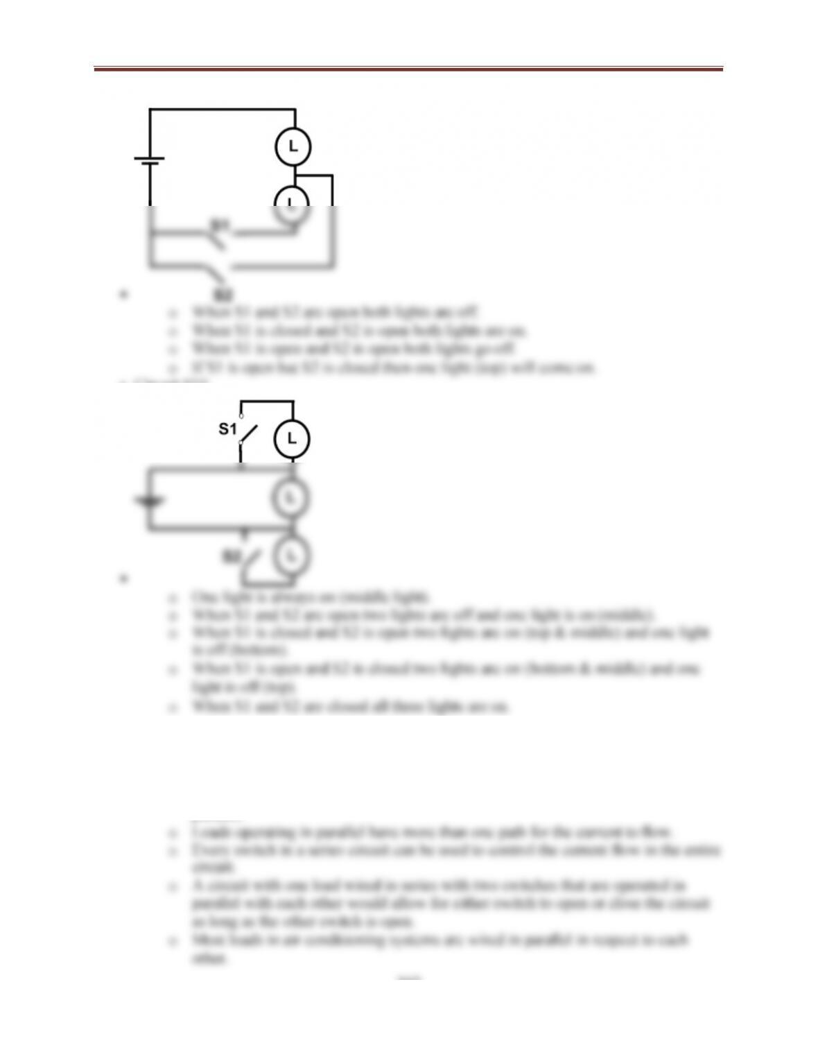
LAB 31.1 SERIES AND PARALLEL CIRCUITS
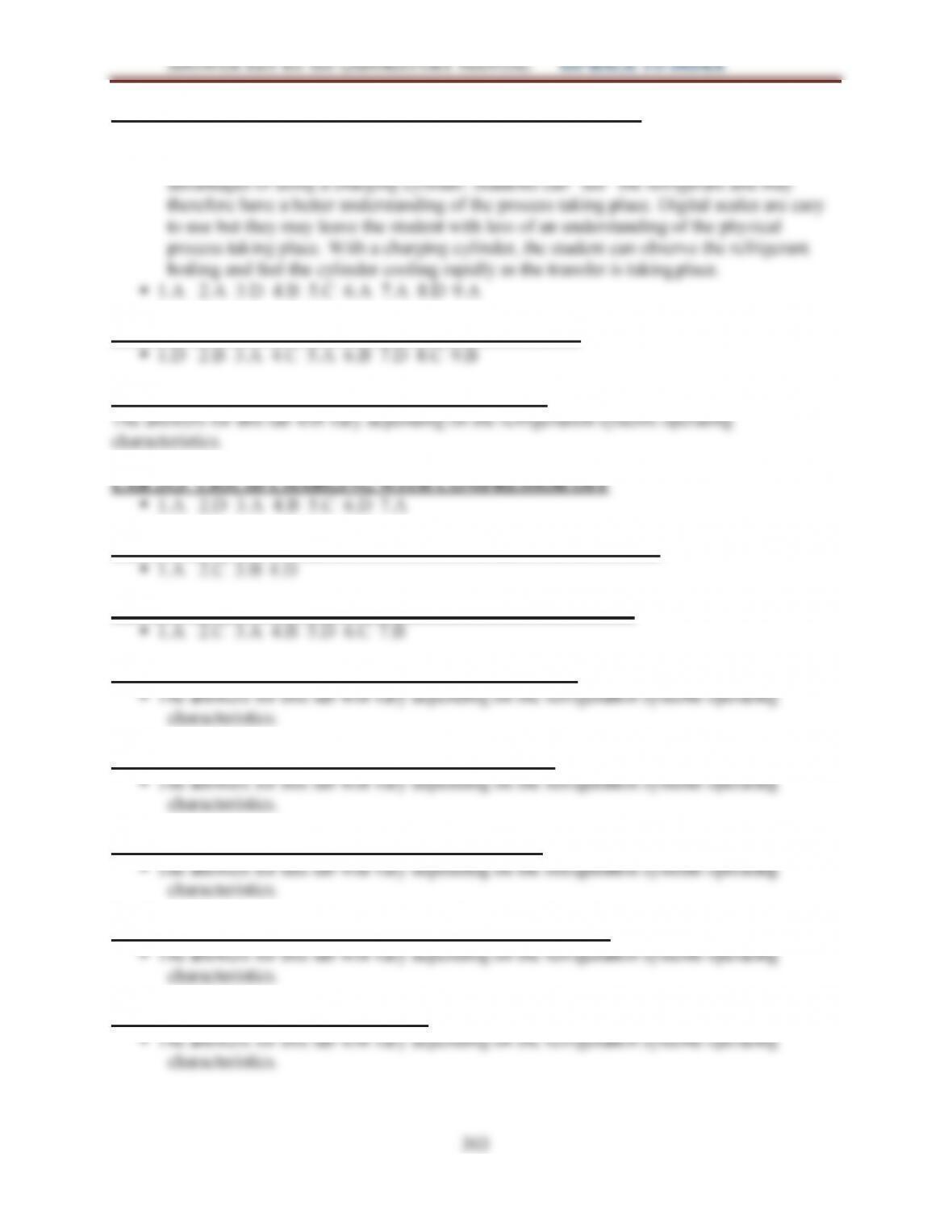
Assume you are using lights for loads.
Circuit #1
305
ANSWER KEY for the LABORATORY MANUAL GO BACK TO INDEX
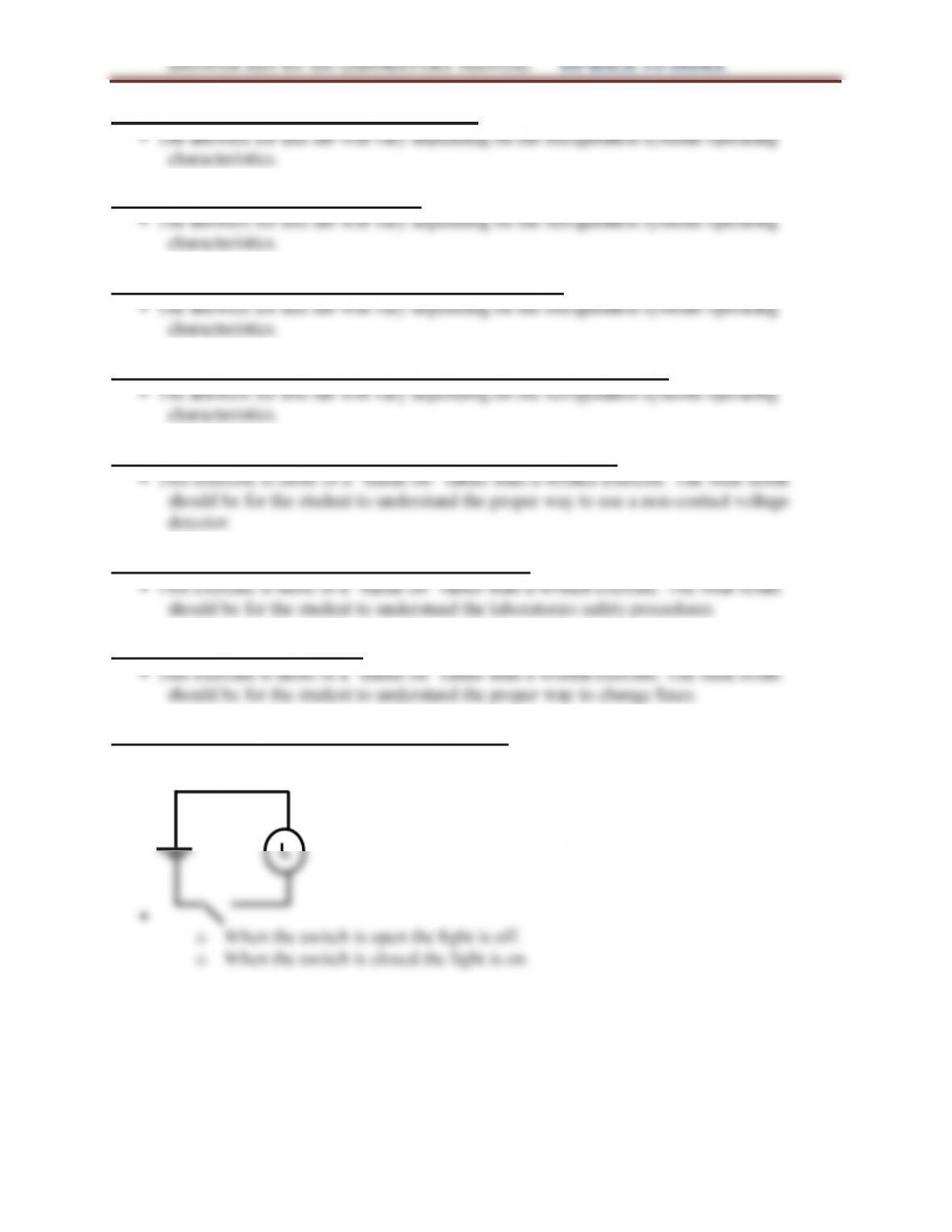
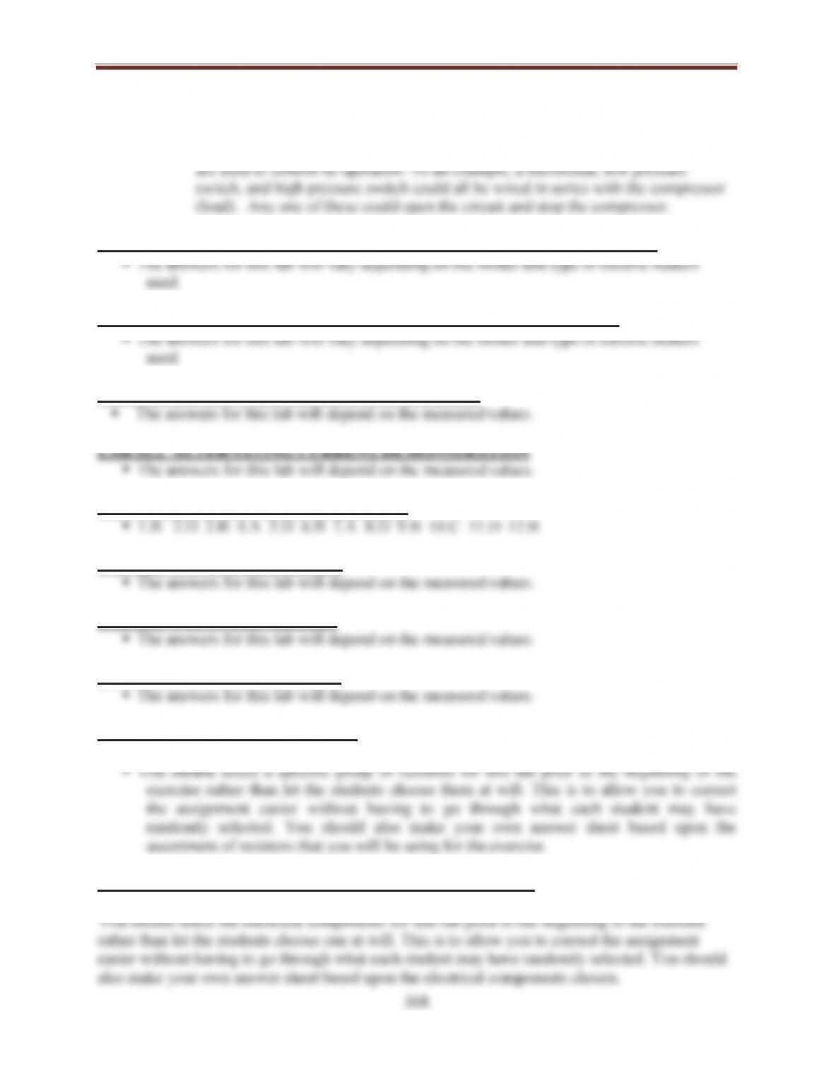
Circuit #2
Circuit #3
Circuit #4
Circuit #5
306
ANSWER KEY for the LABORATORY MANUAL GO BACK TO INDEX
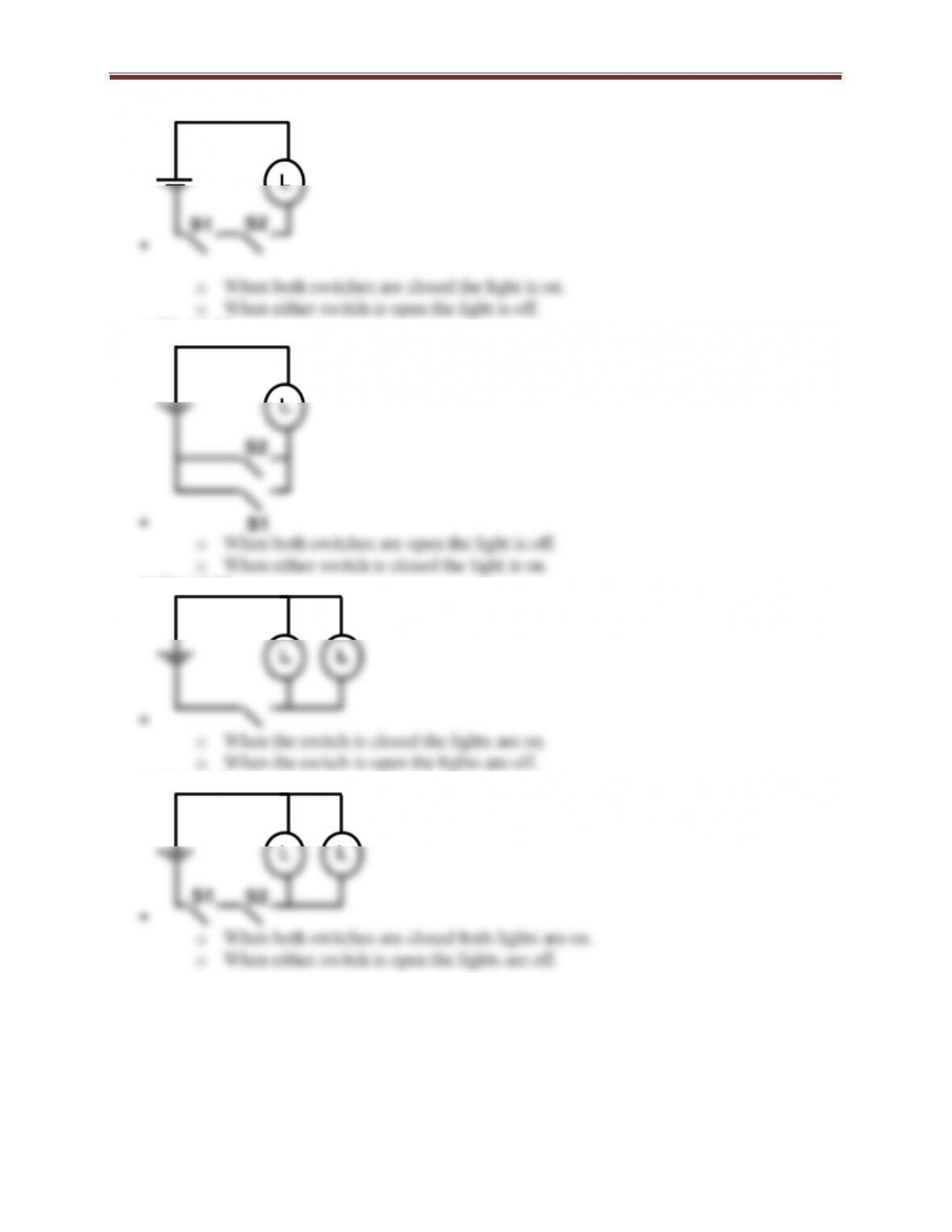
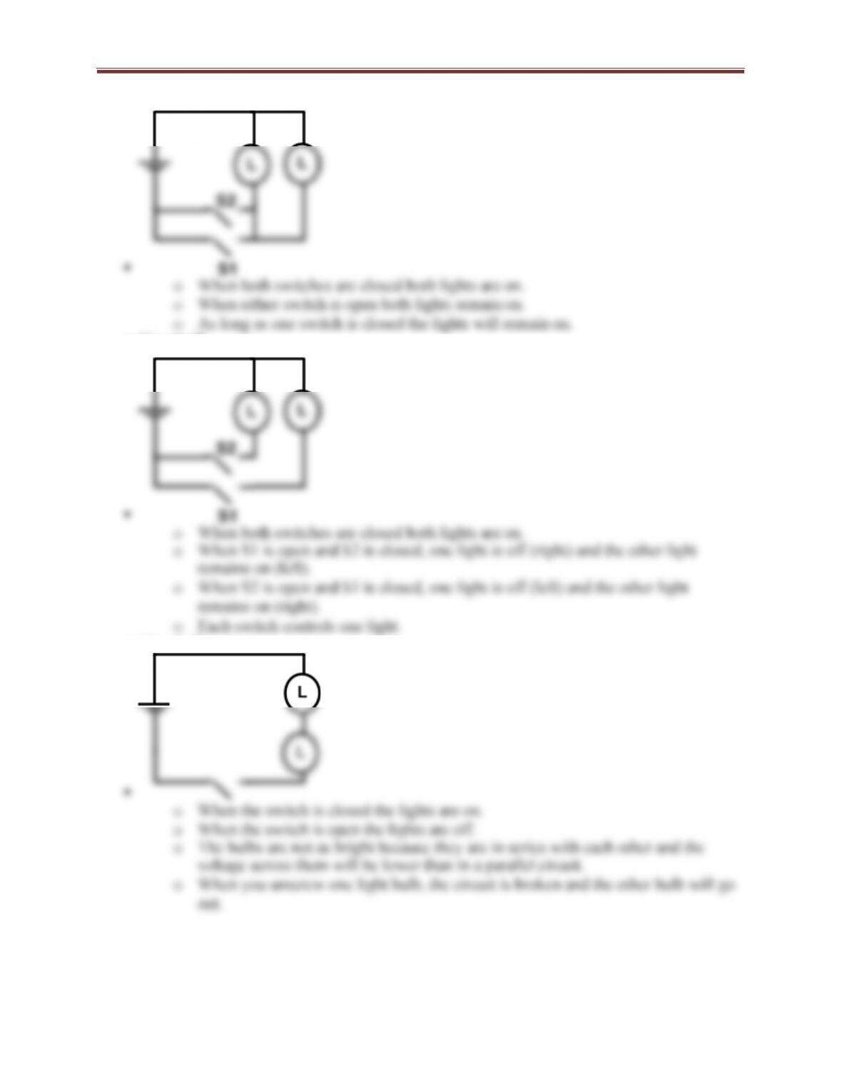
Circuit #6
Circuit #7
Circuit #8
307
ANSWER KEY for the LABORATORY MANUAL GO BACK TO INDEX
Circuit #9
Circuit #10
Summary
oA switch in series affects everything in the circuit.
oA switch in parallel can be used to control a single load.
oLoads operating in series will have greater voltage drops than loads operating in
parallel.
ANSWER KEY for the LABORATORY MANUAL GO BACK TO INDEX
oMost switches in air conditioning systems are wired in series with respect to the
load.
oSwitches in an air conditioning can be wired in series with respect to each other
for control and safety. The switches placed in series with the compressor motor
LAB 31.2 APPLY OHMS LAW TO SERIES CIRCUIT VOLTAGE CHANGES
LAB 31.3 OHMS LAW & PARALLEL CIRCUIT VOLTAGECHANGES
LAB 32.1 ALTERNATING CURRENT PRINCIPLES
LAB 33.1 ELECTRICAL MULTIMETERS
LAB 33.2 USING VOLTMETERS
LAB 33.3 USING AMP METERS
LAB 33.4 USING OHM METERS
LAB 33.5 CHECKING RESISTORS
The results for this lab will vary depending on the assortment of resistors selected.
LAB 34.1 ELECTRICAL COMPONENT IDENTIFICATION
The results for this lab will vary depending on the electrical components selected.
309
ANSWER KEY for the LABORATORY MANUAL GO BACK TO INDEX
LAB 34.2 EXAMINING LOW VOLTAGE THERMOSTATS
The results for this lab will vary depending on the types of low voltage thermostats
LAB 34.3 EXAMINING LINE VOLTAGE THERMOSTATS
The results for this lab will vary depending on the types of line voltage thermostats
LAB 34.4 IDENTIFY PRESSURE SWITCHES
The results for this lab will vary depending on the types of pressure switches selected.
LAB 34.5 IDENTIFICATION OF RELAY & CONTACTOR PARTS
The results for this lab will vary depending on the type of relay and contactor
LAB 34.6 IDENTIFYING OVERLOADS
The results for this lab will vary depending on the assortment of overloads selected.
310
ANSWER KEY for the LABORATORY MANUAL GO BACK TO INDEX
LAB 35.1 IDENTIFYING START AND RUN CAPACITORS
The results for this lab will vary depending on the assortment of capacitors selected.
LAB 35.2 EXAMINE SHADED POLE MOTOR
LAB 35.3 EXAMINE OPEN SPLIT PHASE MOTOR
LAB 35.4 EXAMINE OPEN CAPACITOR START MOTOR
LAB 35.5 EXAMINE PERMANENT SPLIT CAPACITOR (PSC) MOTOR
LAB 35.6 EXAMINE ECM MOTOR
LAB 35.7 TYPES OF ELECTRIC MOTORS
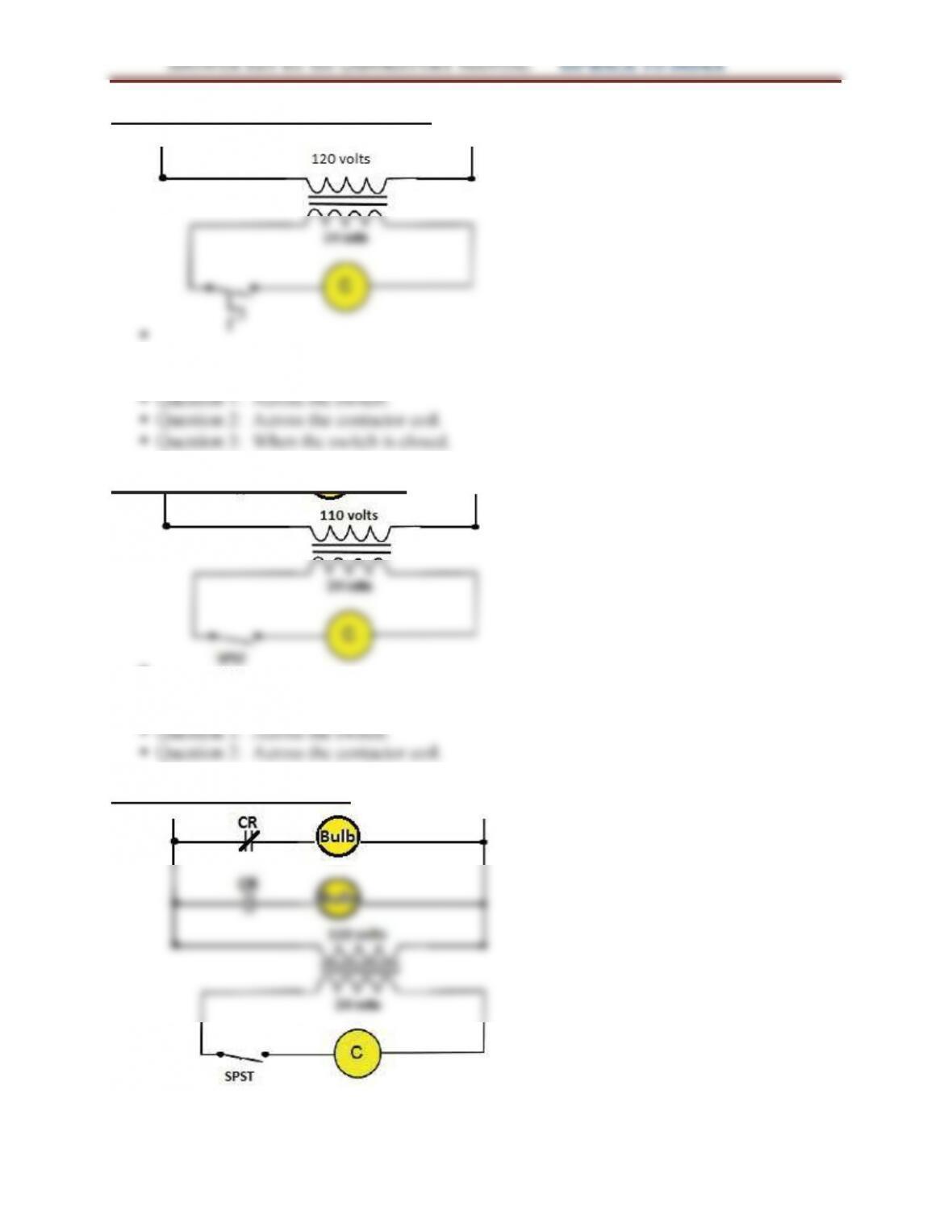
LAB 36.1 DESIGN AND OPERATE A SIMPLE 120-VOLT RELAY CIRCUIT
LAB 36.2 DESIGN AND OPERATE A SIMPLE 24-VOLT RELAY CIRCUIT
LAB 36.3 DESIGN AND OPERATE A SIMPLE 24-VOLT CONTACTOR CIRCUIT
LAB 36.4 TROUBLESHOOTING THERMAL OVERLOADS
LAB 36.5 PILOT DUTY OVERLOAD OPERATION
LAB 36.6 MAGNETIC STARTER FAMILIARIZATION
The results for this lab will vary depending on the magnetic starter disassembled.
311
LAB 36.7 WIRING MAGNETIC STARTER WITH A TOGGLE SWITCH
LAB 36.8 WIRING MAGNETIC STARTER WITH A START-STOP SWITCH
LAB 37.1 TESTING A CAPACITOR
LAB 37.2 CHECKING START AND RUN CAPACITORS USING MULTIMETER
The results for this lab will vary depending on the assortment of capacitors selected.
LAB 37.3 TESTING WINDINGS ON A SINGLE PHASE MOTOR
LAB 37.4 MOTOR INSULATION TESTING
LAB 37.5 WIRE AND OPERATE SHADED POLE MOTORS
LAB 37.6 TROUBLESHOOTING SHADED POLE MOTORS
LAB 37.7 WIRE AND OPERATE OPEN SPLIT PHASE AND CAPACITOR START
MOTORS
LAB 37.8 TROUBLESHOOTING OPEN SPLIT PHASE & CAPACITOR START
MOTORS
312
ANSWER KEY for the LABORATORY MANUAL GO BACK TO INDEX
LAB 37.9 WIRE AND OPERATE OPEN PSC MOTORS
LAB 37.10 TROUBLESHOOTING OPEN PSC MOTORS
The answers for this lab will vary depending on the measured results.
LAB 37.11 OHMING THREE PHASE MOTORS
LAB 37.12 WIRE AND OPERATE THREE PHASE MOTORS
LAB 37.14 CHECK ECM MOTOR USING TECMATE
This exercise is more of a “hands on” rather than a written exercise.
LAB 37.16 TROUBLESHOOTING CSR MOTORS
LAB 37.17 TROUBLESHOOTING MOTORS
LAB 38.1 IDENTIFY ELECTRIC COMPONENT SYMBOLS
The results for this lab will vary depending on the types of electrical components selected.
LAB 38.2 IDENTIFY COMPONENTS ON AIR CONDITIONING DIAGRAM
LAB 38.3 IDENTIFY COMPONENTS ON HEAT PUMP DIAGRAM
313
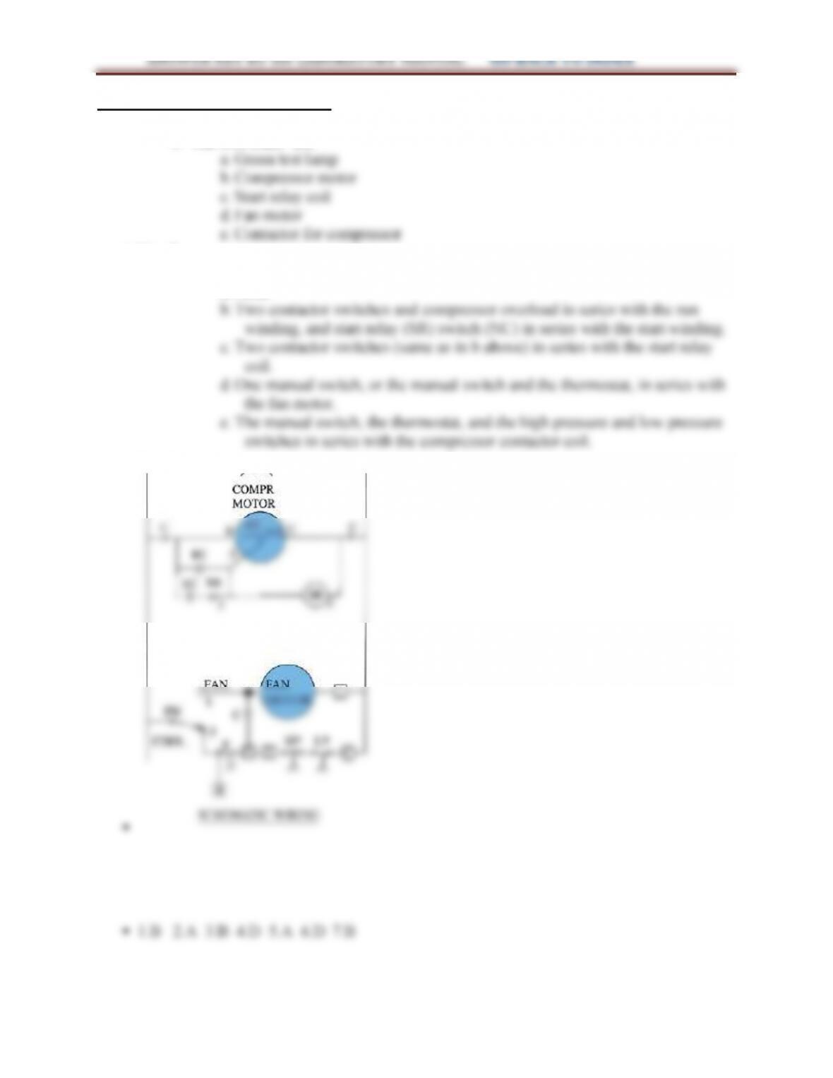
LAB 38.4 WIRING DIAGRAMS
Step 1:
oThe five loads are:
Step 2:
oLocate the switches in each circuit:
a. None
Step 3:
314
LAB 38.5 WIRING TRANSFORMERS
LAB 38.6 WIRING CONTACTORS
LAB 38.7 WIRING RELAYS