315
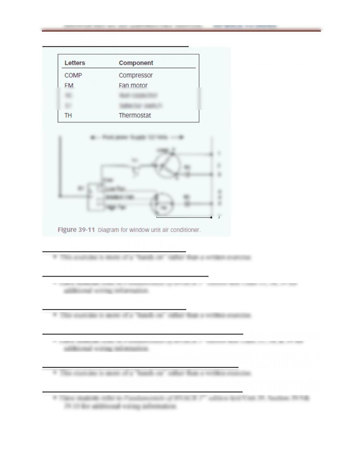
LAB 39.1 DRAW WINDOW UNIT DIAGRAM
LAB 39.2 WIRE WINDOW UNIT DIAGRAM
LAB 39.3 DRAW PACKAGED AC UNIT DIAGRAM
LAB 39.4 WIRE PACKAGED AC DIAGRAM
LAB 39.5 DRAW 2 STAGE HEAT, 2 STAGE COOL DIAGRAM
LAB 39.6 WIRE 2 STAGE HEAT 2 STAGE COOL DIAGRAM
LAB 39.7 WIRE A HEATING AND COOLING THERMOSTAT
316
LAB 39.8 WIRE A PACKAGED HEAT PUMP THERMOSTAT
Have students refer to Fundamentals of HVACR 3rd edition text Unit 39, Section 39.9&
LAB 39.9 WIRING A RELAY CONTROL SYSTEM
LAB 39.10 WIRING ANTI-SHORT CYCLE TIME DELAYS
LAB 39.11 WIRING AIR CONDITIONING CONTROL SYSTEM
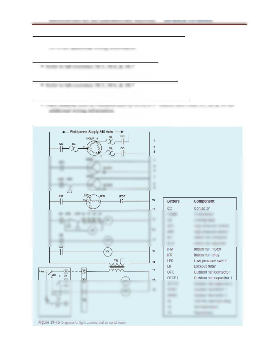
LAB 39.12 WIRING COMMERCIAL PACKAGED UNIT
317
ANSWER KEY for the LABORATORY MANUAL GO BACK TO INDEX
LAB 39.13 WIRING TWO STAGE AIR CONDITIONING SYSTEM
LAB 40.1 INSTALLING A COMMUNICATING THERMOSTAT
LAB 40.2 ACCESS COMMUNICATING THERMOSTAT SERVICE SCREENS
LAB 41.1 TESTING TRANSFORMERS
LAB 41.2 CHECKING LOW VOLTAGE THRMOSTATS
LAB 41.3 CHECKING RELAYS AND CONTACTORS
LAB 41.4 SETTING LOW PRESSURE CUTOUT
LAB 41.5 SETTING THE LOW PRESSURE CUT-OUT
LAB 41.6 SETTING HIGH PRESSURE CUTOUTS
The answers for this lab will depend on the measured values.
LAB 41.8. SETTING A BOX THERMOSTAT CONTROL
LAB 41.9 TROUBLE SHOOTING SCENARIO 1
LAB 41.10 TROUBLE SHOOTING SCENARIO 2
LAB 41.11 TROUBLE SHOOTING SCENARIO 3
318
ANSWER KEY for the LABORATORY MANUAL GO BACK TO INDEX
LAB 41.12 TROUBLE SHOOTING SCENARIO 4
LAB 42.1 USING SLING PSYCHROMETER
LAB 42.2 USING ELECTRONIC HYGROMETER (DIGITAL PSYCHROMETER)
LAB 43.1 CHANGING PANEL FILTERS
LAB 43.3 ELECTRONIC AIR CLEANERS
LAB 44.2 DEHUMIDIFIER OPERATION
This exercise is more of a “hands on” rather than a written exercise.
LAB 45.2 AIR CONDITIONING SYSTEM OPERATION
This exercise is more of a “hands on” rather than a written exercise.
LAB 46.2 WIRING A MINI-SPLIT SYSTEM
This exercise is more of a “hands on” rather than a written exercise.
LAB 47.1 WIRE DISCONNECT SWITCH AND POWER SUPPLY
LAB 47.2 WIRING A PACKAGED UNIT CONTROLS

319
ANSWER KEY for the LABORATORY MANUAL GO BACK TO INDEX
LAB 47.3 WIRING A SPLIT SYSTEM
This exercise is more of a “hands on” rather than a written exercise.
LAB 48.1 DUCT COMPONENTS
LAB 49.1 BASIC REFRIGERATION SYSTEM STARTUP
The expected suction and discharge pressures for the systems depend on the evaporator
temperature and whether the condenser is air cooled or water cooled.
LAB 49.3 TROUBLESHOOTING SCENARIO 2
This exercise is more of a “hands on” rather than a written exercise.
LAB 49.4 TROUBLESHOOTING SCENARIO 3
320
ANSWER KEY for the LABORATORY MANUAL GO BACK TO INDEX
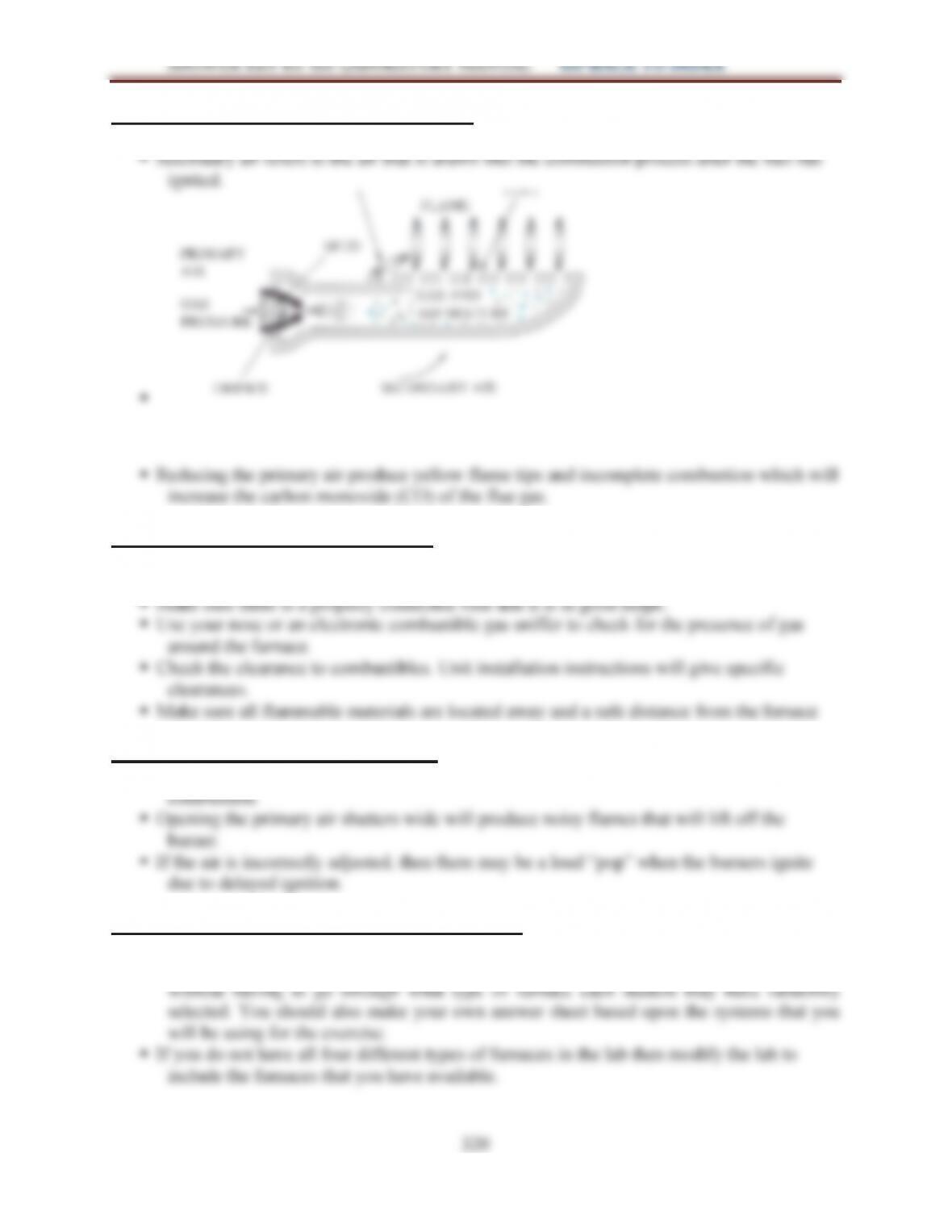
LAB 50.1 PRINCIPLES OF COMBUSTION
Primary air refers to the air that is mixed with the fuel before the air is ignited.
LAB 50.2 GAS SAFETY INSPECTION
Incomplete combustion produces carbon monoxide (CO), an odorless, tasteless, and
poisonous gas.
LAB 50.3 SERVICING GAS BURNERS
Closing the primary air shutter will produce lazy yellow flames due to incomplete
LAB 51.1 GAS FURNACE CHARACTERISITICS
You should select specific furnaces for this lab prior to the beginning of the exercise rather
than let the students choose at will. This is to allow you to correct the assignment easier
321
ANSWER KEY for the LABORATORY MANUAL GO BACK TO INDEX
LAB 51.2 NATURAL DRAFT FURNACE COMPONENTS
LAB 51.3 NATURAL DRAFT FURNACE SEQUENCE OF OPERATION
The combination gas valve pressure regulator controls the pressure.
LAB 51.4 INDUCED DRAFT FURNACE COMPONENTS
This exercise is more of a “show me” rather than a written exercise.
LAB 52.1 INSTALL REPLACEMENT THERMOSTAT
LAB 52.2 PROGRAM THERMOSTAT
LAB 52.3 PILOT TURNDOWN TEST – THERMOCOUPLE TYPE
LAB 52.4 PILOT TURNDOWN TEST – FLAME ROD TYPE
LAB 52.5 PILOT TURNDOWN TEST – FLAME IGNITOR TYPE
LAB 52.6 SEPARATE PILOT GAS REGULATOR
LAB 52.7 CHECK/TEST/REPLACE HOT SURFACE IGNITER
LAB 52.8 NATURAL DRAFT FURNACE ELECTRICAL COMPONENTS
LAB 52.9 INDUCED DRAFT ELECTRICAL COMPONENTS
322
ANSWER KEY for the LABORATORY MANUAL GO BACK TO INDEX
LAB 52.10 INDUCED DRAFT FURNACE SEQUENCE OF OPERATION
The draft inducer fan is energized first to pre-purge the vent.
LAB 52.11 WIRE A NATURAL DRAFT FURNACE
LAB 52.12 WIRE AN INDUCED DRAFT GAS FURNACE
LAB 52.13 GAS VALVE INSPECTION
You should select specific gas valves for this lab prior to the beginning of the exercise
LAB 52.14 ADJUSTING GAS REGULATORS
LAB 52.15 TESTING STANDING PILOT SAFETY DEVICES
LAB 52.16 CHECKING INTERMITTENT PILOT IGNITION SYSTEMS
With the draft switch disconnected, the burners will not light because the ignition system
does not sense a pre-purge condition which is required before the burners will light.
323
ANSWER KEY for the LABORATORY MANUAL GO BACK TO INDEX
LAB 52.17 DIRECT SPARK IGNITION CONTROLS
First the draft inducer fan is energized. It runs for 30-45 seconds to perform a pre-purge to
vent any accumulated gas or combustion products. After the pre-purge the spark igniter
LAB 53.1 GAS FURNACE STARTUP
LAB 53.2 MEASURE GAS USAGE
LAB 53.3 GAS FURNACE COMBUSTION TESTING
This exercise is “hands on” and the readings taken will vary.
LAB 53.5 CHECKING GAS PRESSURE
This exercise is “hands on” and the readings taken will vary.
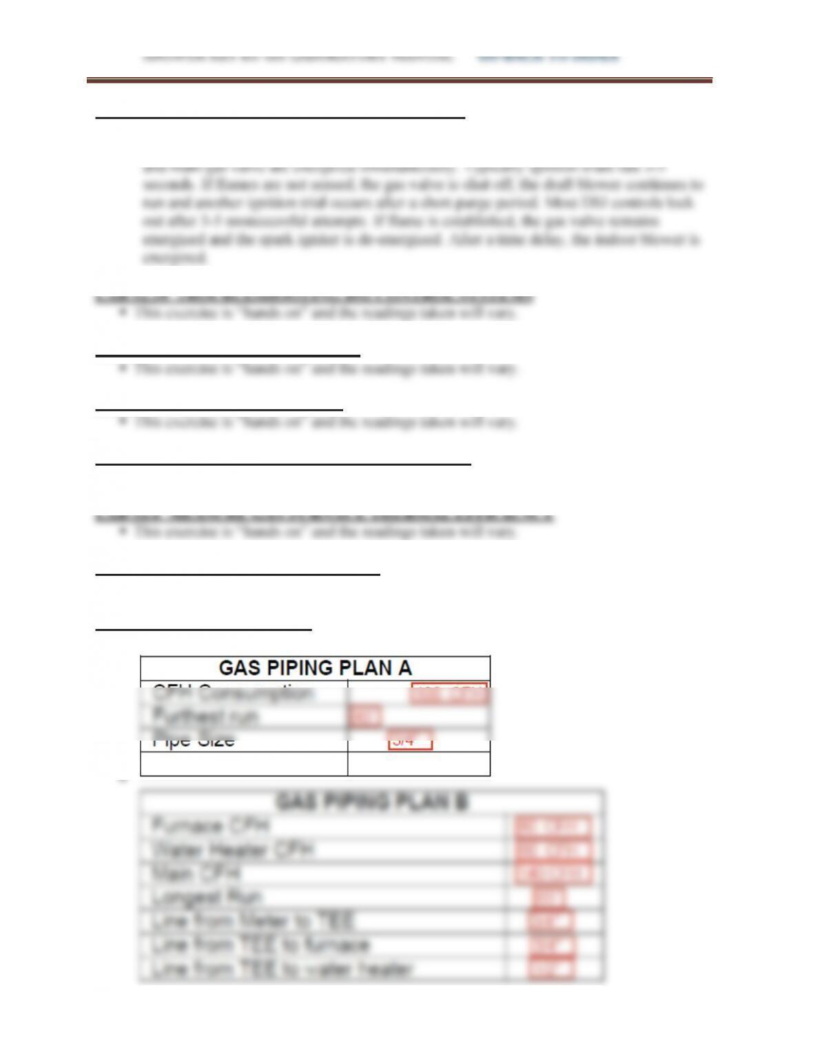
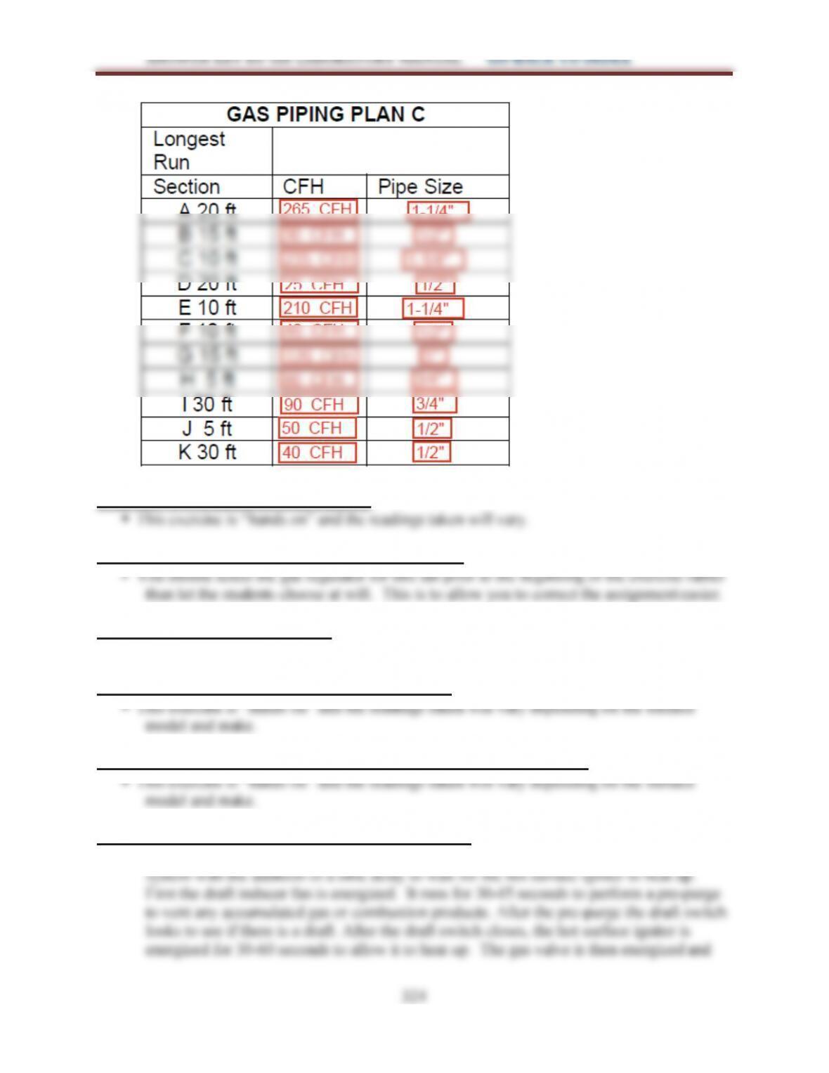
LAB 53.6 SIZING GAS LINES
324
ANSWER KEY for the LABORATORY MANUAL GO BACK TO INDEX
LAB 53.7 INSTALLING GAS PIPING
LAB 53.8 GAS INSPECTING GAS REGULATORS
LAB 53.9 MEASURING DRAFT
This exercise is “hands on” and the readings taken will vary.
LAB 53.10 MEASURING TEMPERATURE RISE
LAB 54.1 GAS FURNACE PREVENTATIVE MAINTENANCE (PM)
LAB 54.2 HOT SURFACE IGNITION OPERATION
The hot surface ignition (HSI) operating system is similar to the direct spark ignition (DSI)
ANSWER KEY for the LABORATORY MANUAL GO BACK TO INDEX
the flame sensor looks to see if the flame has been established. Typically ignition trials
last 3-5 seconds. If flames are not sensed, the gas valve is shut off, the draft blower
LAB 54.3 TROUBLESHOOTING HOT SURFACE IGNITION SYSTEMS
The results will vary depending on the furnace condition. You should troubleshoot the gas
LAB 54.4 VENT PROBLEMS
The results will vary depending on the furnace condition. You should troubleshoot the gas
LAB 54.6 GAS COMBUSTION EFFICIENCY
LAB 54.7 TROUBLESHOOTING GAS FURNACE SCENARIO 1
The results will vary depending on the furnace condition. You should troubleshoot the gas
LAB 54.9 TROUBLESHOOTING GAS FURNACE SCENARIO 3
LAB 54.11 TROUBLESHOOTING GAS FURNACE SCENARIO 5
LAB 54.13 GAS FURNACE SEASONAL START-UP AND SYSTEM CHECK
326
ANSWER KEY for the LABORATORY MANUAL GO BACK TO INDEX
LAB 56.1 OIL BURNER TUNE-UP
LAB 56.2 FINAL OIL BURNER ADJUSTMENT
LAB 56.3 OIL FURNACE PREVENTATIVE MAINTENANCE
LAB 56.4 INSTALL A REPLACEMENT FUEL OIL PUMP
LAB 57.1 OIL FIRED FURNACE STARTUP
LAB 57.2 OIL FURNACE STORAGE TANK MAINTENANCE
LAB 57.3 OIL FURNACE TWO PIPE CONVERSION
LAB 57.4 INSTALL A REPLACEMENT FUEL OIL BURNER
LAB 57.5 CHECK/TEST A CAD CELL OIL BURNER PRIMARY CONTROL
LAB 61.1 WIRING SEQUENCERS
LAB 62.1 ELECTRIC FURNACE STARTUP
LAB 62.2 CALCULATE AIRFLOW BY TEMPERATURE RISE
327
ANSWER KEY for the LABORATORY MANUAL GO BACK TO INDEX
LAB 64.1 TYPES OF HEAT PUMPS
LAB 64.2 WINDOW UNIT HEAT PUMP REFRIGERATION CYCLE
The reversing valve will reverse the flow of refrigerant so that the suction line to the
compressor becomes the discharge line and vice versa.
LAB 64.3 PACKAGED UNIT HEAT PUMP REFRIGERATION CYCLE
LAB 64.4 SPLIT SYSTEM HEAT PUMP REFRIGERATION CYCLE
LAB 64.5 REVERSING VALVE FUNDAMENTALS
LAB 64.7 HEAT PUMP ELECTRICAL COMPONENTS
This exercise is more of a “show me” rather than a written exercise.
LAB 65.2 WIRING DUAL FUEL HEAT PUMP
LAB 65.3 ELECTRIC STRIP HEAT OPERATION
328
ANSWER KEY for the LABORATORY MANUAL GO BACK TO INDEX
The electric strip heaters are normally installed after the blower.
To prevent the strips from overheating, the blower will turn on before the strips are
energized and will stay on until after the strips have de-energized.
LAB 67.1 WIRING PACKAGED HEAT PUMP
LAB 67.2 INSTALL SPLIT SYSTEM HEAT PUMP REFRIGERATION PIPING
LAB 67.3 WIRE THERMOSTAT AND CONTROL WIRING
LAB 67.4 EVACUATE AND CHARGE A SPLIT SYSTEM HEAT PUMP
LAB 67.5 HEAT PUMP START AND CHECK
329
ANSWER KEY for the LABORATORY MANUAL GO BACK TO INDEX
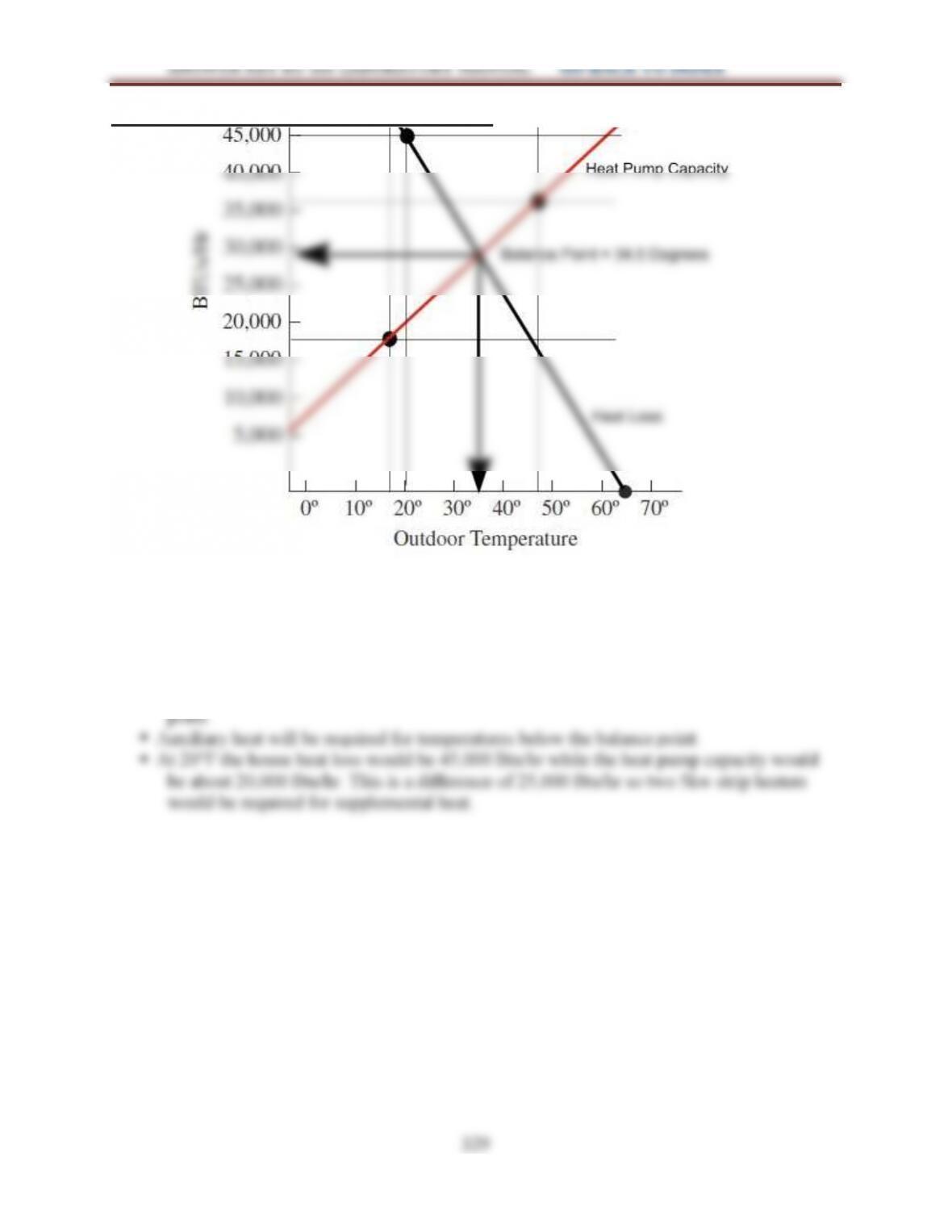
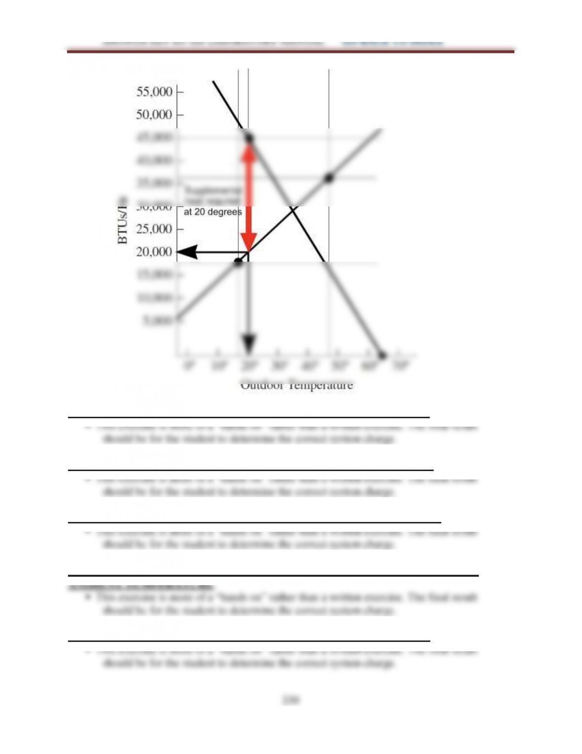
LAB 67.6 DETERMINING BALANCE POINT
The balance point temperature is approximately 34.5°F.
The system capacity and the heat load are approximately 29,500 Btu/hr at the balance
330
ANSWER KEY for the LABORATORY MANUAL GO BACK TO INDEX
LAB 68.1 PACKAGED HEAT PUMP CHARGING – COOLING CYCLE
LAB 68.2 HEAT PUMP CHARGING – COOLING CYCLE SUPERHEAT
LAB 68.3 HEAT PUMP CHARGING – COOLING CYCLE SUBCOOLING
LAB 68.4 SPLIT SYSTEM HEAT PUMP CHARING – COOLING CYCLE: COLD
LAB 68.5 PACKAGED HEAT PUMP CHARGING – HEATING CYCLE
331
ANSWER KEY for the LABORATORY MANUAL GO BACK TO INDEX
LAB 68.6 HEAT PUMP CHARGING – HEATING CYCLE DISCHARGE LINE
LAB 68.7 HEAT PUMP CHARGING – HEATING CYCLE TEMPERATURE RISE
LAB 68.8 CHECKING DEFROST CONTROLS
LAB 68.9 TROUBLESHOOTING HEAT PUMPS SCENARIO 1
The results will vary depending on the heat pump condition. You should troubleshoot the
LAB 68.10 TROUBLESHOOTING HEAT PUMPS SCENARIO 2
LAB 68.11 TROUBLESHOOTING HEAT PUMPS SCENARIO 3
LAB 68.12 HEAT PUMP SEASONAL START-UP AND SYSTEM CHECK
LAB 72.1 MANUAL J8 BLOCK LOAD
LAB 74.1 WIRING ZONE CONTROL SYSTEM
LAB 75.1 ROTATING VANE ANENOMETER
LAB 75.2 FLOW HOOD
LAB 75.3 USING MAGNEHELIC GAUGE
332
ANSWER KEY for the LABORATORY MANUAL GO BACK TO INDEX
LAB 77.1 BELT DRIVES
This exercise is “hands on” and the readings taken will vary.
LAB 77.2 DIRECT DRIVE MOTOR APPLICATIONS
LAB 77.3 INDUCTION MOTOR BLOWER PROPERTIES
Generally if the inlet to a fan is blocked, the CFM will decrease and because the fan is
LAB 77.4 ECM BLOWER PROPERTIES
LAB 82.1 WATER CIRCULATING PUMP COMPLETE SERVICE
LAB 88.1 TESTING POTENTIAL START RELAYS
LAB 88.2 OHMING SINGLE PHASE HERMETIC COMPRESSOR MOTORS
This exercise is “hands on” and the readings taken will vary.
LAB 88.3 WIRE AND OPERATE HERMETIC PSC MOTORS
LAB 88.4 TROUBLESHOOTING HERMETIC COMPRESSOR MOTORS
LAB 88.5 IDENTIFYING TYPES OF STARTING RELAYS
LAB 88.6 WIRE AND OPERATE HERMETIC SPLIT PHASE AND CAPACITOR START
COMPRESSORS
LAB 88.7 WIRE AND OPERATE CSR MOTORS
333
ANSWER KEY for the LABORATORY MANUAL GO BACK TO INDEX
LAB 88.8 INSTALL HARD START KIT
LAB 89.1 WIRE DISCONNECT SWITCH AND POWER SUPPLY
LAB 89.2 WIRING A PACKAGED UNIT
LAB 89.3 WIRING A SPLIT SYSTEM
LAB 90.1 BELT DRIVE BLOWER COMPLETE SERVICE
LAB 90.2 CLEANING COILS
LAB 90.3 TYPES OF MOTOR BEARINGS
LAB 90.4 BELT DRIVES
LAB 90.5 DIRECT DRIVE MOTOR APPLICATIONS
LAB 92.1 WATERFLOW EFFECT ON SYSTEM PERFORMANCE
Increased condenser water flow should lower system pressures andtemperatures.
Decreased condenser water flow should increase system pressures and temperatures.
LAB 92.2 EFFECT OF AIRFLOW ON SYSTEM PERFORMANCE
LAB 92.3 TROUBLESHOOTING SCENARIO 1
The results will vary depending on the system condition. You should troubleshoot
LAB 92.5 TROUBLESHOOTING SCENARIO 3