U
R GEARS APPLICATION: Food waste grinder driven by an electric motor
Problem 75 – Second pair of a double reduction drive
n
put Data: Factors in Design Analysis:
Input Power: P = 0.5 hp Alignment Factor,K
m
=1.0+C
pf
+C
ma
If F <1.0 If F>1.0 F/D
P
= 1.02
Input Speed: n
P
= 188.9 rpm Pinion Proportion Factor, C
pf
= 0.077 0.079 [0.50 < F/D
P
< 2.00]
Diametral Pitch: P
d
= 16 Enter: C
pf
= 0.079 Figure 9-12
Center Distance: C = 3.094 in Service Factor: SF = 1.00 Use 1.00 if no unusual conditions
Pitch Line Speed: v
t
= 56 ft/min
Transmitted Load: W
t
= 297 lb Reliability Factor: K
R
= 1.00 Table 9-11 Use 1.00 for R = .99
Enter: Design Life: 8000 hours See Table 9-12
Secondary Input Data: Pinion – Number of load cycles: N
P
= 9.1E+07 Guidelines: Y
N
, Z
N
Pinion: J
P
= 0.320 Fig. 9-10 Pinion: Required s
ac
= 157,454 psi See Fig. 9-19 or
Gear: J
G
= 0.415 Fig. 9-10 Gear: Required s
ac
= 152,634 psi Table 9-9
Geometry Factor: I = 0.106 Fig. 9-17 Specify materials, alloy and heat treatment, for most severe requirement.
REF: m
G
= 4.50 One possible material specification:
ted stresses: s
t
= 25219 psi Pinion Pinion: Requires HB 399: SAE 4340 OQT 800; HB 415, 12% elongation
s
t
= 19446 psi Gear Gear: Requires HB 384: SAE 4340 OQT 800; HB 415, 12% elongation
s
c
= 149581 psi Pinion Comments: Pinion and gear made from same material and heat treatment.
s
=
149581
i
G
Al f idth df i 2 Hi h t i hi h h d
G
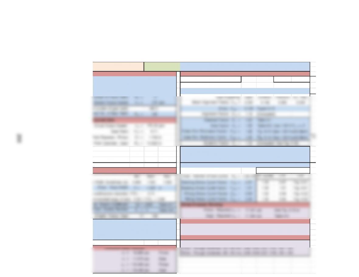
EARS APPLICATION: Small hand drill driven by an electric motor
Problem 76 – First pair of a double reduction drive
Data: Factors in Design Analysis:
Input Power: P = 0.25 hp Alignment Factor,K
m
=1.0+C
pf
+C
ma
If F <1.0 If F>1.0 F/D
P
= 0.50
Input Speed: n
P
=3000rpm Pinion Proportion Factor, C
pf
= 0.025 0.016 [0.50 < F/D
P
< 2.00]
ametral Pitch: P
d
= 24 Enter: C
pf
= 0.025 Figure 9-12
f
Pinion Teeth: N
P
=15 Type of gearing: Open Commer. Precision Ex. Prec.
O
utput Speed: n
G
= 1300 rpm Mesh Alignment Factor, C
ma
= 0.251 0.131 0.071 0.041
r
of gear teeth: 34.6 Enter: C
ma
=0.131Figure 9-13
o
f Gear Teeth: N
G
= 35 Alignment Factor: K
m
= 1.16 [Computed]
d
ata: Overload Factor: K
o
= 1.50 Table 9-1
O
utput Speed: n
G
= 1285.7 rpm Size Factor: K
s
= 1.00 Table 9–2: Use 1.00 if P
d
>= 5
Gear Ratio: m
G
= 2.33 Pinion Rim Thickness Factor: K
BP
= 1.00 Fig. 9–14: Use 1.00 if solid blank
m
eter – Pinion: D
P
=0.625 in Gear Rim Thickness Factor: K
BG
= 1.00 Fig. 9–14: Use 1.00 if solid blank
a
meter – Gear: D
G
= 1.458 in Dynamic Factor: K
v
= 1.19 [Computed: See Fig. 9-16]
nter Distance: C = 1.042 in Service Factor: SF = 1.00 Use 1.00 if no unusual conditions
c
h Line Speed: v
t
= 491 ft/min
n
smitted Load: W
t
= 17 lb Reliability Factor: K
R
= 1.00 Table 9-11 Use 1.00 for R = .99
Enter: Design Life: 5000 hours See Table 9-12
Secondary Input Data: Pinion – Number of load cycles: N
P
= 9.0E+08 Guidelines: Y
N
, Z
N
Pinion: J
P
=0.250 Fig. 9-10 Pinion: Required s
ac
= 128,205 psi See Fig. 9-19 or
Gear: J
G
=0.355 Fig. 9–10 Gear: Required s
ac
= 125,418 psi Table 9-9
o
metry Factor: I = 0.088 Fig. 9-17 Specify materials, alloy and heat treatment, for most severe requirement.
REF: m
G
= 2.33 One possible material specification:
s
tresses: s
t
= 13288 psi Pinion Pinion: Requires HB 306: SAE 4340 OQT 1100; HB 321, 19% elongation
s
t
= 9358 psi Gear Gear: Requires HB 297: SAE 4340 OQT 1100; HB 321, 19% elongation
s
c
= 115385 psi Pinion Comments: Equal reduction ratios and P
d
used for both pairs.
s
=
115385
psi
Gear
Larger face width used for second pair Same material + heat treatment used
P
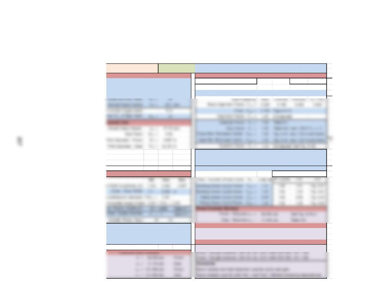
UR GEARS APPLICATION: Small hand drill driven by an electric motor
Problem 76 – Second pair of a double reduction drive
I
nput Data: Factors in Design Analysis:
Input Power: P = 0.25 hp Alignment Factor,K
m
=1.0+C
pf
+C
ma
If
F
<1.0 If
F
>1.0 F/D
P
= 0.90 <
Input Speed: n
P
= 1285.7 rpm Pinion Proportion Factor, C
pf
= 0.065 0.059 [0.50 < F/D
P
< 2.00]
Diametral Pitch: P
d
= 24 Enter: C
pf
= 0.065 Figure 9-12
O
m
ber of Pinion Teeth: N
P
=15 Type of gearing: Open Commer. Precision Ex. Prec.
s
ired Output Speed: n
G
= 550 rpm Mesh Alignment Factor, C
ma
= 0.256 0.136 0.075 0.044
u
mber of gear teeth: 35.1 Enter: C
ma
= 0.136 Figure 9-13
n
No. of Gear Teeth: N
G
= 35 Alignment Factor: K
m
= 1.20 [Computed]
p
uted data: Overload Factor: K
o
=1.50Table 9-1
Gear Ratio: m
G
= 2.33 Pinion Rim Thickness Factor: K
BP
= 1.00 Fig. 9–14: Use 1.00 if solid blank
h
Diameter – Pinion: D
P
=0.625 in Gear Rim Thickness Factor: K
BG
= 1.00 Fig. 9–14: Use 1.00 if solid blank
ch Diameter – Gear: D
G
= 1.458 in Dynamic Factor: K
v
= 1.12 [Computed: See Fig. 9-16]
Center Distance: C = 1.042 in Service Factor: SF = 1.00 Use 1.00 if no unusual conditions
0
Pitch Line Speed: v
t
= 210 ft/min
Transmitted Load: W
t
= 39 lb Reliability Factor: K
R
= 1.00 Table 9-11 Use 1.00 for R = .99
7
Enter: Design Life: 5000 hours See Table 9-12
Secondary Input Data: Pinion – Number of load cycles: N
P
= 3.9E+08 Guidelines: Y
N
, Z
N
Pinion: J
P
= 0.250 Fig. 9-10 Pinion: Required s
ac
= 126,985 psi See Fig. 9-19 or
Gear: J
G
= 0.355 Fig. 9-10 Gear: Required s
ac
= 124,283 psi Table 9-9
n
g Geometry Factor: I = 0.088 Fig. 9–17 Specify materials, alloy and heat treatment, for most severe requirement.
REF: m
G
= 2.33 One possible material specification:
p
uted stresses: s
t
= 13622 psi Pinion Pinion: Requires HB 304: SAE 4340 OQT 1100; HB 321, 19% elongation
s
t
= 9593 psi Gear Gear: Requires HB 296: SAE 4340 OQT 1100; HB 321, 19% elongation
s
c
= 116826 psi Pinion Comments: Equal reduction ratios and P
d
used for both pairs.
s
c
= 116826 psi Gear Larger face width used for second pair. Same material + heat treatment used
Stresses nearly equal in both pairs requiring equal hardnesses
263
Connect blade wheel to output shaft
Band saw driven by electric motor of gear reducer in Problem 76
Problem 77 – Produce a linear speed of blade = 375 ft/min Blade speed = perpheral speed of 9.0 in wheel
v
t
of wheel = S
D
w
n
w
/12
Input Power: P = 0.25 hp n
w
= 12v
tw
/(S
D
w
) =159.2 rpm
Input Speed: n
P
= 551 rpm From Problem 76
Diametral Pitch: P
d
= 12
Number of Pinion Teeth: N
P
= 18
Desired Output Speed: n
G
= 159.2 rpm To produce blade
Computed number of gear teeth: 62.32 speed of 375 ft/min
Enter: Chosen No. of Gear Teeth: N
G
= 62
Actual Output Speed: n
G
= 160.0 rpm
Gear Ratio: m
G
= 3.444
Tooth Form:
Lewis Form Factor: Y = 0.521 Table 9-15
Safety Factor: SF = 1.50 Ref: Table 9–1 (K
o
)
Material:
Face Width – Gear: F = 0.220 in Same as for pinion
Actual Bending Stress in Gear: s
t
= 4355 psi Must be < s
at
DESIGN OF PLASTIC SPUR GEARS
20 degree full depth
Unfilled Nylon
Application:
Initial Input Data:
Computed data:
Secondary Input Data – Pinion:
ͺǤ Ǥݒ ʹǤͲȀ ൌ ͳʹͲȀ
ͳǣ݊ൌ ͳͷͲͲǢ݊ൌ ͳʹǤ͵
ܰ
ൌ ͳǡ ܰൌ ͳͶͺǡ ܸ
ோభൌ ͺǤͳ
ǣ
ǣǡǡͳʹǤ
ʹǤͲȀǡǣ
ܦ݊
ௗܸܶൌ݊
Ȁ݊
ͳͲǤͲ ͶͷǤͺͶ ͵ʹǤʹ
265
Summary:۾ܗܟ܍ܚ ൌ Ǥ ܐܘǢࡷൌ Ǥ Ǣ ࡼࢊࢋ࢙ ൌ ૠǤ ܐܘǢ ۿܝ܉ܔܑܜܡ ൌ ࢜
Ǥ
AllgearsmadefromSAE4340:
ܲ
ௗܰ
ܰ
ܦ
ܦ
ீܨ ܥ
F
SPUR GEARS APPLICATION: Rack and pinion driven by a fluid power motor
Problem 78 – First reduction
ti
al Input Data: Factors in Design Analysis:
Input Power: P = 5 hp Alignment Factor, Km=1.0+Cpf +Cma If F<1.0 If F>1.0 F/D P = 0.71 <—
–
Input Speed: nP = 1500 rpm Pinion Proportion Factor, Cpf = 0.046 0.048 [0.50 < F/DP< 2.00]
Diametral Pitch: Pd = 10 Enter: Cpf = 0.048 Figure 9-12 Ot
h
N
umber of Pinion Teeth: NP =17 Type of gearing: Open Commer. Precision Ex. Prec.
Desired Output Speed: nG = 172 rpm Mesh Alignment Factor, Cma = 0.267 0.146 0.083 0.050
d
number of gear teeth: 148.3 Enter: Cma = 0.146 Figure 9-13
o
sen No. of Gear Teeth: NG = 148 Alignment Factor: Km = 1.19 [Computed]
o
mputed data: Overload Factor: K o = 1.50 Table 9-1
Actual Output Speed: nG = 172.30 rpm Size Factor: K s = 1.00 Table 9–2: Use 1.00 if Pd>= 5
P
itch Diameter – Pinion: DP=1.700 in Gear Rim Thickness Factor: K BG = 1.00 Fig. 9–14: Use 1.00 if solid blank F
o
Pitch Diameter – Gear: DG = 14.800 in Dynamic Factor: K v = 1.35 [Computed: See Fig. 9-16]
Center Distance: C = 8.250 in Service Factor: SF = 1.00 Use 1.00 if no unusual conditions 0.
8
Pitch Line Speed: vt = 668 ft/min
Transmitted Load: Wt = 247 lb Reliability Factor: K R = 1.00 Table 9-11 Use 1.00 for R = .99
5
Enter: Design Life: 1500 hours See Table 9-12
Secondary Input Data: Pinion – Number of load cycles: NP = 1.4E+08 Guidelines: YN, Z N
.
o
7
7
7
d
ing Geometry Factors: Stress Analysis: Pitting
Pinion: JP = 0.295 Fig. 9–10 Pinion: Required sac = 126,062 psi See Fig. 9-19 or
Gear: JG = 0.425 Fig. 9–10 Gear: Required sac = 119,695 psi Table 9-9
itting Geometry Factor: I = 0.110 Fig. 9–17 Specify materials, alloy and heat treatment, for most severe requirement.
REF: mG = 8.71 One possible material specification:
st = 16,826 psi Pinion Pinion: Through hardened, 281 HB min, SAE 4340 OQT 1100, HB = 321
st = 11,679 psi Gear
sc = 118,498 psi Pinion
sc = 118,498 psi Gear
F
SPUR GEARS APPLICATION: Rack and pinion driven by a fluid power motor
Problem 78 – Second reduction
t
ial Input Data: Factors in Design Analysis:
Input Power: P = 5 hp Alignment Factor, K m=1.0+Cpf +Cma If F<1.0 If F>1.0 F/D P = 0.94 <—
–
Input Speed: nP = 172.3 rpm Pinion Proportion Factor, Cpf = 0.069 0.088 [0.50 < F/DP< 2.00]
Diametral Pitch: Pd = 6Enter: Cpf = 0.088 Figure 9-12 Ot
h
N
umber of Pinion Teeth: NP =16 Type of gearing: Open Commer. Precision Ex. Prec.
Desired Output Speed: nG = 38.2 rpm Mesh Alignment Factor, Cma = 0.288 0.166 0.099 0.063
d number of gear teeth: 72.2 Enter: Cma =0.166Figure 9-13
o
sen No. of Gear Teeth: NG = 73 Alignment Factor: K m = 1.25 [Computed]
o
mputed data: Overload Factor: K o =1.50Table 9-1
Actual Output Speed: nG = 37.76 rpm Size Factor: K s =1.00Table 9-2: Use 1.00 if Pd>= 5
P
itch Diameter – Pinion: DP=2.667 in Gear Rim Thickness Factor: K BG = 1.00 Fig. 9-14: Use 1.00 if solid blank F
o
Pitch Diameter – Gear: DG = 12.167 in Dynamic Factor: K v = 1.15 [Computed: See Fig. 9-16]
Center Distance: C = 7.417 in Service Factor: SF = 1.00 Use 1.00 if no unusual conditions 0.
Pitch Line Speed: vt = 120 ft/min
Transmitted Load: Wt = 1372 lb Reliability Factor: K R = 1.00 Table 9-11 Use 1.00 for R = .99
5
Enter: Design Life: 1500 hours See Table 9-12
Secondary Input Data: Pinion – Number of load cycles: NP = 1.6E+07 Guidelines: YN, Z N
7
7
7
d
ing Geometry Factors: Stress Analysis: Pitting
Pinion: JP = 0.265 Fig. 9–10 Pinion: Required sac = 153,423 psi See Fig. 9-19 or
Gear: JG = 0.400 Fig. 9-10 Gear: Required sac = 147,465 psi Table 9-9
itting Geometry Factor: I = 0.102 Fig. 9–17 Specify materials, alloy and heat treatment, for most severe requirement.
REF: mG = 4.56 One possible material specification:
st = 26,858 psi Pinion Pinion: Through hardened, 368 HB min, SAE 4340 OQT 900, HB = 388
st = 17,793 psi Gear Comments:
sc = 151,889 psi Pinion Same material and heat treatment used for pinion and gear.
sc = 151,889 psi Gear Same material used for both Pair 1 and Pair2; Different tempering temperatures.
268
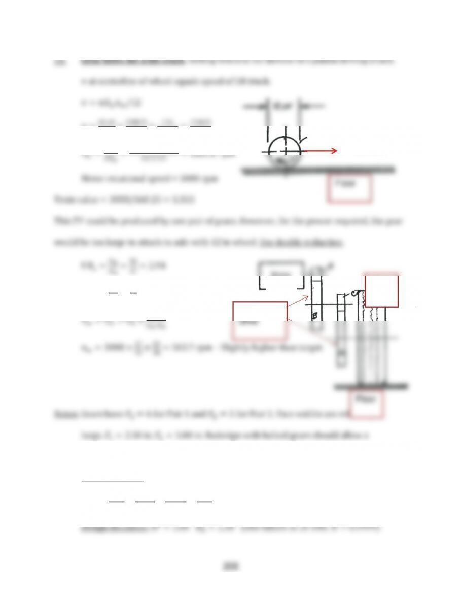
ͻǤ GeardriveforalifttruckǤǤ
ݒǤ
ݒൌߨܦ
௪݊௪Ȁͳʹ
ݒൌ
୦୰ ൈହଶ଼୲
୫୧ ൈଵ୦୰
୫୧୬ ൌଵ୲
୫୧୬
ǤǤ
ǣ
ଵ୦୰
ୢୟ୷ ൈୢୟ୷ୱ
୵୩ ൈହଶ୵୩ୱ
୷୰ ൈଶ୷୰
ଵൌ ͻͻͺͶͲ ൌ ͳͲͲͲͲͲ
Wheel
v = 20 mi/hr
R
GEARS APPLICATION: Industrial lift truck drive to wheels – Driven by a DC motor
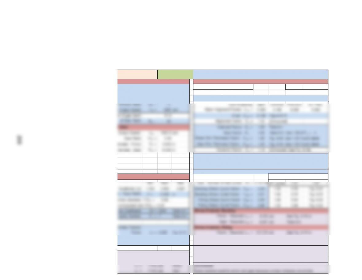
Problem 79 – First pair
u
t Data: Factors in Design Analysis:
Input Power: P = 20 hp Alignment Factor,K
m=1.0+Cpf +Cma If F <1.0 If F>1.0 F/D P = 0.88
Input Speed: nP = 3000 rpm Pinion Proportion Factor, Cpf = 0.063 0.082 [0.50 < F/DP< 2.00]
D
iametral Pitch: Pd = 6Enter: Cpf = 0.082 Figure 9-12
a
D
C
enter Distance: C = 5.583 in Service Factor: SF = 1.00 Use 1.00 if no unusual conditions
t
ch Line Speed: vt = 2225 ft/min
a
nsmitted Load: Wt = 297 lb Reliability Factor: K R = 1.50 Table 9-11 Use 1.00 for R = .99
Enter: Design Life: 100000 hours See Table 9-12
Secondary Input Data: Pinion – Number of load cycles: NP = 1.8E+10 Guidelines: YN, Z N
p
Q
Gear: JG = 0.380 Fig. 9–10 Gear: Required s ac = 124,609 psi Table 9-9
e
ometry Factor: I = 0.097 Fig. 9–17 Specify materials, alloy and heat treatment, for most severe requirement.
REF: mG = 2.94 One possible material specification:
d
stresses: st = 5430 psi Pinion Pinion: Requires HB 306: SAE 4340 OQT 1100; HB 321, 19% elongation
st = 4187 psi Gear Gear: Requires HB 297: SAE 4340 OQT 1100; HB 321, 19% elongation
sc = 71442 psi Pinion Comments:
sc = 71442 psi Gear Same material used for pinion and gear because contact stresses are similar.
[Problems80to83aresingleǦreductiongearpairsmadefromplasticgears.]
R
GEARS APPLICATION: Industrial lift truck drive to wheels – Driven by a DC motor
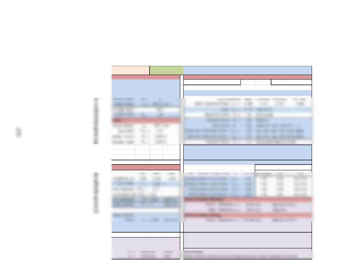
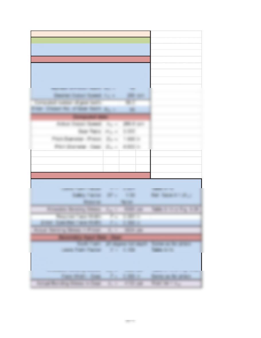
Problem 79 – Second pair
u
t Data: Factors in Design Analysis:
Input Power: P = 20 hp Alignment Factor,K
m=1.0+Cpf +Cma If F <1.0 If F>1.0 F/D P = 0.71
Input Speed: nP = 1020 rpm Pinion Proportion Factor, Cpf = 0.046 0.071 [0.50 < F/DP< 2.00]
D
iametral Pitch: Pd = 5Enter: Cpf = 0.071 Figure 9-12
a
D
C
enter Distance: C = 5.900 in Service Factor: SF = 1.00 Use 1.00 if no unusual conditions
t
ch Line Speed: vt = 1122 ft/min
a
nsmitted Load: Wt = 588 lb Reliability Factor: K R = 1.50 Table 9-11 Use 1.00 for R = .99
Enter: Design Life: 100000 hours See Table 9-12
Secondary Input Data: Pinion – Number of load cycles: NP = 6.1E+09 Guidelines: YN, Z N
p
Q
Gear: JG = 0.380 Fig. 9–10 Gear: Required s ac = 130,475 psi Table 9-9
e
ometry Factor: I = 0.092 Fig. 9–17 Specify materials, alloy and heat treatment, for most severe requirement.
REF: mG = 1.81 One possible material specification:
d
stresses: st = 6338 psi Pinion Pinion: Requires HB 320: SAE 4340 OQT 1100; HB 321, 19% elongation
st = 5504 psi Gear Gear: Requires HB 315: SAE 4340 OQT 1100; HB 321, 19% elongation
sc = 75676 psi Pinion Comments:
sc = 75676 psi Gear Same material used for pinion and gear because contact stresses are similar.
271
Small band saw driven by an electric motor
Problem 80 – One possible design
Input Power: P = 0.5 hp
Input Speed: n
P
= 860 rpm
Diametral Pitch: P
d
= 12
Center Distance: C = 6.333 in
Pitch Line Speed: v
t
= 337.7 ft/min
Transmitted Load: W
t
= 48.84 lb
Tooth Form:
Safety Factor: SF = 1.50 Same as for pinion
Material:
Face Width – Gear: F = 0.300 in Same as for pinion
Actual Bending Stress in Gear: s
t
= 4133 psi Must be < s
at
Acetal
DESIGN OF PLASTIC SPUR GEARS
Application:
Initial Input Data:
Secondary Input Data – Pinion:
20 degree full depth
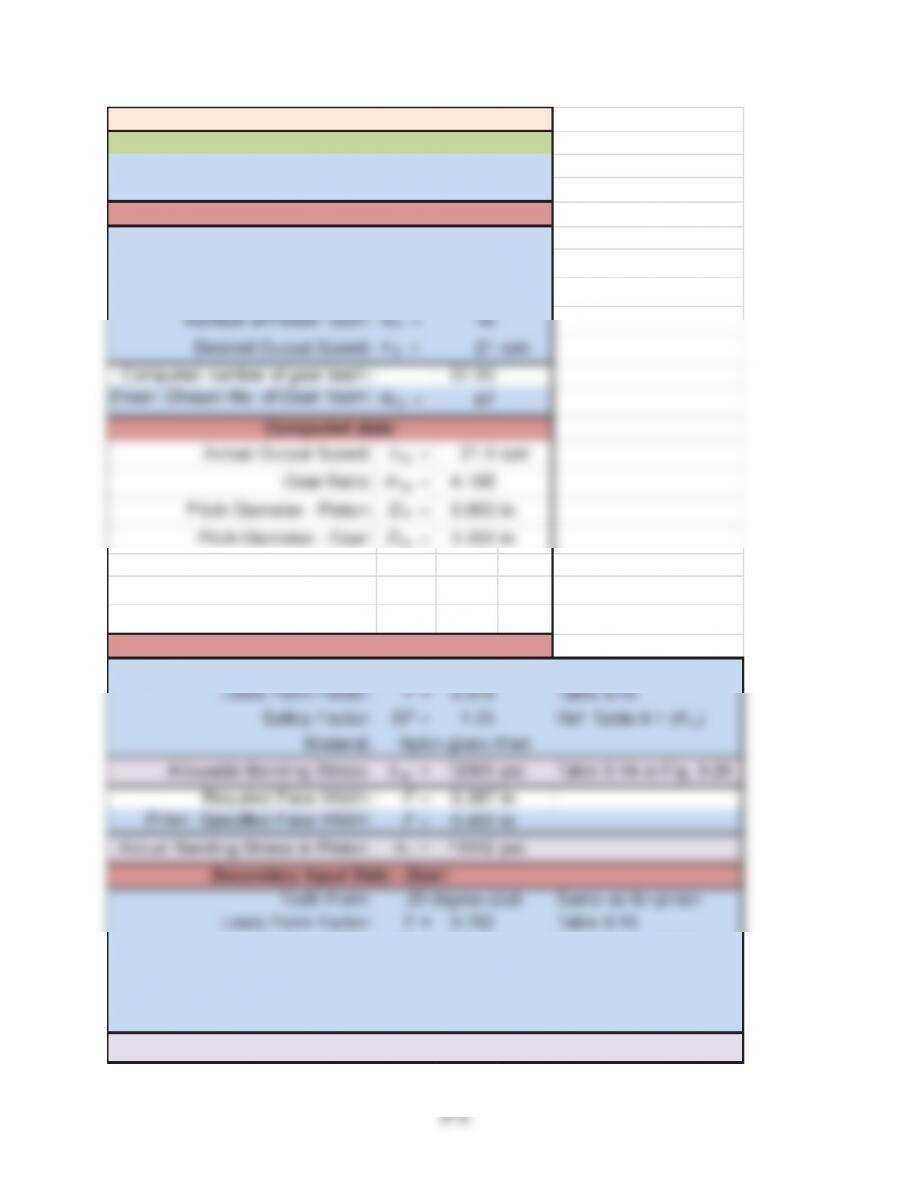
Paper feed roll driven by an electric motor
Problem 81 – One possible design
Input Power: P = 0.06 hp
Input Speed: n
P
= 88 rpm
Diametral Pitch: P
d
= 20
Center Distance: C = 4.150 in
Pitch Line Speed: v
t
= 18.4 ft/min
Transmitted Load: W
t
= 107.4 lb
Tooth Form:
Safety Factor: SF = 1.25 Same as for pinion
Material:
Allowable Bending Stress: s
at
= 12000 psi Table 9-14 or Fig. 9-26
Face Width – Gear: F = 0.400 in Same as for pinion
Actual Bending Stress in Gear: s
t
= 8583 psi Must be < s
at
Nylon-glass filled
DESIGN OF PLASTIC SPUR GEARS
Application:
Initial Input Data:
Secondary Input Data – Pinion:
20 degree stub
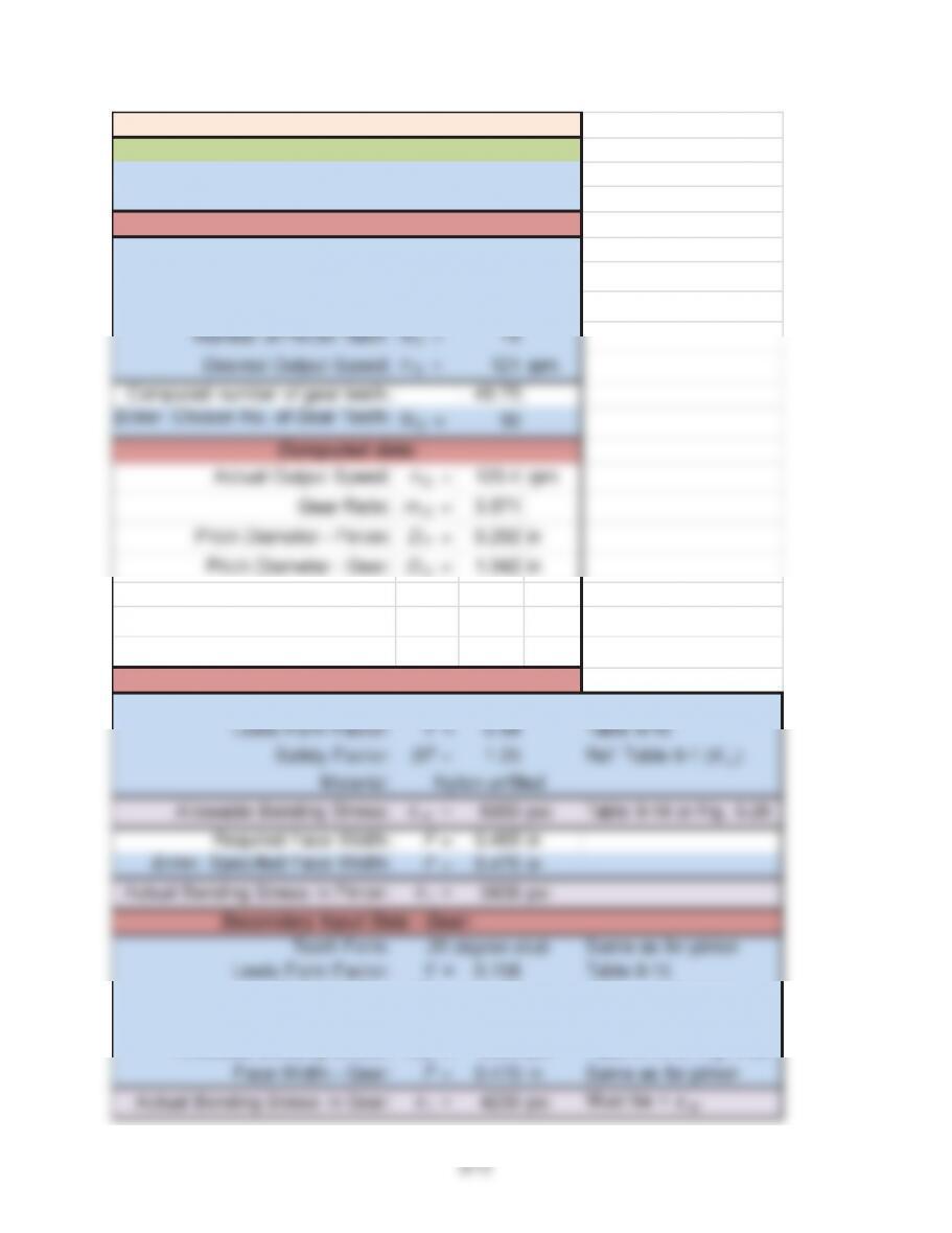
273
Wheels of remote control car-Electric motor drive
Problem 82 – One possible design
Input Power: P = 0.025 hp
Input Speed: n
P
= 430 rpm
Diametral Pitch: P
d
= 48
Center Distance: C = 1.333 in
Pitch Line Speed: v
t
= 32.8 ft/min
Transmitted Load: W
t
= 25.1 lb
Toot h Form:
Safety Factor: SF = 1.25 Same as for pinion
Material:
Allowable Bending Stress: s
at
= 6000 psi Table 9-14 or Fig. 9-26
Face Width – Gear: F = 0.470 in Same as for pinion
Actual Bending Stress in Gear: s
t
= 4230 psi Must be < s
at
Nylon-unfilled
DESIGN OF PLASTIC SPUR GEARS
Application:
Initial Input Data:
Secondary Input Data – Pinion:
20 degree stub
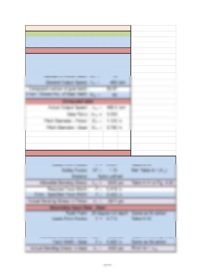
274
Food-chopping machine driven by electric motor
Problem 83 – One possible design
Input Power: P = 0.65 hp
Input Speed: n
P
= 1560 rpm
Diametral Pitch: P
d
= 16
Center Distance: C = 4.875 in
Pitch Line Speed: v
t
= 459.5 ft/min
Transmitted Load: W
t
= 46.7 lb
Tooth Form:
Safety Factor: SF = 1.75 Same as for pinion
Material:
Face Width – Gear: F = 0.420 in Same as for pinion
Actual Bending Stress in Gear: s
t
= 4363 psi Must be < s
at
Acetal–unfilled
DESIGN OF PLASTIC SPUR GEARS
Application:
Initial Input Data:
Secondary Input Data – Pinion:
20 degree full depth