CHAPTER 9
SPUR GEAR DESIGN
Forces on Spur Gear Teeth
ͳǤ ǣ߶ ൌ ʹͲιǡ ܲ ൌ Ǥͷǡ ݊ൌ ͳͷͲǡ ܰൌ ʹͲǡ ܰீൌ ʹǡ ܲௗൌͳʹ
Ǥܶ
ൌଷሺሻ
ൌଷሺǤହሻ
ଵହ ൌ ʹͲ ή
Ǥܹ
ேൌܹ
௧Ȁ ܿݏ ߶ ൌ ͵ʹͶȀ ܿݏ ʹͲι ൌ ͵Ͷͷ
ʹǦǤ
226
Problem 1 Pressure angle = 20 degrees
Chapter 9 Power = 7.5 hp
pinion speed = 1750 rpm
Given data teeth in pinion = 20
Problem 2 Pressure angle = 20 degrees
Chapter 9 Power = 50 hp
pinion speed = 1150 rpm
Given data teeth in pinion = 18
teeth in gear = 68
Forces on Spur Gear Teeth
227
Problem 3 Pressure angle = 20 degrees
Chapter 9 Power = 0.75 hp
pinion speed = 3450 rpm
Given data teeth in pinion = 24
teeth in gear = 110
diametral pitch = 24
RESULTS:
a. Gear speed = 752.7 rpm
b. VR = m
G
= 4.583
Problem 4 Pressure angle = 25 degrees
Chapter 9 Power = 7.5 hp
pinion speed = 1750 rpm
Given data teeth in pinion = 20
teeth in gear = 72
diametral pitch = 12
RESULTS:
a. Gear speed = 486.1 rpm
b. VR = m
G
= 3.600
Forces on Spur Gear Teeth
Forces on Spur Gear Teeth
228
Problem 5 Pressure angle = 25 degrees
Chapter 9 Power = 50 hp
RESULTS:
a. Gear speed = 304.4 rpm
b. VR = m
G
= 3.778
c. pinion PD = 3.600 in
Problem 6 Pressure angle = 25 degrees
RESULTS:
a. Gear speed = 752.7 rpm
b. VR = m
G
= 4.583
c. pinion PD = 1.000 in
gear PD = 4.583 in
d. center distance = C = 2.792 in
e. pitch line speed = 903 ft/min
f. torque on pinion shaft = 13.7 lb in
torque on gear shaft = 62.8 lb in
g. tangential force = 27.4 lb
h. radial force = 12.8 lb
i. normal force = 30.2 lb
Forces on Spur Gear Teeth
Forces on Spur Gear Teeth
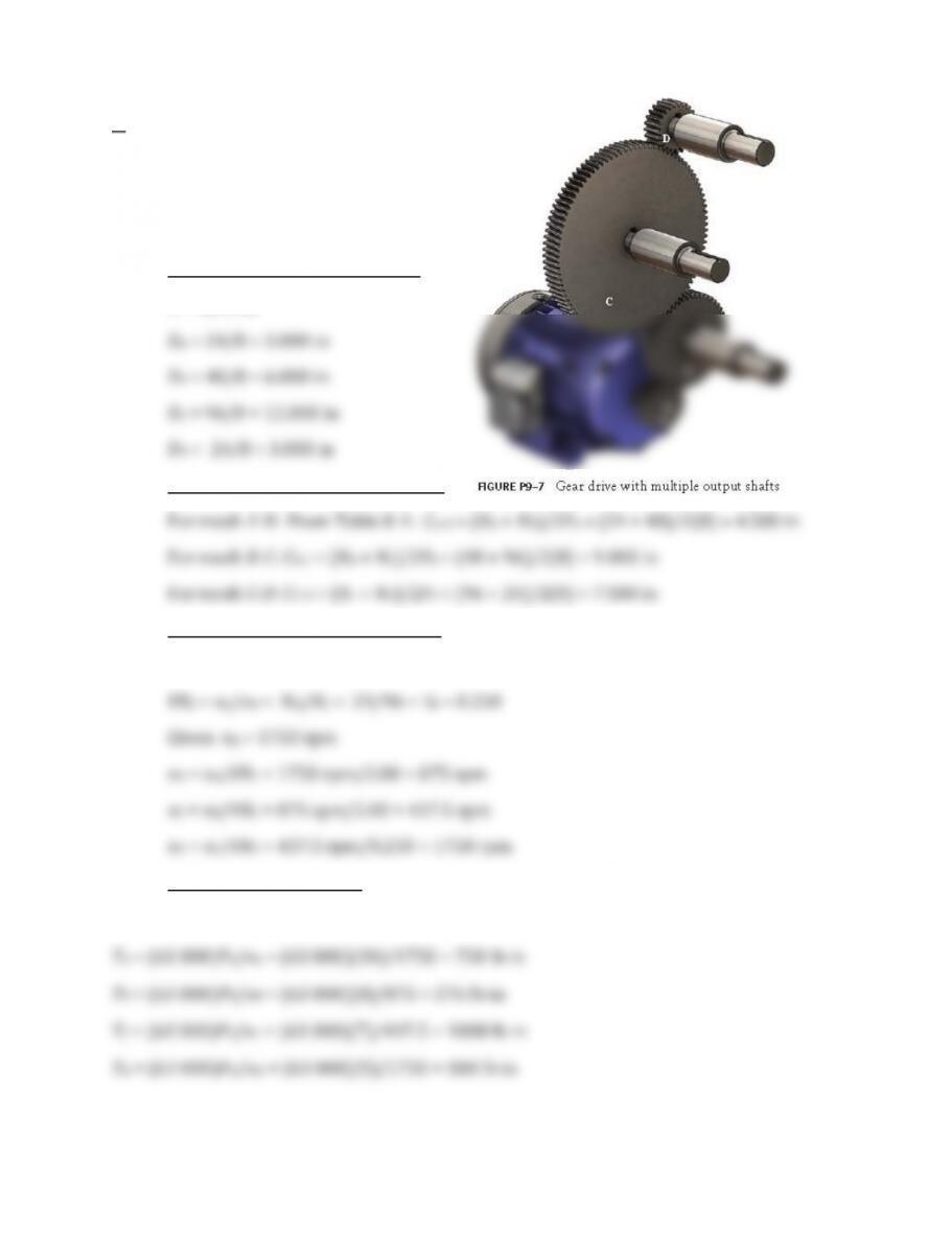
229
Ǥ Given:PdαͺǢnAαͳͷͲ
NAαʹͶǢNBαͶͺǢNCαͻǢNDαʹͶ
ǣPBαͺǢPCαǢPDαͷ
αɇȋȌαʹͲ
a.Pitchdiameterofeachgearǣ
D=NȀPd
b.Centerdistanceforeachmeshǣ
c.Rotationalspeedofeachshaftǣǣ
VR1αnAȀnBαNBȀNAαͶͺȀʹͶαʹǤͲͲͲǢVR2αnBȀnCαNCȀNBαͻȀͶͺαʹǤͲͲͲǢ
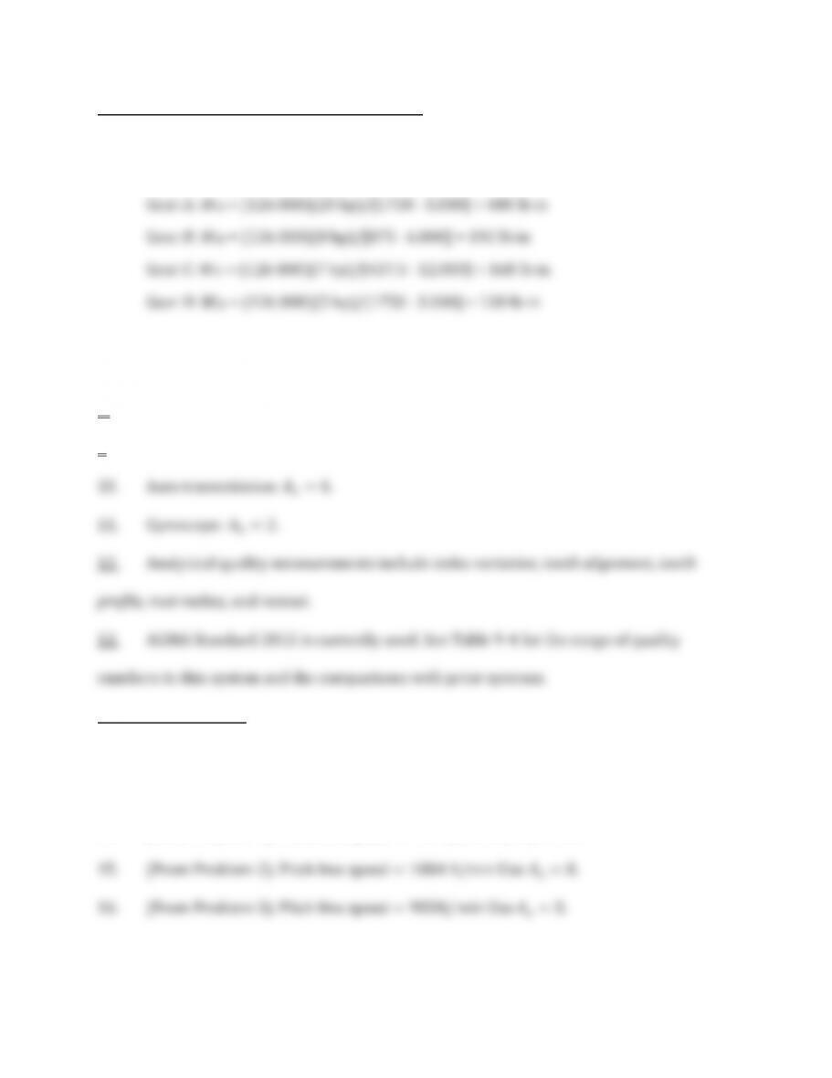
d.TorqueineachshaftǣͻǦͳͲǣTǡPǡnǣ
TαPȀnαȋ͵ͲͲͲȌPȀn
230
e.TangentialforceontheteethofeachgearǣͻǦͺǡPǡ
DǡnǡWtǡ
WtαPȀȏȋnȌȋDȀʹȌȐαȋͳʹͲͲͲȌPȀȋn
DȌ
GearQuality
ͺǤ ǣܣ௩ൌͳͲǤ
ͻǤ ǣܣ௩ൌǤ
ForProblems14Ǧ16:ǡ
ͻǦͷǤ
Ǥ
ͳͶǤ ȋͳȌǤൌ ͻͶȀܣ௩ൌ ͳͲǤ
231
GearMaterials
ͳǦʹͷͻǦͻǦͺǤ
Ǥ
ͳǤ
Ǥ
ͳͺǤ
ͳͻǤ
ʹͲǤ ͳͺͲͶͲͲǤͻǦͳͺ
ʹͳǤ ͳǤ
232
ʹʹǤ ʹ͵Ǧǡ
ʹ͵Ǥ ǡǡ
ʹͶǤ ʹͲͲͳǦͲͶȋʹͲͳȌǤ
ʹͷǤ ʹͲͲͳǦͲͶȋʹͲͳȌǡǡ
ʹǤ ͻǦͳͺͻǦͳͻǣ
Ǥ ͳǢ ʹͲͲǣݏ௧ ൌ ʹͺǤʹǢ ݏ ൌ ͻ͵ǤͷͲ െ Ǥ
ݏ
௧ ൌ ͳͻͶǤͻǢ ݏ ൌ ͶͶǤ െ
Ǥ ͳǢ͵ͲͲǣݏ௧ ൌ ͵ǤͲǢ ݏ ൌ ͳʹͷǤ െ Ǥ Ǥ
233
͵ͳǤ ͶͳͶͲǡͶ͵ͶͲǡͳͷͲǤǤ
͵ʹǤ ͷ͵ǡͺͲǦͷͷǦͲͳͻǤ
͵͵Ǥ Ǥ ݏ௧ ൌ ͶͷǤͲǢݏ ൌ ͳͲǤͲ െ Ǥ Ǥ
ݏ
௧ ൌ ͵ͳͲǢ ݏ ൌ ͳͳʹ െ ȋͻǦͻȌ
Ǥݏ
௧ ൌ ͶͷǤͲǢ ݏ ൌ ͳͷǤͲ െ Ǥ Ǥ
ݏ
௧ ൌ ͵ͳͲǢ ݏ ൌ ͳʹͲ െ ȋͻǦͻȌ
234
Ǥݏ
௧ ൌ ͳʹǤͲǢݏ െ Ǥ Ǥ
ݏ
௧ ൌ ͺ͵ǤͲǢݏ െ (Table 9-14)
͵ͶǤ ൌ ͲǤͲʹǤ(Figure 9-20)
͵ͷǤ ൌ ͲǤͻͲǤȋͻǦʹͲȌ
ǡ͵Ǧͺ͵Ǥ
ǡǡǡǤ
ǡ
Ǥ
Ǥ
x BLUEǤ
͵ͷͻǡpartsofcompleteproblem
solutions,Ǥǡ͵ǡͶʹǡ
ͶͺǡͷͶǣ
x ͵Ǥ
x ͶʹǤ
x ͶͺǤ
x ͷͶǤ
Ǥ
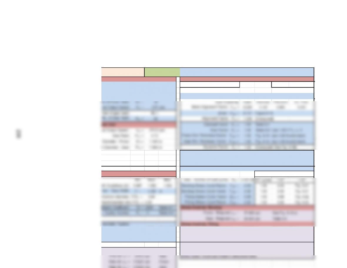
UR GEARS APPLICATION: Industrial conveyor driven by an electric motor
Problems 36, 42, 48, 54
n
put Data: Factors in Design Analysis:
Input Power: P = 10 hp Alignment Factor,K
m
=1.0+C
pf
+C
ma
If F <1.0 If F>1.0 F/D
P
= 0.83
Input Speed: n
P
=1750rpm Pinion Proportion Factor, C
pf
= 0.058 0.061 [0.50 < F/D
P
< 2.00]
Diametral Pitch: P
d
= 12 Enter: C
pf
= 0.061 Figure 9-12
O
b
er of Pinion Teeth: N
P
=18 Type of gearing: Open Commer. Precision Ex. Prec.
i
red Output Speed: n
G
= 370 rpm Mesh Alignment Factor, C
ma
= 0.268 0.147 0.083 0.051
m
ber of gear teeth: 85.1 Enter: C
ma
= 0.147 Figure 9-13
No. of Gear Teeth: N
G
= 85 Alignment Factor: K
m
= 1.208 [Computed]
u
ted data: Overload Factor: K
o
=1.50Table 9–1
u
al Output Speed: n
G
= 370.6 rpm Size Factor: K
s
=1.00Table 9–2: Use 1.00 if P
d
>= 5
Gear Ratio: m
G
= 4.72 Pinion Rim Thickness Factor: K
BP
= 1.00 Fig. 9–14: Use 1.00 if solid blank
Diameter – Pinion: D
P
=1.500 in Gear Rim Thickness Factor: K
BG
= 1.00 Fig. 9–14: Use 1.00 if solid blank
h Diameter – Gear: D
G
= 7.083 in Dynamic Factor: K
v
= 1.35 [Computed: See Fig. 9-16]
Center Distance: C = 4.292 in Service Factor: SF = 1.00 Use 1.00 if no unusual conditions
Pitch Line Speed: v
t
= 687 ft/min
Transmitted Load: W
t
= 480.19 lb Reliability Factor: K
R
= 1.00 Table 9-11 Use 1.00 for R = .99
Enter: Design Life: 20000 hours See Table 9-12
Secondary Input Data: Pinion – Number of load cycles: N
P
= 2.1E+09 Guidelines: Y
N
, Z
N
Pinion: J
P
= 0.320 Fig. 9-10 Pinion: Required s
ac
= 199,099 psi See Fig. 9-19 or
Gear: J
G
= 0.410 Fig. 9-10 Gear: Required s
ac
= 190,443 psi Table 9-9
g
Geometry Factor: I = 0.108 Fig. 9-17 Specify materials, alloy and heat treatment, for most severe requirement.
REF: m
G
= 4.72 One possible material specification:
Prob 36: s
t
= 35253 psi Pinion s
ac
too high for any form of Grade 1 steel. Recommend redesign to lower
Prob 36: s
t
= 27514 psi Gear stress levels. Could use Grade 2 carburized steel.
Prob 48: s
c
= 175207 psi Pinion
Prob 48:
s
c
=
175207
psi
Gear
R GEARS APPLICATION: Cement kiln driven by an electric motor
Problems 37, 43, 49, 55
p
ut Data: Factors in Design Analysis:
Input Power: P = 40 hp Alignment Factor,K
m
=1.0+C
pf
+C
ma
If F <1.0 If F>1.0 F/D
P
= 0.68
Input Speed: n
P
= 1150 rpm Pinion Proportion Factor, C
pf
= 0.043 0.058 [0.50 < F/D
P
< 2.00]
Diametral Pitch: P
d
= 6Enter: C
pf
= 0.058 Figure 9-12
e
r of Pinion Teeth: N
P
=20 Type of gearing: Open Commer. Precision Ex. Prec.
e
d Output Speed: n
G
= 479 rpm Mesh Alignment Factor, C
ma
= 0.284 0.162 0.096 0.061
ber of gear teeth: 48.0 Enter: C
ma
= 0.162 Figure 9-13
N
o. of Gear Teeth: N
G
= 48 Alignment Factor: K
m
= 1.22 [Computed]
e
d data: Overload Factor: K
=1.75Table 9-1
a
l Output Speed: n
G
= 479.2 rpm Size Factor: K
s
=1.00Table 9-2: Use 1.00 if P
d
>= 5
Gear Ratio: m
G
= 2.40 Pinion Rim Thickness Factor: K
BP
= 1.00 Fig. 9-14: Use 1.00 if solid blank
D
iameter – Pinion: D
P
=3.333 in Gear Rim Thickness Factor: K
BG
= 1.00 Fig. 9-14: Use 1.00 if solid blank
Diameter – Gear: D
G
= 8.000 in Dynamic Factor: K
v
= 1.42 [Computed: See Fig. 9-16]
Center Distance: C = 5.667 in Service Factor: SF = 1.00 Use 1.00 if no unusual conditions
P
itch Line Speed: v
t
= 1004 ft/min
T
ransmitted Load: W
t
= 1315 lb Reliability Factor: K
R
= 1.00 Table 9-11 Use 1.00 for R = .99
Enter: Design Life: 8000 hours See Table 9-12
Secondary Input Data: Pinion – Number of load cycles: N
P
= 5.5E+08 Guidelines: Y
N
, Z
N
Pinion: J
P
= 0.325 Fig. 9-10 Pinion: Required s
ac
= 189,152 psi See Fig. 9-19 or
Gear: J
G
= 0.395 Fig. 9-10 Gear: Required s
ac
= 185,084 psi Table 9-9
G
eometry Factor: I = 0.095 Fig. 9-17 Specify materials, alloy and heat treatment, for most severe requirement.
REF: m
G
= 2.40 One possible material specification:
Prob 37: s
t
= 32743 psi Pinion Contact stress requires case hardened Grade 2 steel.
Prob 37: s
t
= 26940 psi Gear Recommend redesign to lower stress levels.
Prob 49: s
c
= 172128 psi Pinion
GEARS APPLICATION: Small machine tool driven by an electric motor
Problems 38, 44, 50, 56
t
Data: Factors in Design Analysis:
Input Power: P = 0.5 hp Alignment Factor,K
m
=1.0+C
pf
+C
ma
If F<1.0 If F>1.0 F/D
P
= 0.67
<
Input Speed: n
P
=3450rpm Pinion Proportion Factor, C
pf
= 0.042 0.035 [0.50 < F/D
P
< 2.00]
D
iametral Pitch: P
d
= 32 Enter: C
pf
= 0.042 Figure 9-12
O
o
f Pinion Teeth: N
P
=24 Type of gearing: Open Commer. Precision Ex. Prec.
Output Speed: n
G
= 690 rpm Mesh Alignment Factor, C
ma
= 0.255 0.135 0.074 0.043
e
r of gear teeth: 120.0 Enter: C
ma
= 0.074 Figure 9-13
of Gear Teeth: N
G
= 120 Alignment Factor: K
m
= 1.12 [Computed]
d
data: Overload Factor: K
o
=1.50Table 9–1
O
e
nter Distance: C = 2.250 in Service Factor: SF = 1.25 Use 1.00 if no unusual conditions
ch Line Speed: v
t
= 677 ft/min
a
nsmitted Load: W
t
= 24.36 lb Reliability Factor: K
R
= 1.50 Table 9-11 Use 1.00 for R = .99
Enter: Design Life: 12000 hours See Table 9-12
Secondary Input Data: Pinion – Number of load cycles: N
P
= 2.5E+09 Guidelines: Y
N
, Z
N
Pinion: J
P
=0.360 Fig. 9-10 Pinion: Required s
ac
= 156,966 psi See Fig. 9-19 or
Gear: J
G
=0.440 Fig. 9-10 Gear: Required s
ac
= 151,791 psi Table 9-9
e
ometry Factor: I = 0.118 Fig. 9-17 Specify materials, alloy and heat treatment, for most severe requirement.
REF: m
G
= 5.00 One possible material specification:
Prob 38: s
t
= 8071 psi Pinion Pinion: Carburized case hardened, 55-64 HRC, s
ac
= 180,000 psi
Prob 38: s
t
= 6603 psi Gear Gear: Carburized case hardened, 55-64 HRC, s
ac
= 180,000 psi
Prob 50: s
c
= 73669 psi Pinion
Prob 50:
s
=
73669
psi
Gear
GEARS APPLICATION: Aircraft actuator driven by a universal electric motor
Problems 39, 45, 51, 57
t
Data: Factors in Design Analysis:
Input Power: P = 15 hp Alignment Factor,K
m=1.0+Cpf +Cma If F <1.0 If F>1.0 F/D P = 0.50
<
Input Speed: nP = 6500 rpm Pinion Proportion Factor, Cpf = 0.025 0.031 [0.50 < F/DP< 2.00]
D
iametral Pitch: Pd = 10 Enter: Cpf = 0.031 Figure 9-12
O
o
f Pinion Teeth: NP =30 Type of gearing: Open Commer. Precision Ex. Prec.
Output Speed: nG = 2216 rpm Mesh Alignment Factor, Cma = 0.272 0.150 0.086 0.053
e
r of gear teeth: 88.0 Enter: Cma = 0.053 Figure 9-13
of Gear Teeth: NG = 88 Alignment Factor: K m = 1.08 [Computed]
d
data: Overload Factor: K o =1.50Table 9-1
Gear Ratio: mG = 2.93 Pinion Rim Thickness Factor: K BP = 1.00 Fig. 9–14: Use 1.00 if solid blank
a
meter – Pinion: DP=3.000 in Gear Rim Thickness Factor: K BG = 1.00 Fig. 9–14: Use 1.00 if solid blank
iameter – Gear: DG = 8.800 in Dynamic Factor: Kv = 1.00 [Computed: See Fig. 9-16]
e
nter Distance: C = 5.900 in Service Factor: SF = 1.00 Use 1.00 if no unusual conditions
ch Line Speed: vt = 5105 ft/min
a
nsmitted Load: Wt = 97.0 lb Reliability Factor: K R = 1.50 Table 9-11 Use 1.00 for R = .99
Enter: Design Life: 4000 hours See Table 9-12
Secondary Input Data: Pinion – Number of load cycles: NP = 1.6E+09 Guidelines: YN, Z N
Gear: JG =0.530 Fig. 9-10 Gear: Required s ac = 62,239 psi Table 9-9
e
ometry Factor: I = 0.130 Fig. 9-17 Specify materials, alloy and heat treatment, for most severe requirement.
REF: mG = 2.93 One possible material specification:
Prob 39: st = 2285 psi Pinion Stresses are quite low for steel gears. Recommend redesign
Prob 39: st = 1983 psi Gear
Prob 51: sc = 37758 psi Pinion
Prob 51:
s
c
=
37758
psi
Gear
GEARS APPLICATION: Portable indusrial water pump driven by a gasoline engine
Problems 40, 46, 52, 58
t
Data: Factors in Design Analysis:
Input Power: P = 125 hp Alignment Factor,K
m=1.0+Cpf +Cma If F <1.0 If F>1.0 F/D P = 0.50
<
Input Speed: nP = 2500 rpm Pinion Proportion Factor, Cpf = 0.025 0.031 [0.50 < F/DP< 2.00]
D
iametral Pitch: Pd = 4Enter: Cpf = 0.031 Figure 9-12
O
o
f Pinion Teeth: NP =32 Type of gearing: Open Commer. Precision Ex. Prec.
Output Speed: nG = 1050 rpm Mesh Alignment Factor, Cma = 0.272 0.150 0.086 0.053
e
r of gear teeth: 76.2 Enter: Cma =0.15Figure 9-13
of Gear Teeth: NG = 76 Alignment Factor: K m = 1.18 [Computed]
d
data: Overload Factor: K o =1.70Table 9-1
Gear Ratio: mG = 2.38 Pinion Rim Thickness Factor: K BP = 1.00 Fig. 9–14: Use 1.00 if solid blank
a
meter – Pinion: DP=8.000 in Gear Rim Thickness Factor: K BG = 1.00 Fig. 9–14: Use 1.00 if solid blank
iameter – Gear: DG = 19.000 in Dynamic Factor: Kv = 1.56 [Computed: See Fig. 9-16]
e
nter Distance: C = 13.500 in Service Factor: SF = 1.00 Use 1.00 if no unusual conditions
ch Line Speed: vt = 5236 ft/min
a
nsmitted Load: Wt = 788 lb Reliability Factor: K R = 1.00 Table 9-11 Use 1.00 for R = .99
Enter: Design Life: 8000 hours See Table 9-12
Secondary Input Data: Pinion – Number of load cycles: NP = 1.2E+09 Guidelines: YN, Z N
Gear: JG =0.520 Fig. 9-10 Gear: Required s ac = 105,438 psi Table 9-9
e
ometry Factor: I = 0.124 Fig. 9-17 Specify materials, alloy and heat treatment, for most severe requirement.
REF: mG = 2.38 One possible material specification:
Prob 40: st = 14,850 psi Pinion Pinion: SAE 1040 WQT 1000, 269 HB, 22% elongation
Prob 40: st = 13,280 psi Gear Gear: SAE 1040 WQT 1000, 269 HB, 22% elongation
Prob 52: sc = 95,948 psi Pinion
Prob 52:
s
c
=
95 948
psi
Gear
[ForProblems60to83,singlesamplesolutionsareshownforeachsetofdata.]
GEARS APPLICATION: Lawn and garden tractor with fluid power drive
Problems 41, 47, 53, 59
t
Data: Factors in Design Analysis:
Input Power: P = 2.5 hp Alignment Factor,K
m
=1.0+C
pf
+C
ma
If F<1.0 If F>1.0 F/D
P
= 0.52
<
Input Speed: n
P
=680rpm Pinion Proportion Factor, C
pf
= 0.027 0.030 [0.50 < F/D
P
< 2.00]
D
iametral Pitch: P
d
= 10 Enter: C
pf
= 0.03 Figure 9-12
O
o
f Pinion Teeth: N
P
=24 Type of gearing: Open Commer. Precision Ex. Prec.
Output Speed: n
G
= 263 rpm Mesh Alignment Factor, C
ma
= 0.268 0.147 0.083 0.051
e
r of gear teeth: 62.1 Enter: C
ma
= 0.147 Figure 9-13
of Gear Teeth: N
G
= 62 Alignment Factor: K
m
= 1.18 [Computed]
d
data: Overload Factor: K
o
= 1.75 Table 9–1
O
utput Speed: n
G
= 263.2 rpm Size Factor: K
s
= 1.00 Table 9-2: Use 1.00 if P
d
>= 5
Gear Ratio: m
G
= 2.58 Pinion Rim Thickness Factor: K
BP
= 1.00 Fig. 9-14: Use 1.00 if solid blank
a
meter – Pinion: D
P
=2.400 in Gear Rim Thickness Factor: K
BG
= 1.00 Fig. 9-14: Use 1.00 if solid blank
i
ameter – Gear: D
G
= 6.200 in Dynamic Factor: K
v
= 1.28 [Computed: See Fig. 9–16]
e
nter Distance: C = 4.300 in Service Factor: SF = 1.25 Use 1.00 if no unusual conditions
c
h Line Speed: v
t
= 427 ft/min
nsmitted Load: W
t
= 193.09 lb Reliability Factor: K
R
= 0.85 Table 9-11 Use 1.00 for R = .99
Enter: Design Life: 2000 hours See Table 9-12
Secondary Input Data: Pinion – Number of load cycles: N
P
= 8.2E+07 Guidelines: Y
N
, Z
N
p
Pinion: J
P
= 0.430 Fig. 9–10 Pinion: Required s
ac
= 87,531 psi See Fig. 9-19 or
Gear: J
G
= 0.500 Fig. 9-10 Gear: Required s
ac
= 85,727 psi Table 9-9
e
ometry Factor: I = 0.122 Fig. 9-17 Specify materials, alloy and heat treatment, for most severe requirement.
REF: m
G
= 2.58 One possible material specification:
Prob 41: s
t
= 9458 psi Pinion Pinion: Ductile iron 100-70-03 Q&T, s
ac
= 92 000 psi, s
at
= 27 000 psi
Prob 41: s
t
= 8134 psi Gear Gear: Ductile iron 100-70-03 Q&T, s
ac
= 92 000 psi, s
at
= 27 000 psi
Prob 53: s
c
= 78263 psi Pinion
Prob 53:
s
=
78263
psi
Gear
G
EARS APPLICATION: Reciprocating compressor driven by an electric motor
Problem 60
Data: Factors in Design Analysis:
Input Power: P = 5 hp Alignment Factor,K
m
=1.0+C
pf
+C
ma
If
F
<1.0 If F>1.0 F/D
P
= 0.69
Input Speed: n
P
=1200rpm Pinion Proportion Factor, C
pf
= 0.044 0.048 [0.50 < F/D
P
< 2.00]
ametral Pitch: P
d
= 10 Enter: C
pf
= 0.048 Figure 9-12
f
Pinion Teeth: N
P
=18 Type of gearing: Open Commer. Precision Ex. Prec.
O
utput Speed: n
G
= 387.5 rpm Mesh Alignment Factor, C
ma
= 0.268 0.147 0.083 0.051
r
of gear teeth: 55.7 Enter: C
ma
=0.147Figure 9-13
of Gear Teeth: N
G
= 56 Alignment Factor: K
m
= 1.20 [Computed]
data: Overload Factor: K
o
=1.50Table 9-1
e
nter Distance: C = 3.700 in Service Factor: SF = 1.00 Use 1.00 if no unusual conditions
c
h Line Speed: v
t
= 565 ft/min
n
smitted Load: W
t
= 292 lb Reliability Factor: K
R
= 1.00 Table 9-11 Use 1.00 for R = .99
Enter: Design Life: 20000 hours See Table 9-12
Secondary Input Data: Pinion – Number of load cycles: N
P
= 1.4E+09 Guidelines: Y
N
, Z
N
G
cycles >10
<10
G
o
Pinion: J
P
= 0.320 Fig. 9-10 Pinion: Required s
ac
= 143,088 psi See Fig. 9-19 or
Gear: J
G
= 0.400 Fig. 9-10 Gear: Required s
ac
= 138,422 psi Table 9-9
o
metry Factor: I = 0.100 Fig. 9-17 Specify materials, alloy and heat treatment, for most severe requirement.
REF: m
G
= 3.11 One possible material specification:
s
tresses: s
t
= 17245 psi Pinion Pinion: Requires HB 354: SAE 4140 OQT 900; HB 388, 16% elongation
O
A
RS APPLICATION: Milling machine driven by an electric motor
Problem 61
a
ta: Factors in Design Analysis:
n
put Power: P = 20 hp Alignment Factor,K
m
=1.0+C
pf
+C
ma
If F<1.0 If F>1.0 F/D
P
= 0.50
n
put Speed: n
P
= 550 rpm Pinion Proportion Factor, C
pf
= 0.025 0.038 [0.50 < F/D
P
< 2.00]
m
etral Pitch: P
d
= 6Enter: C
pf
= 0.038 Figure 9-12
f
e
r Distance: C = 7.917 in Service Factor: SF = 1.00 Use 1.00 if no unusual conditions
L
ine Speed: v
t
= 576 ft/min
m
itted Load: W
t
= 1146 lb Reliability Factor: K
R
= 1.25 Table 9-11 Use 1.00 for R = .99
Enter: Design Life: 20000 hours See Table 9-12
e
condary Input Data: Pinion – Number of load cycles: N
P
= 6.6E+08 Guidelines: Y
N
, Z
N
Pinion: J
P
=0.350 Fig. 9-10 Pinion: Required s
ac
= 164,319 psi See Fig. 9-19 or
Gear: J
G
=0.420 Fig. 9-10 Gear: Required s
ac
= 160,785 psi Table 9-9
etry Factor: I = 0.108 Fig. 9-17 Specify materials, alloy and heat treatment, for most severe requirement.
REF: m
G
= 2.96 One possible material specification:
e
sses: s
t
= 20033 psi Pinion Pinion: SAE 4140 OQT 800; HB 352; 21% elong.-core; Case harden to HRC 50 min
s
t
= 16694 psi Gear Gear: SAE 4140 OQT 800; HB 352; 21% elong.-core; Case harden to HRC 50 min
s
c
= 119624 psi Pinion
G
EARS APPLICATION: Punch press driven by an electric motor
Problem 62
Data: Factors in Design Analysis:
Input Power: P = 50 hp Alignment Factor,K
m=1.0+Cpf +Cma If F<1.0 If F>1.0 F/D P = 0.50
Input Speed: nP = 900 rpm Pinion Proportion Factor, Cpf = 0.025 0.050 [0.50 < F/DP< 2.00]
ametral Pitch: Pd = 4Enter: Cpf = 0.050 Figure 9-12
f
Pinion Teeth: NP =24 Type of gearing: Open Commer. Precision Ex. Prec.
O
utput Speed: nG = 227.5 rpm Mesh Alignment Factor, Cma = 0.296 0.173 0.105 0.068
r
of gear teeth: 94.9 Enter: Cma =0.173Figure 9-13
o
f Gear Teeth: NG = 95 Alignment Factor: K m = 1.22 [Computed]
d
ata: Overload Factor: K o = 1.75 Table 9-1
O
utput Speed: nG = 227.4 rpm Size Factor: K s = 1.05 Table 9-2: Use 1.00 if Pd>= 5
Gear Ratio: mG = 3.96 Pinion Rim Thickness Factor: K BP = 1.00 Fig. 9-14: Use 1.00 if solid blank
m
eter – Pinion: DP=6.000 in Gear Rim Thickness Factor: K BG = 1.00 Fig. 9-14: Use 1.00 if solid blank
a
meter – Gear: DG = 23.750 in Dynamic Factor: Kv = 1.50 [Computed: See Fig. 9-16]
nter Distance: C = 14.875 in Service Factor: SF = 1.00 Use 1.00 if no unusual conditions
c
h Line Speed: vt = 1414 ft/min
n
smitted Load: Wt = 1167 lb Reliability Factor: K R = 1.25 Table 9-11 Use 1.00 for R = .99
Enter: Design Life: 20000 hours See Table 9-12
Secondary Input Data: Pinion – Number of load cycles: NP = 1.1E+09 Guidelines: YN, Z N
m
Gear: JG = 0.420 Fig. 9-10 Gear: Required s ac = 135,211 psi Table 9-9
o
metry Factor: I = 0.114 Fig. 9-17 Specify materials, alloy and heat treatment, for most severe requirement.
REF: mG = 3.96 One possible material specification:
s
tresses: st = 14539 psi Pinion Pinion: Requires HB 344; SAE 1040 WQT 800; HB 352; 21% elong.
st = 12462 psi Gear Gear: Requires HB 330: SAE 1040 WQT 800; HB 352; 21% elong.
sc = 100597 psi Pinion
s
=
100597
psi
Gear