
Chapter 8: Motion and Power Transmission
255
Chapter 8
Solutions
261
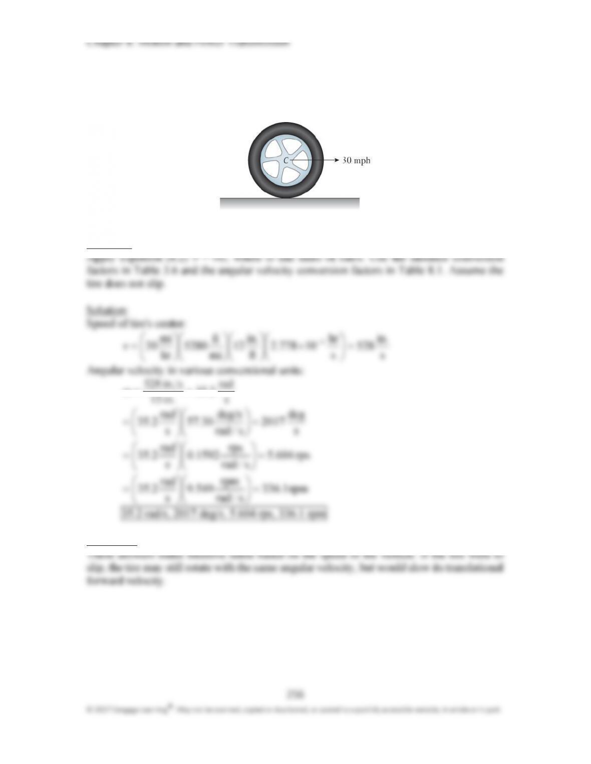
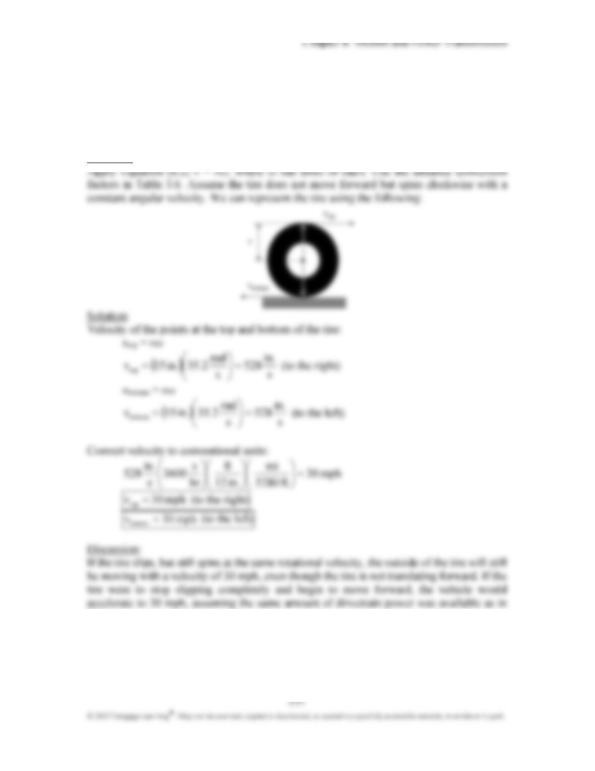
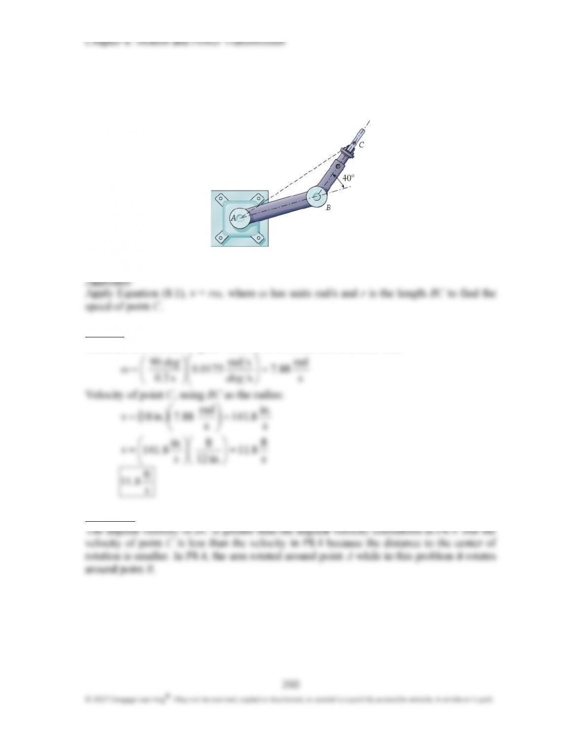
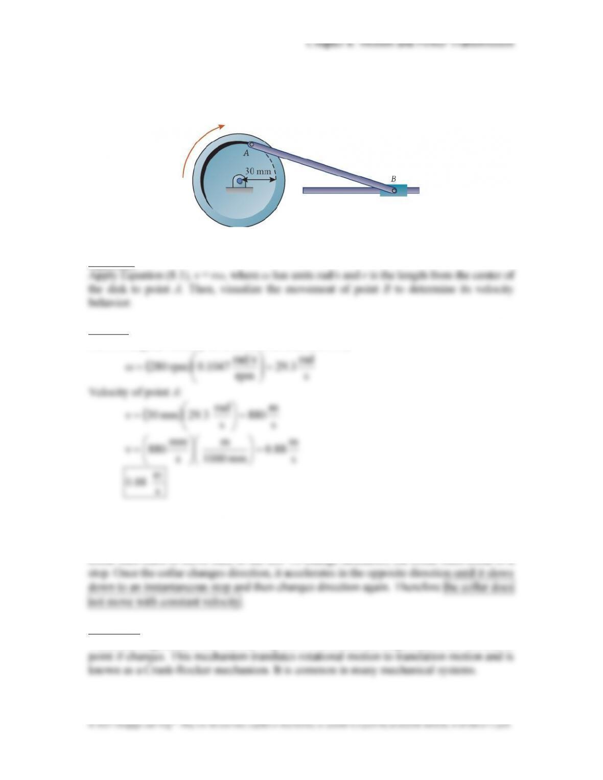
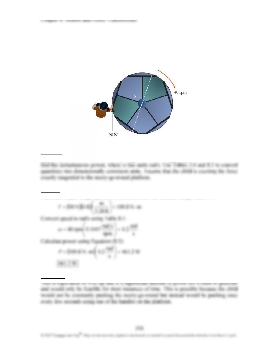
P8.6: The driving disk spins at a constant 280 rpm clockwise. Determine the velocity of the
connecting pin at A. Also, does the collar at B move with constant velocity? Explain
your answer.
Approach:
Solution:
Convert angular velocity to consistent units (Table 8.1):
rad
srad
s
Velocity of point B (collar):
The collar moves to the right when point A is moving down the right-hand side of the
driving disk. Once point A moves through the bottom of the disk to the left-hand side, the
collar then starts to move back to the left. To change directions, the collar must come to a
Discussion:
While the magnitude of the velocity of point A is constant, the magnitude of the velocity of
262
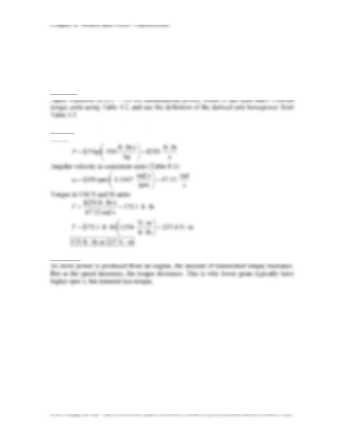
P8.7: A gasoline-powered engine produces 15 hp as it drives a water pump at a
construction site. If the engine’s speed is 450 rpm, determine the torque T that is
transmitted from the output shaft of the engine to the pump. Express your answer in the
units of ft lb and N m.
Approach:
Solution:
Power:
lbft
slbft
Discussion:
264
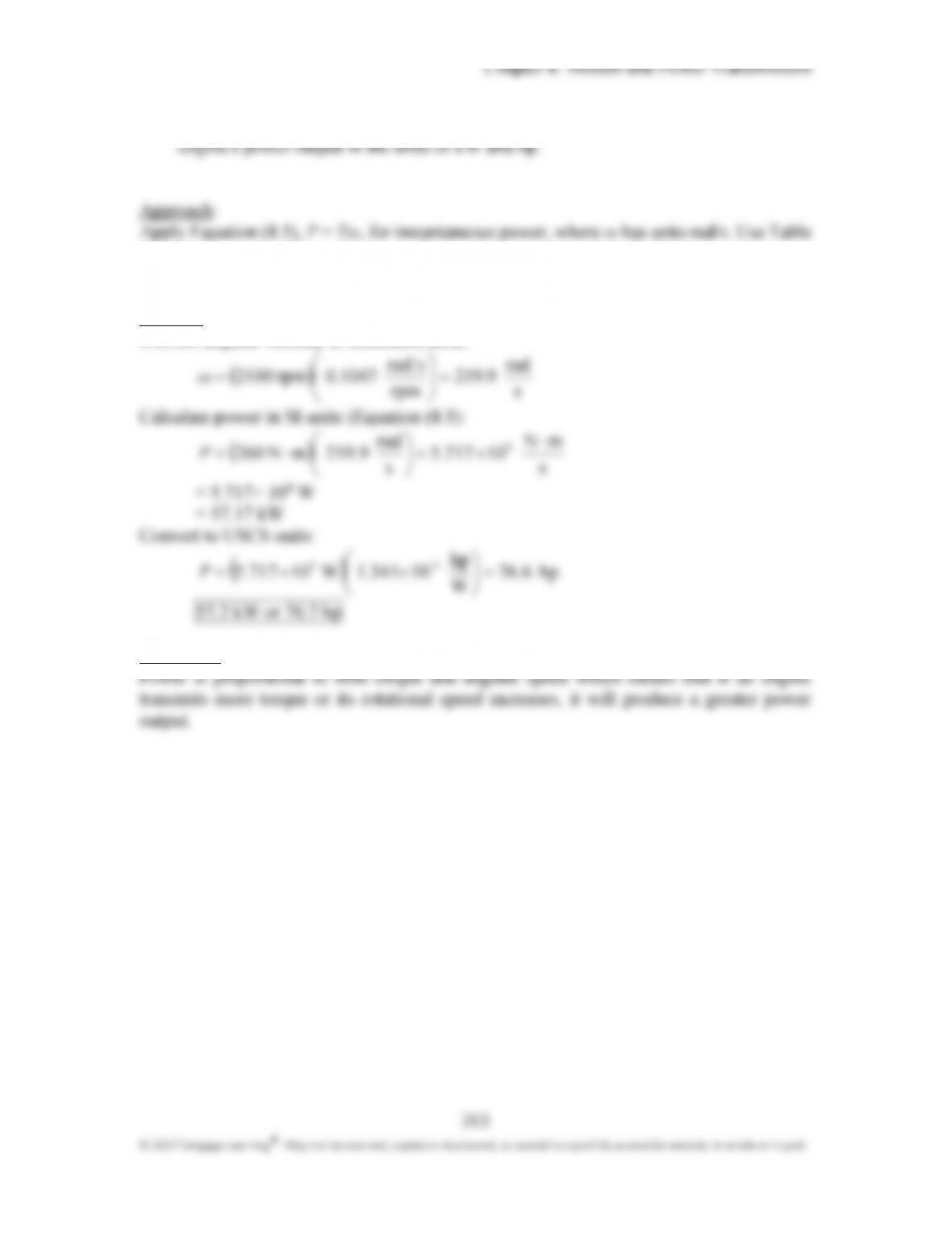
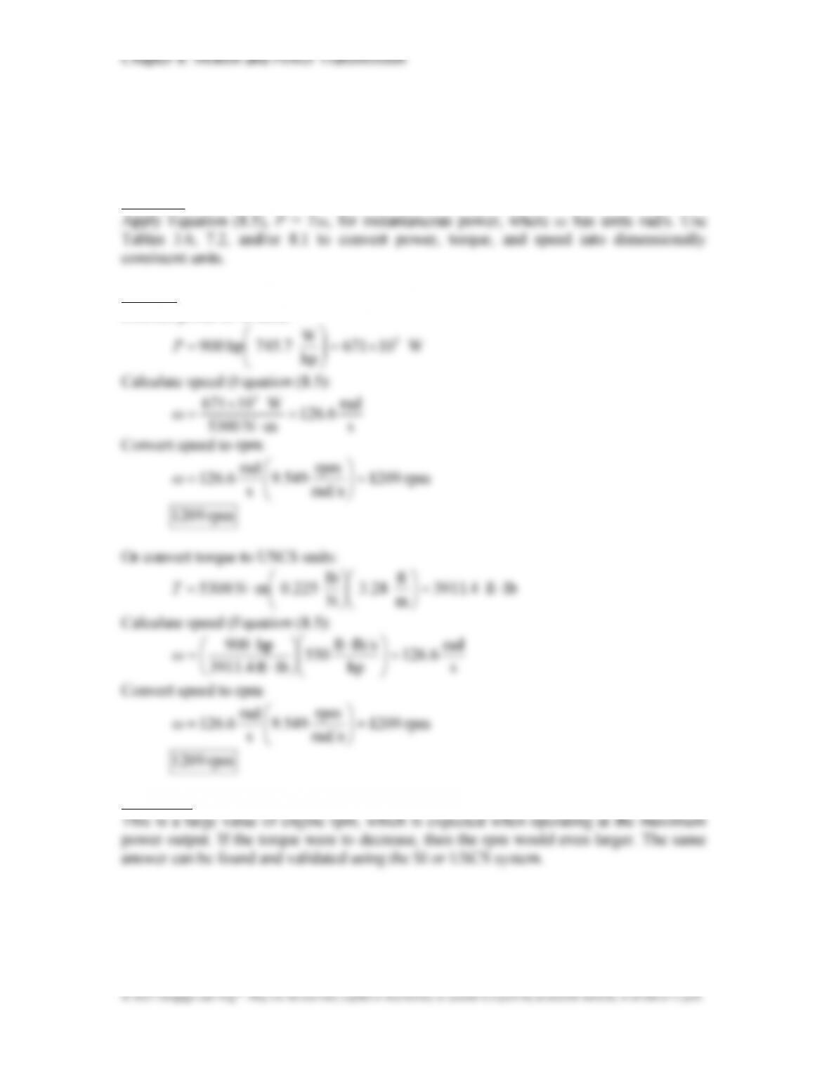
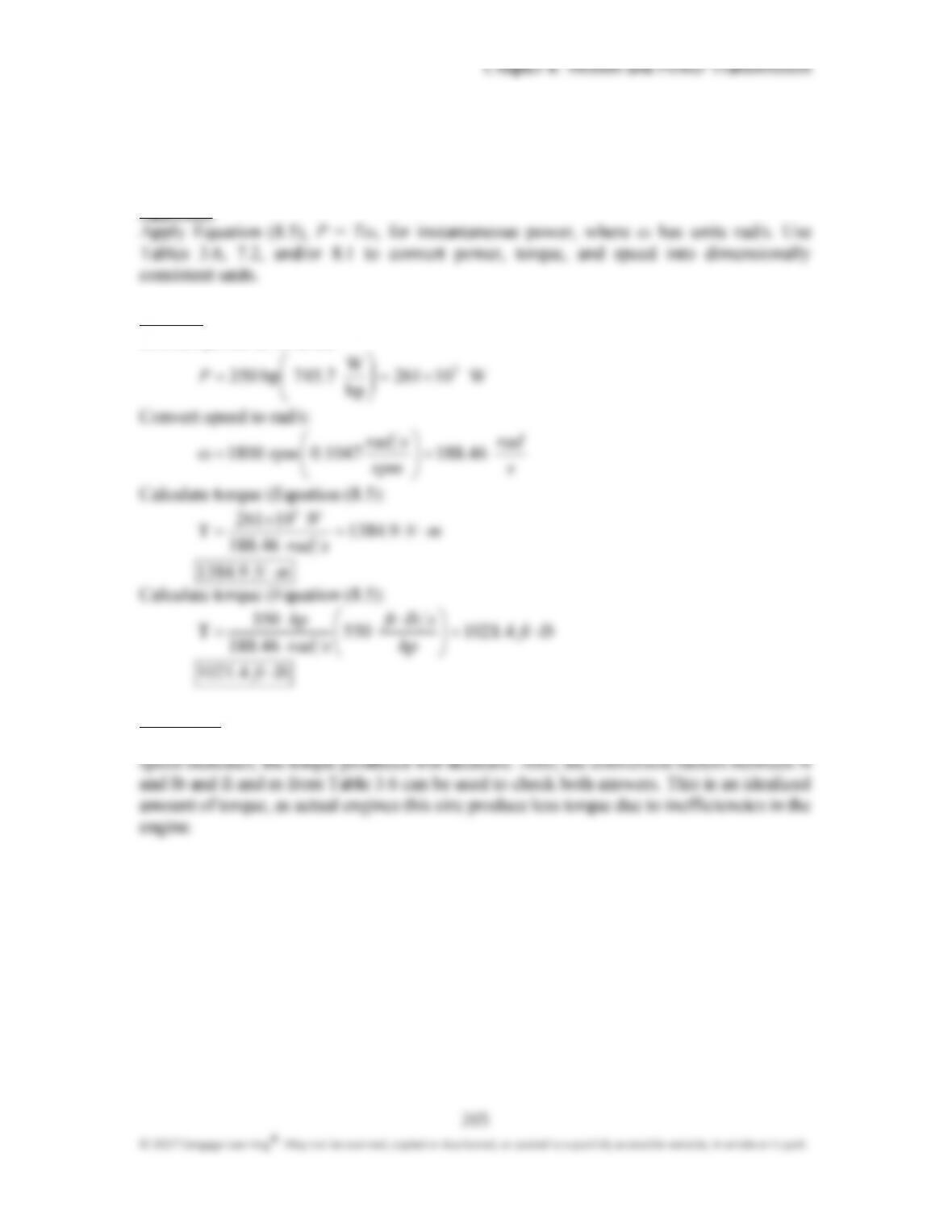
P8.9: A diesel engine for marine propulsion applications produces a maximum power of
900 hp and torque of 5300 N m. Determine the engine speed necessary for this
production in rpm.
Approach:
Solution:
Convert power to SI units:
W
Discussion:
267
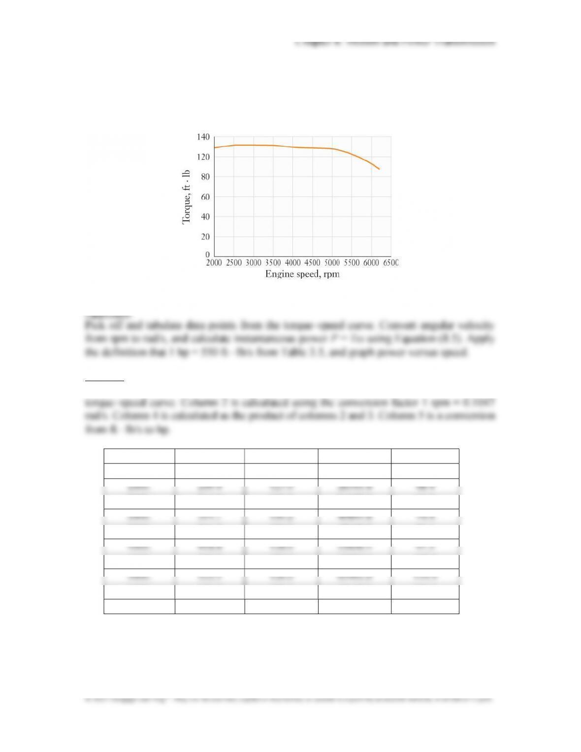
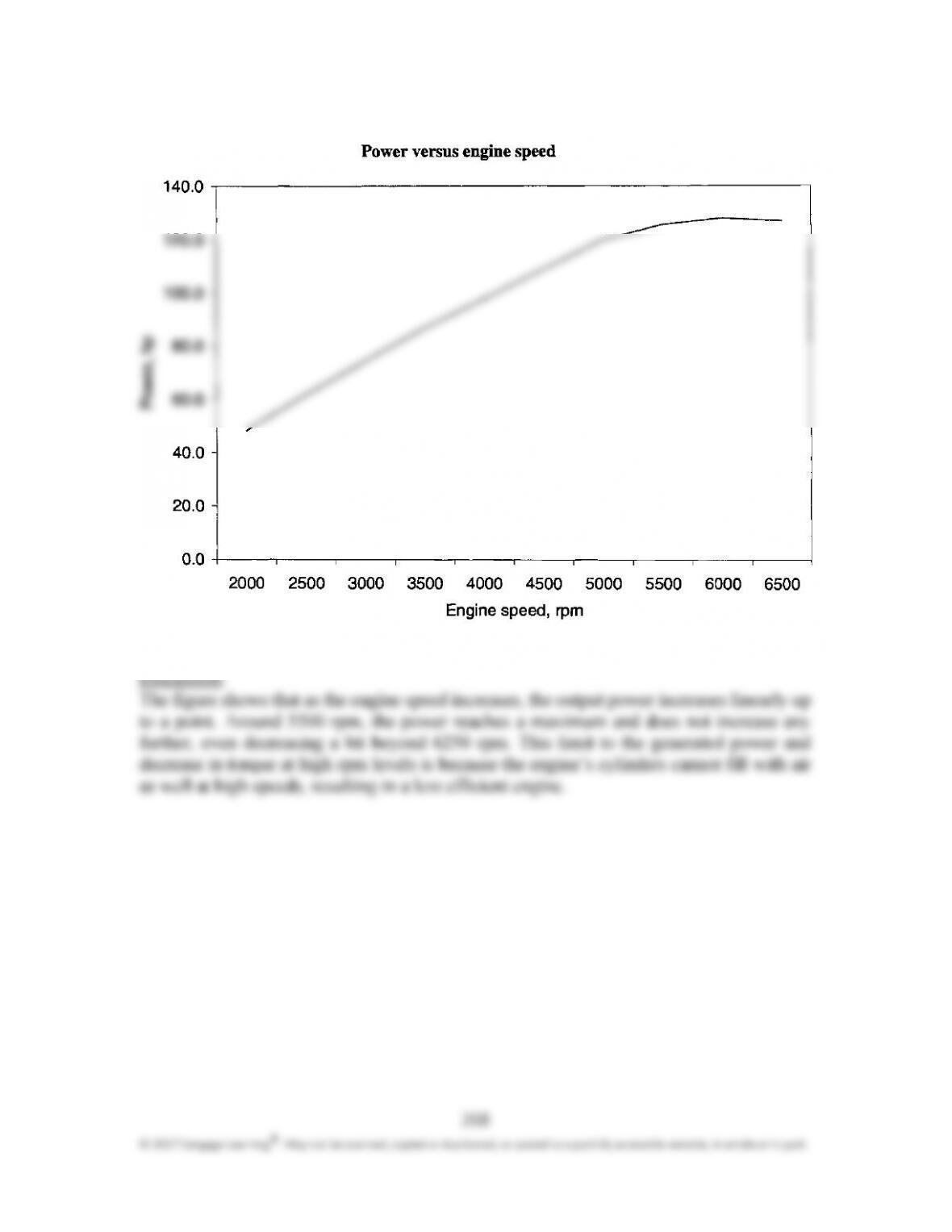
P8.12: The torque produced by a 2.5 L automobile engine operating at full throttle was
measured over a range of speeds. By using this graph of torque as a function of the
engine’s speed, prepare a second graph to show how the power output of the engine (in
the units of hp) changes with speed (in rpm).
Approach:
Solution:
Columns 1 and 3 of the following table are data points measured off the supplied
1 2 3 4 5
Speed (rpm) Speed (rad/s) Torque (ftlb) Power (ftlb/s) Power (hp)
2500. 261.8 130.0 34027.5 61.9
3500. 366.5 130.0 47638.5 86.6
4500. 471.2 127.0 59836.1 108.8
5500. 575.9 120.0 69102.0 125.6
6000. 628.2 112.0 70358.4 127.9
Chapter 8: Motion and Power Transmission
269
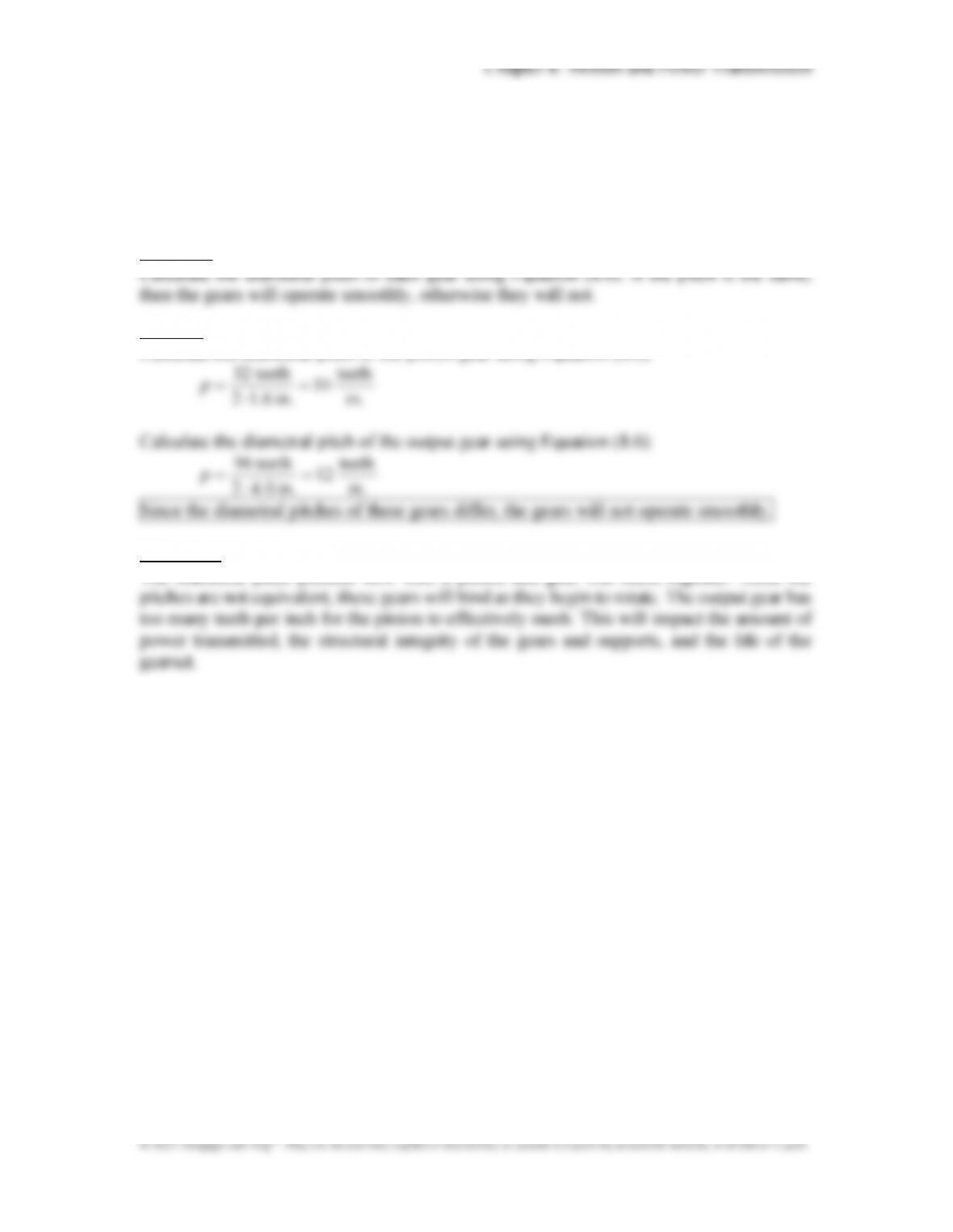
P8.13: A spur gearset has been designed with the following specifications:
Pinion gear: number of teeth = 32, diameter = 3.2 in.
Output gear: number of teeth = 96, diameter = 8.0 in.
Determine whether this gearset will operate smoothly.
Approach:
Solution:
Calculate the diametral pitch of the pinion gear using Equation (8.6):
.
.
.
p
in
teeth
10
in
6
1
2
teeth 32
Calculate the diametral pitch of the output gear using Equation (8.6):
.
.
.
p
in
teeth
12
in
0
4
2
teeth 69
Since the diametral pitches of these gears differ, the gears will not operate smoothly.
Discussion:
The diametral pitch predicts how well a pinion and gear will mesh together. Since the
270
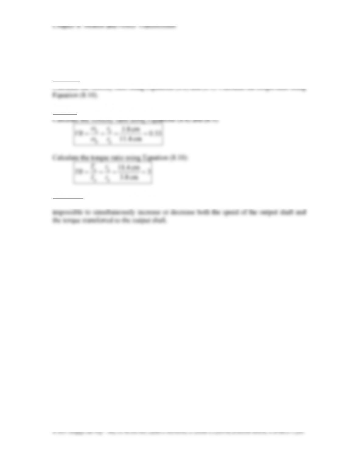
P8.14: The radius of an input pinion is 3.8 cm, and the radius of an output gear is 11.4 cm.
Calculate the velocity and torque ratios of the gearset.
Approach:
Solution:
cm .83
p
p
r
T
Discussion:
As expected, the torque ratio is the reciprocal of the velocity ratio. This means it is
271
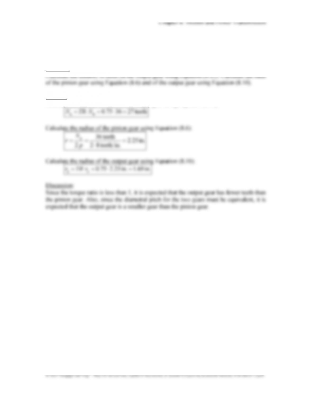
P8.15: The torque ratio of a gearset is 0.75. The pinion gear has 36 teeth and a diametral
pitch of 8. Determine the number of teeth on the output gear and the radii of both gears.
Approach:
Solution:
Calculate the number of teeth of the output gear using Equation (8.11):

272
P8.16: You are designing a geartrain with three spur gears: one input gear, one idler gear,
and one output gear. The diametral pitch for the geartrain is 16. The diameter of the
input gear needs to be twice the diameter of the idler gear and three times the diameter
of the output gear. The entire geartrain needs to fit into a rectangular footprint of no
larger than 16 in. high and 24 in. long. Determine an appropriate number of teeth and
diameter of each gear.
Approach:
Given the required geometrical relationship between the gear diameters, develop
expressions for the diameter of the idler and output gears as functions of the input gear
Solution:
Develop expressions for the diameter of the idler and output gears:
2
1
2
d
d
3
1
3
d
d
Horizontal constraint:
.ddd in 24
321
dd
11
Vertical constraint:
Since gear 1 is the largest, its diameter will be constrained by the vertical restriction.
Chapter 8: Motion and Power Transmission
273
© 2017 Cengage Learning®. May not be scanned, copied or duplicated, or posted to a publicly accessible website, in whole or in part.
.
.
din 6
2
in 12
2 .
.
din 4
3
in 12
3
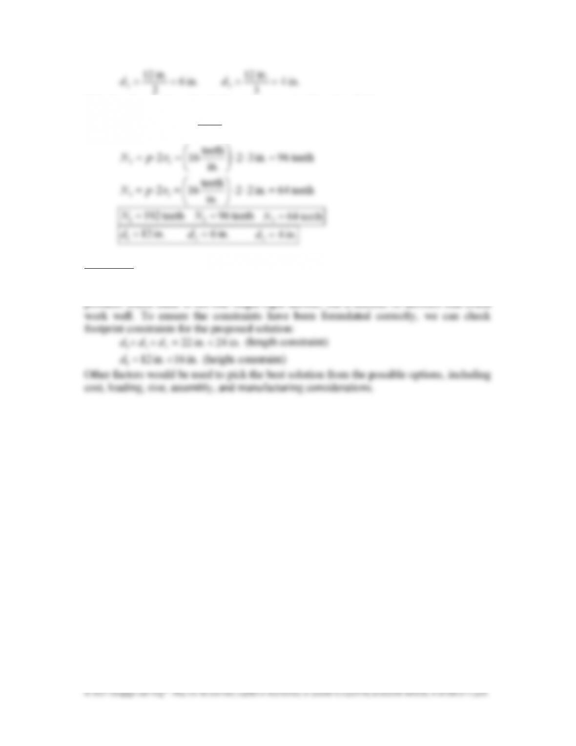
Calculate the number of teeth for each gear using Equation (8.6):
teeth 192in 62
in
teeth
162 11
.
.
rpN
teeth
Discussion:
While this combination of gear diameters solves the problem, there are numerous other
possible combinations that could work. This problem is closer to an engineering design
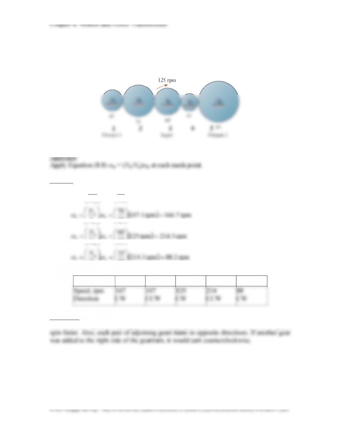
P8.17: The helical gears in the simple geartrain have teeth numbers as labeled. The central
gear rotates at 125 rpm and drives the two output shafts. Determine the speeds and
rotation directions of each shaft.
Solution:
rpm 1107rpm 125
60
3
3
2.
N
85
5
N
Gear 1 2 3 4 5
Discussion:
The rotational speed of each gear is inversely proportional to its size. The smaller gears
1
2
3
4
5