290
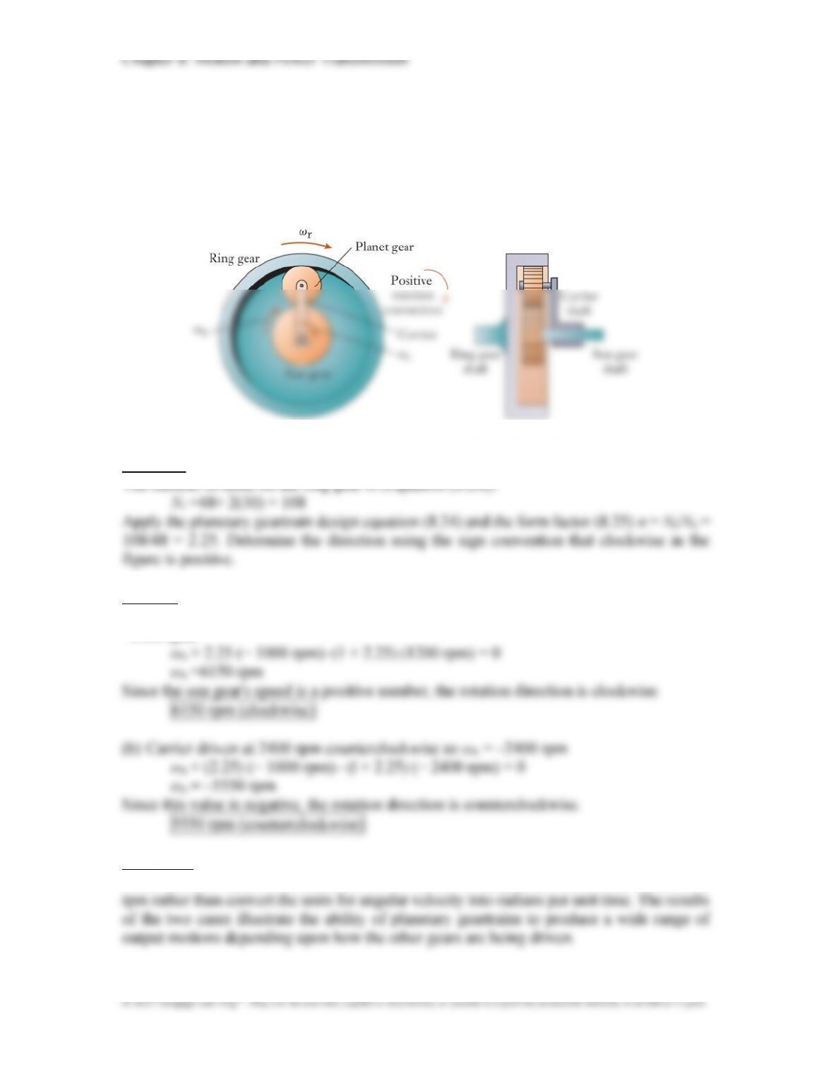
P8.29: A planetary geartrain with Ns = 48 and Np = 30 uses the carrier and ring gear as
inputs and the sun gear as output. When viewed from the right-hand side in Figure 8.36,
the hollow carrier shaft is driven at 1200 rpm clockwise, and the shaft for the ring gear
is driven at 1000 rpm counterclockwise. (a) Determine the speed and rotation direction
of the sun gear. (b) Repeat the calculation for the case in which the carrier is instead
driven counterclockwise at 2400 rpm.
Approach:
Solution:
(a) Carrier driven at 1200 rpm clockwise. Input shaft speeds are ωc = 1200 rpm and ωr =
–1000 rpm:
Discussion:
Since the form factor is a dimensionless number, it is acceptable to use the dimensions of
291
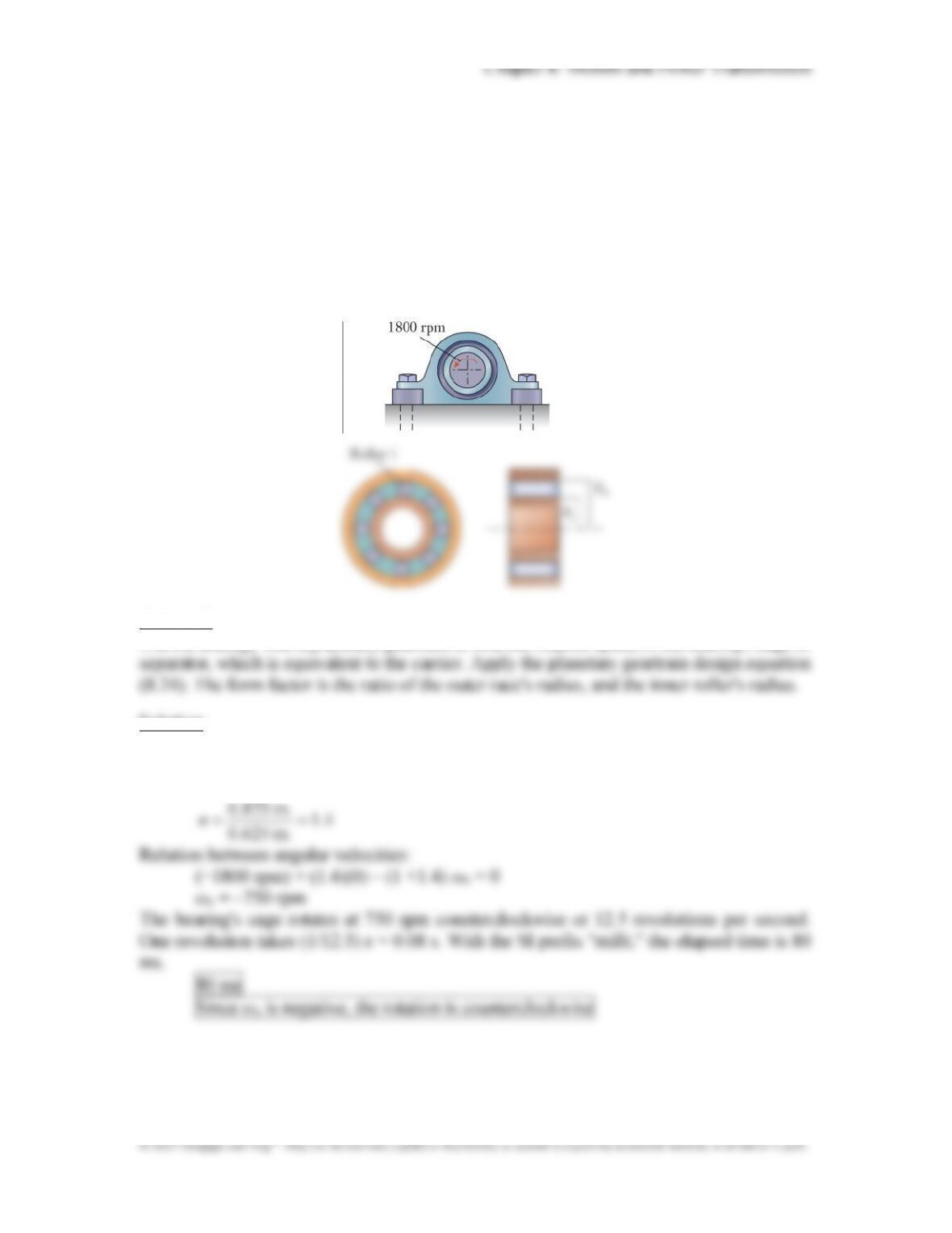
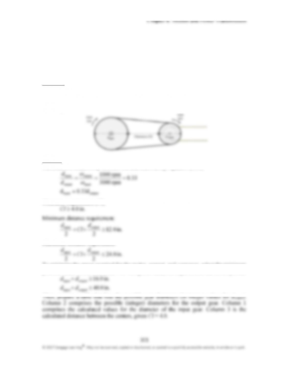
P8.30: Rolling element bearings (Section 4.6) are analogous to the layout of a balanced
planetary geartrain. The rotations of the rollers, separator, inner race, and outer race
are similar to those of the planets, carrier, sun gear, and ring gear, respectively, in a
planetary geartrain. The outer race of the straight roller bearing shown is held by a
pillow-block mount. The inner race supports a shaft that rotates at 1800 rpm. The
radii of the inner and outer races are Ri = 0.625 in. and Ro = 0.875 in. In the units of
ms, how long does it take for roller 1 to orbit the shaft and return to the topmost
position in the bearing? Does the roller orbit in a clockwise or counterclockwise
direction?
Approach:
Use the analogy with a planetary geartrain to find the rotation speed of the bearing’s cage or
Solution:
Inner race speed (negative since counterclockwise): ωs = –1800 rpm
Outer race speed (since it is held stationary): ωr = 0
Form factor:
in 8750 .
..

Chapter 8: Motion and Power Transmission
292
Discussion:
Equation (8.24) is a general planetary geartrain relationship that can be applied to a number
294
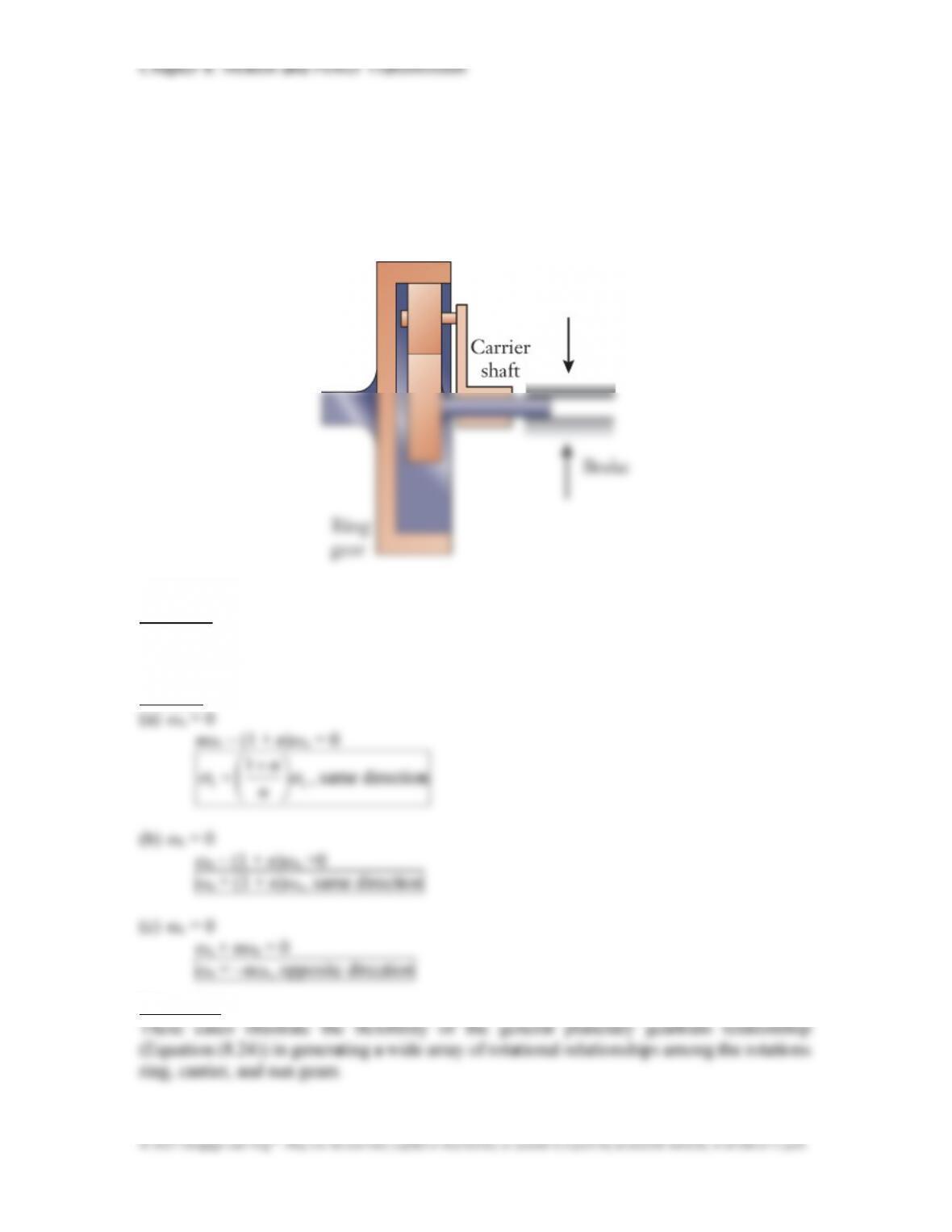
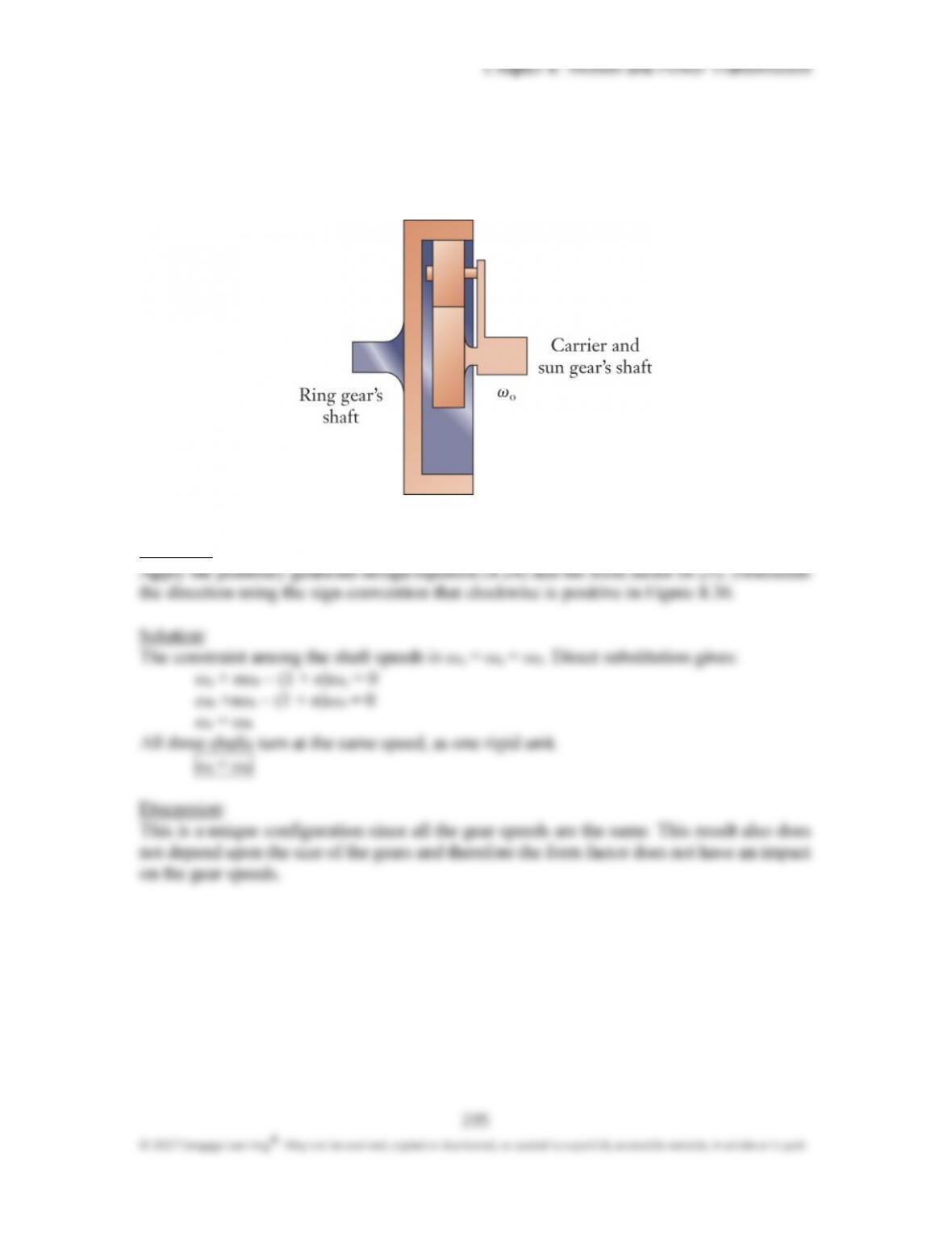
P8.32: (a) The shaft of the sun gear in the planetary geartrain is held stationary by a brake.
Determine the relationship between the rotational speeds of the shafts for the ring
gear and carrier. Do those shafts rotate in the same direction or opposite directions?
(b) Repeat the exercise for the case in which the ring gear shaft is instead held
stationary. (c) Repeat the exercise for the case in which the carrier shaft is instead
held stationary.
Approach:
Apply the planetary geartrain design equation (8.24) and the form factor (8.25). Determine
the direction using the sign convention that clockwise in Figure 8.36 is positive.
Solution:
Discussion:
296
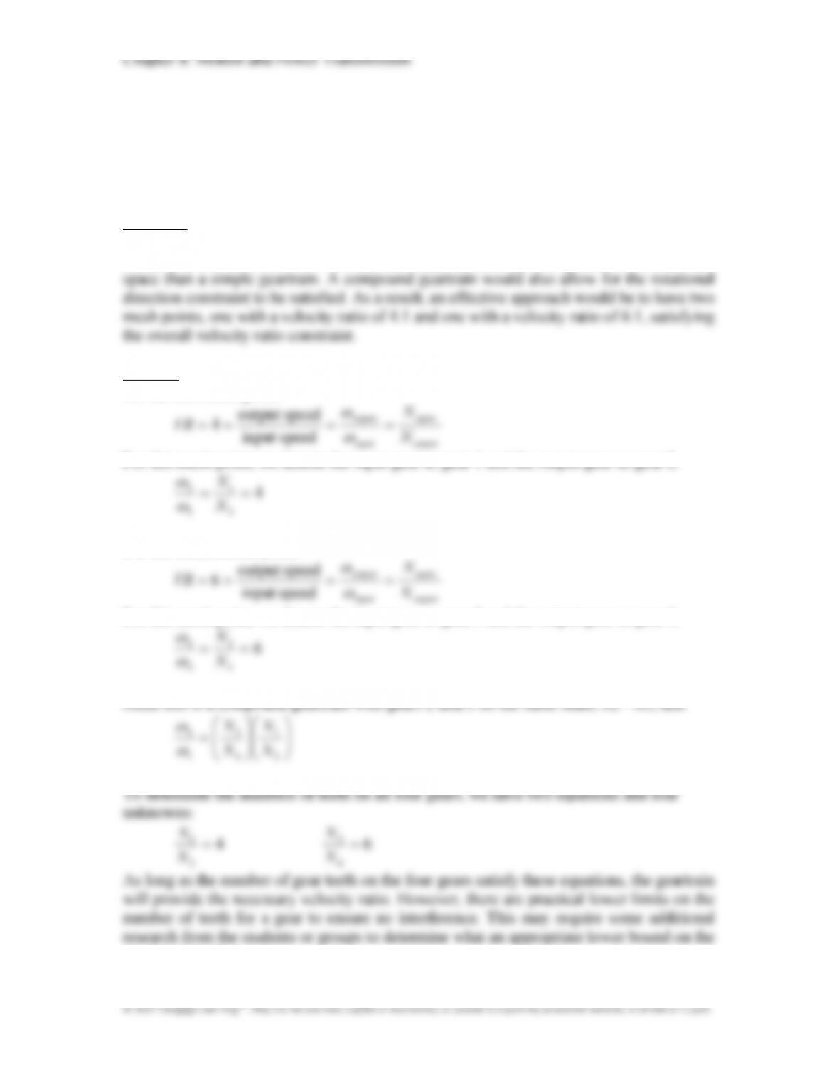
P8.34*: A gearbox is to be designed to provide an overall velocity ratio of exactly 24:1,
while minimizing the overall size of the gearbox. Also, the rotational direction of the
input and output shafts should be the same. Determine appropriate values for the
number of teeth for each gear.
Approach:
Because the velocity ratio is significantly larger than 10, the solution will require than a
simple gear and pinion. Also, since size is a constraint, a compound geartrain could use less
Solution:
For the first mesh point:
output
input
input
output
N
N
VR
speedinput
speedoutput
4
For this mesh point, we denote the input gear as gear 1 and the output gear as gear 2.
2
1
1
2 N
N
For the second mesh point:
output
input
input
output
N
N
VR
speedinput
speedoutput
6
For this mesh point, we denote the input gear as gear 3 and the output gear as gear 4.
4
3
3
4 N
N
2
4
1
N
N
number of teeth may be.
Chapter 8: Motion and Power Transmission
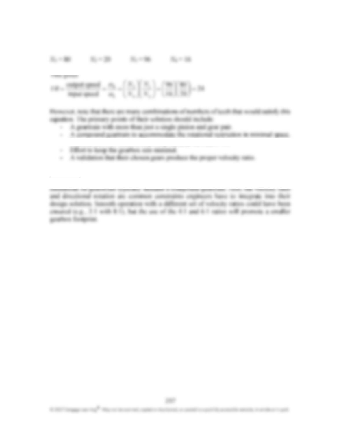
A reasonable answer would be:
– Velocity ratios of each mesh point preferably between 5-10.
Discussion:
This open-ended design problem is common in gear design. The space (and weight)
Chapter 8: Motion and Power Transmission
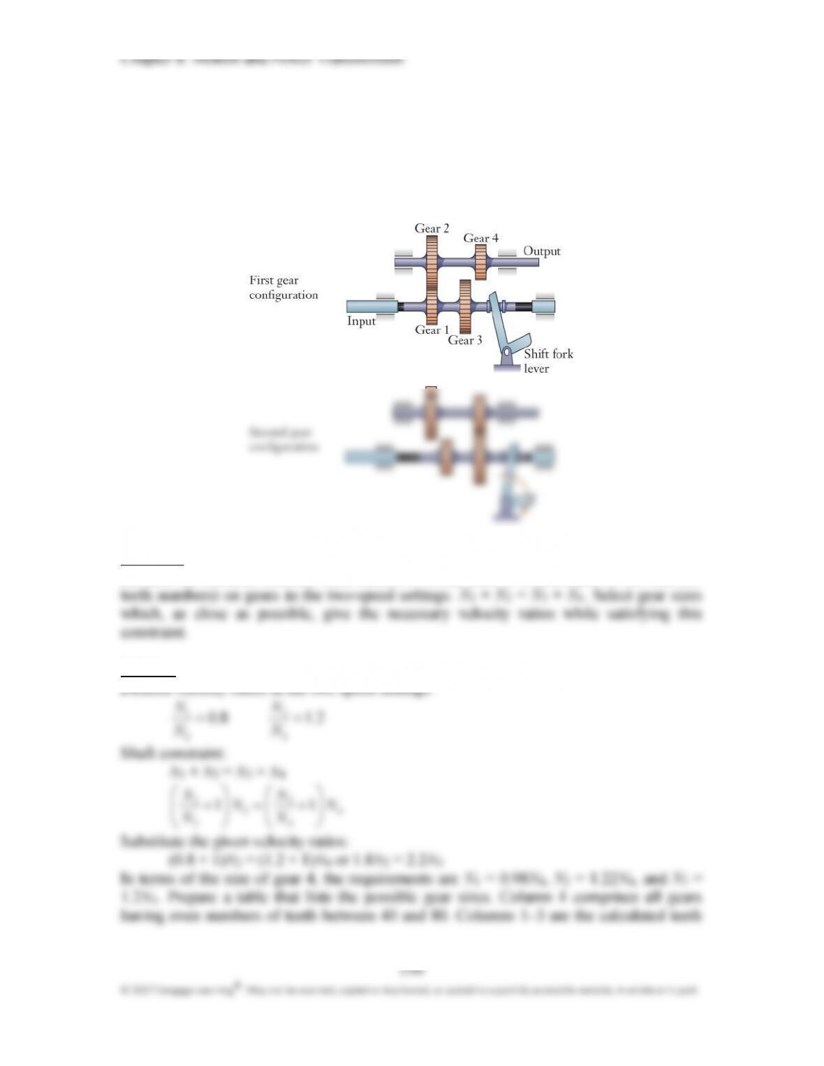
299
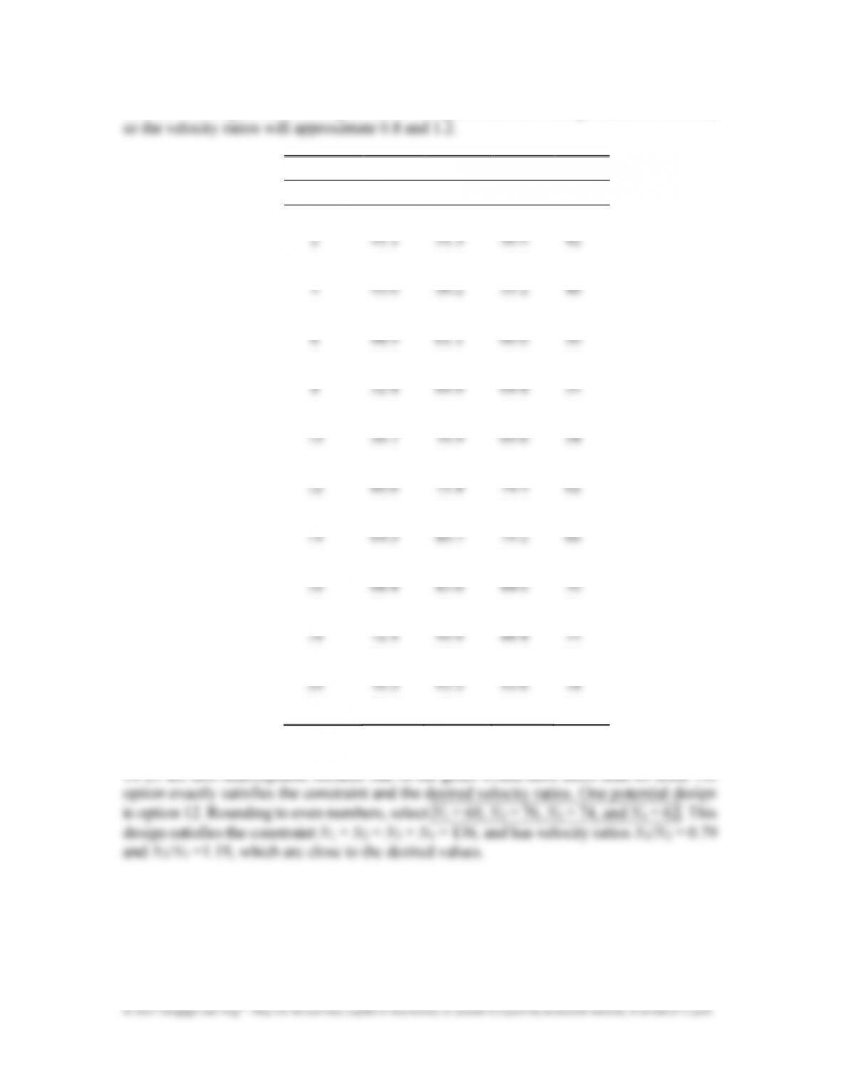
numbers which give the desired gear ratios. The gears must have integer numbers of teeth,
1 2 3 4
Option N1 N2 N3 N4
1 39.1 48.9 48.0 40
3 43.0 53.8 52.8 44
5 46.9 58.7 57.6 48
7 50.8 63.6 62.4 52
9 54.8 68.4 67.2 56
11 58.7 73.3 72.0 60
13 62.6 78.2 76.8 64
15 66.5 83.1 81.6 68
17 70.4 88.0 86.4 72
19 74.3 92.9 91.2 76
21 78.2 97.8 96.0 80
Option 1 is not acceptable because the first gear would have fewer than 40 teeth. Options

300
© 2017 Cengage Learning®. May not be scanned, copied or duplicated, or posted to a publicly accessible website, in whole or in part.
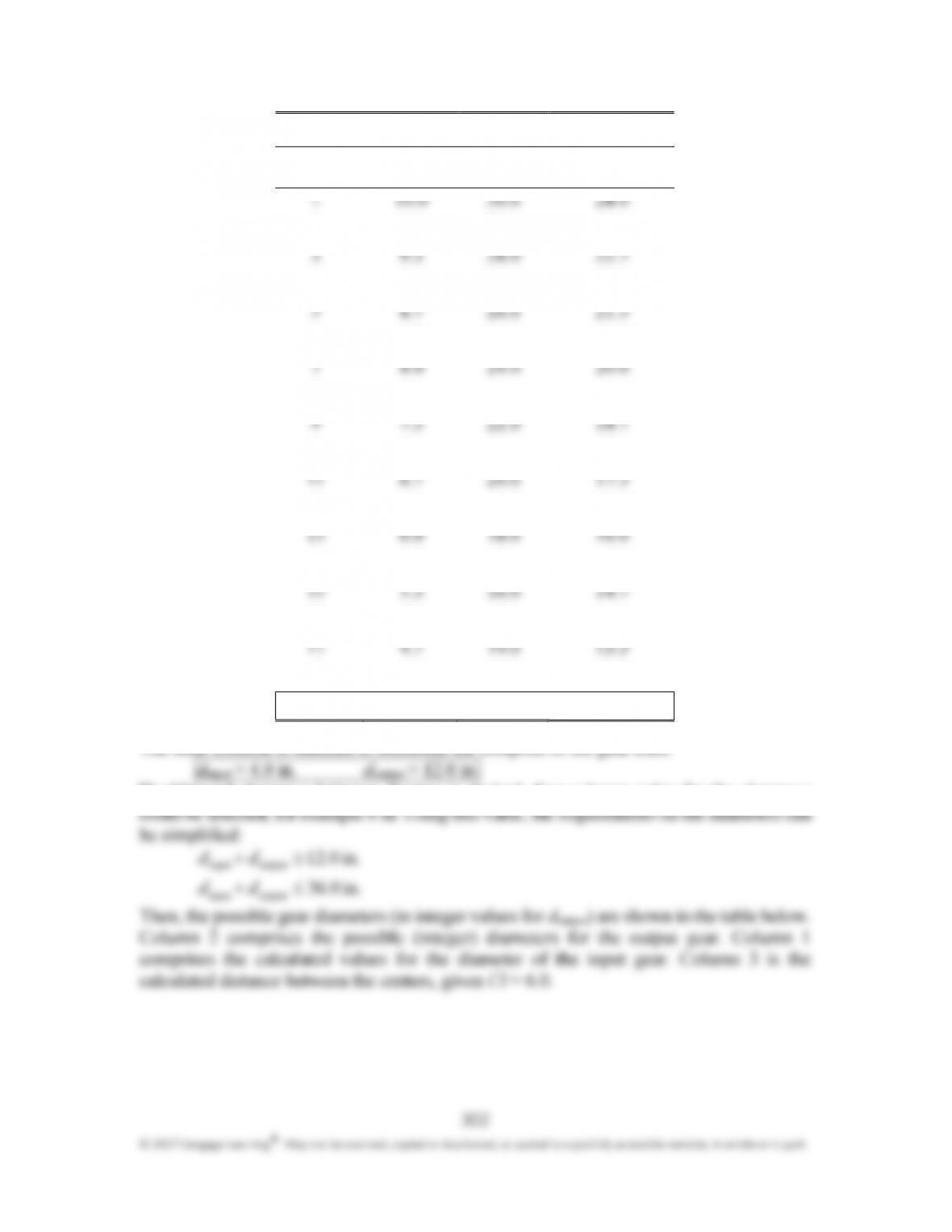
Chapter 8: Motion and Power Transmission
1 2 3
Option dinput (in.) doutput (in.) Distance between
centers
2 9.7 29.0 23.3
4 9.0 27.0 22.0
6 8.3 25.0 20.7
8 7.7 23.0 19.3
10 7.0 21.0 18.0
12 6.3 19.0 16.7
14 5.7 17.0 15.3
16 5.0 15.0 14.0
18 4.3 13.0 12.7
19 4.0 12.0 12.0
The final solution is selected to minimize the footprint of the gear train:
If additional clearance between sheaves is desired, then a larger value for the clearance
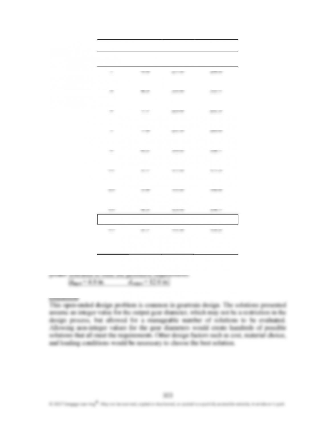
Chapter 8: Motion and Power Transmission
1 2 3
Option dinput (in.) doutput (in.) Distance between
centers
2 8.7 26.0 23.3
4 8.0 24.0 22.0
6 7.3 22.0 20.7
8 6.7 20.0 19.3
10 6.0 18.0 18.0
12 5.3 16.0 16.7
14 4.7 14.0 15.3
16 4.0 12.0 14.0
18 3.3 10.0 12.7
19 3.0 9.0 12.0
With the larger clearance, the same values for the diameters could be selected, allowing for

Chapter 8: Motion and Power Transmission
304