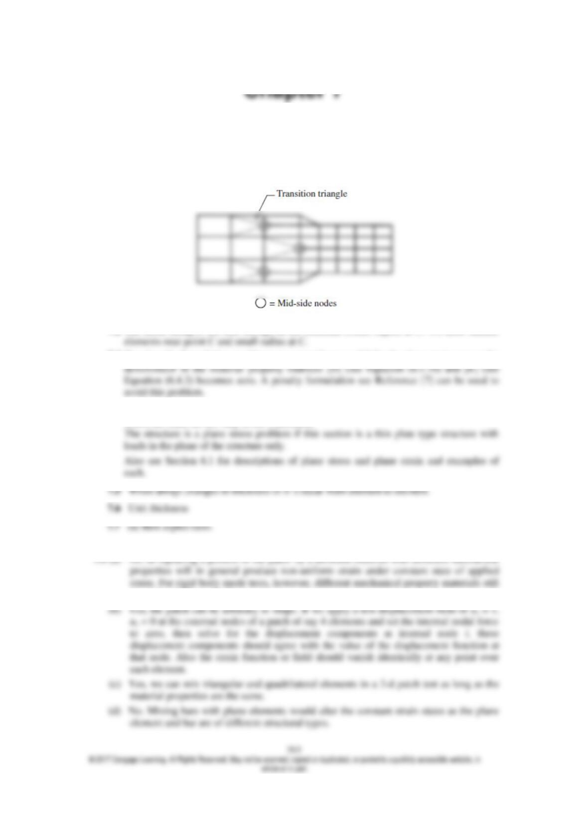
7.1 For the simple 4 noded elements it is a violation of displacement compatibility to have a
mid-side node. Some of the elements have mid-side nodes in this model. Use ‘transition’
triangle to go from smaller to larger rectangular elements.
7.2 The mesh sizing is not fine enough in the reentrant corner region at C. We need smaller
7.3 Based on the formulation used here we cannot have ν = 0.5 for the plane strain case as the
7.4 The structure is plane strain if this section represents a cross section of a long structure in
which the loads do not vary in the z direction.
7.8 See answer to Problem 6.20.
7.9 (a) No, as replacing a portion of the patch by a different material with different mechanical
result in rigid body displacement.
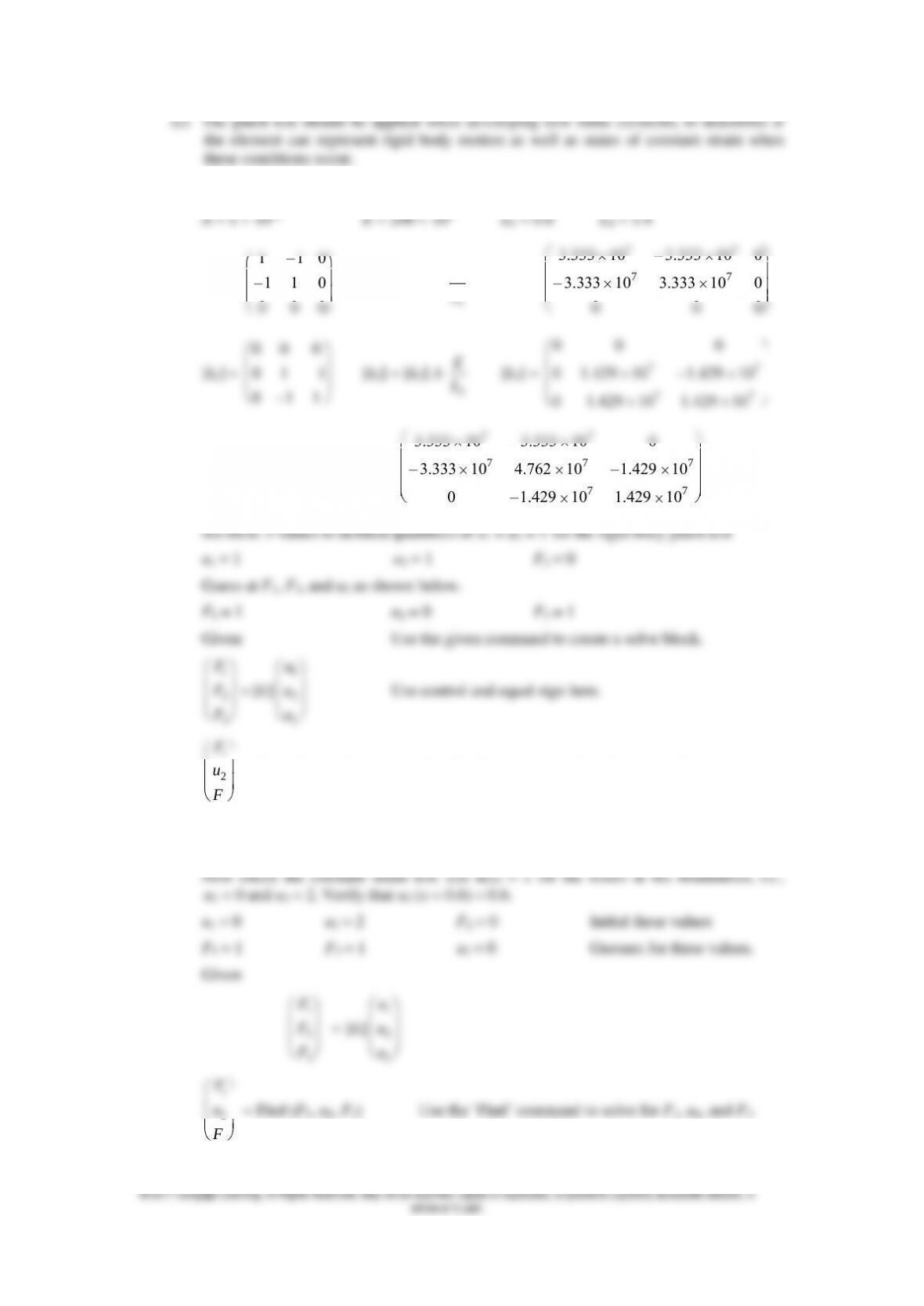
7.10 Using Mathcad
[k1] =
1 –1 0
–1 1 0
0 0 0
[k1] = [k1] A
1
E
L
[k1] =
77
77
3.333 10 – 3.333 10 0
– 3.333 10 3.333 10 0
0 0 0
0 0 0
0 –1 1
2
E
L
77
77
0 0 0
0 –1.429 10 1.429 10
[k] = [k1] + [k2] [k] =
77
7 7 7
77
3.333 10 – 3.333 10 0
– 3.333 10 4.762 10 –1.429 10
0 –1.429 10 1.429 10
22
33
Fu
1
2
3
F
u
F
= Find (F1, u2, F3) Use the ‘Find’ command to find F1, u2, and F3.
F1 = 0 u2 = 1 F3 = 0
The rigid body motion patch test is satisfied as u2 = 1.
365
F1 = – 2 107 F3 = 2 107 u2 = 0.6
Now upon solving the system of equations u2 = 0.6 as it should to satisfy the patch test
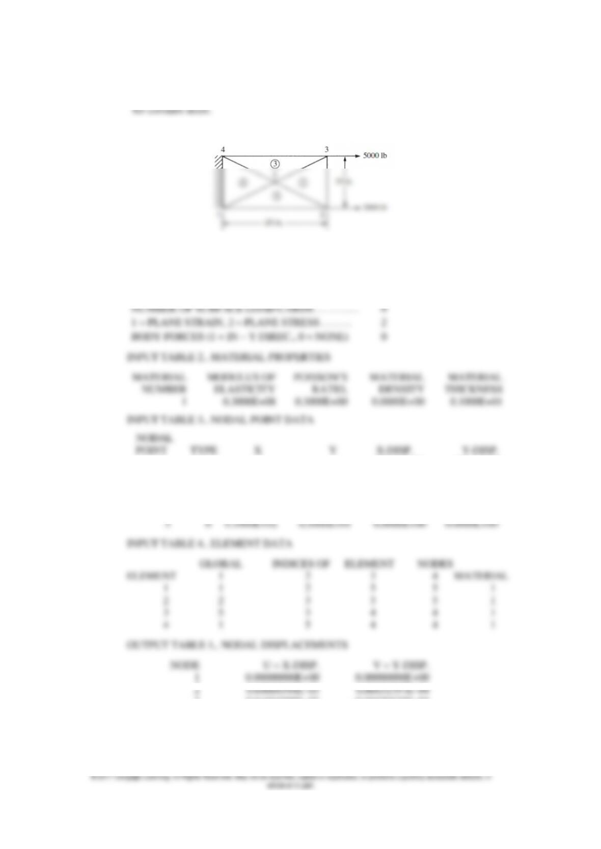
7.12
INPUT TABLE 1.. BASIC PARAMETERS
NUMBER OF NODAL POINTS. . . . . . . . . . . . . . . 5
NUMBER OF ELEMENTS. . . . . . . . . . . . . . . . . . . 4
NUMBER OF DIFFERENT MATERIALS. . . . . . . 1
OR LOAD OR LOAD
1 3 0.0000E+00 0.0000E+00 0.0000E+00 0.0000E+00
2 0 0.2000E+02 0.0000E+00 0.5000E+04 0.0000E+00
3 0 0.2000E+02 0.1000E+02 0.5000E+04 0.0000E+00
4 3 0.0000E+00 0.1000E+02 0.0000E+00 0.0000E+00
3 0.61664509E–03 –0.66630528E–04
4 0.00000000E+00 0.000000000E+00
5 0.30527671E–03 0.24373945E–09
OUTPUT TABLE 2.. STRESSES AT ELEMENT CENTROIDS
366
ELEMENT X Y SIGMA(X) SIGMA(Y) TAU(X, Y)
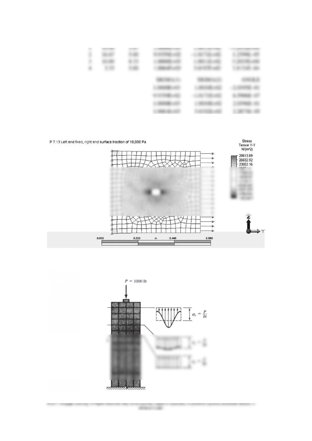
7.13
7.14
367
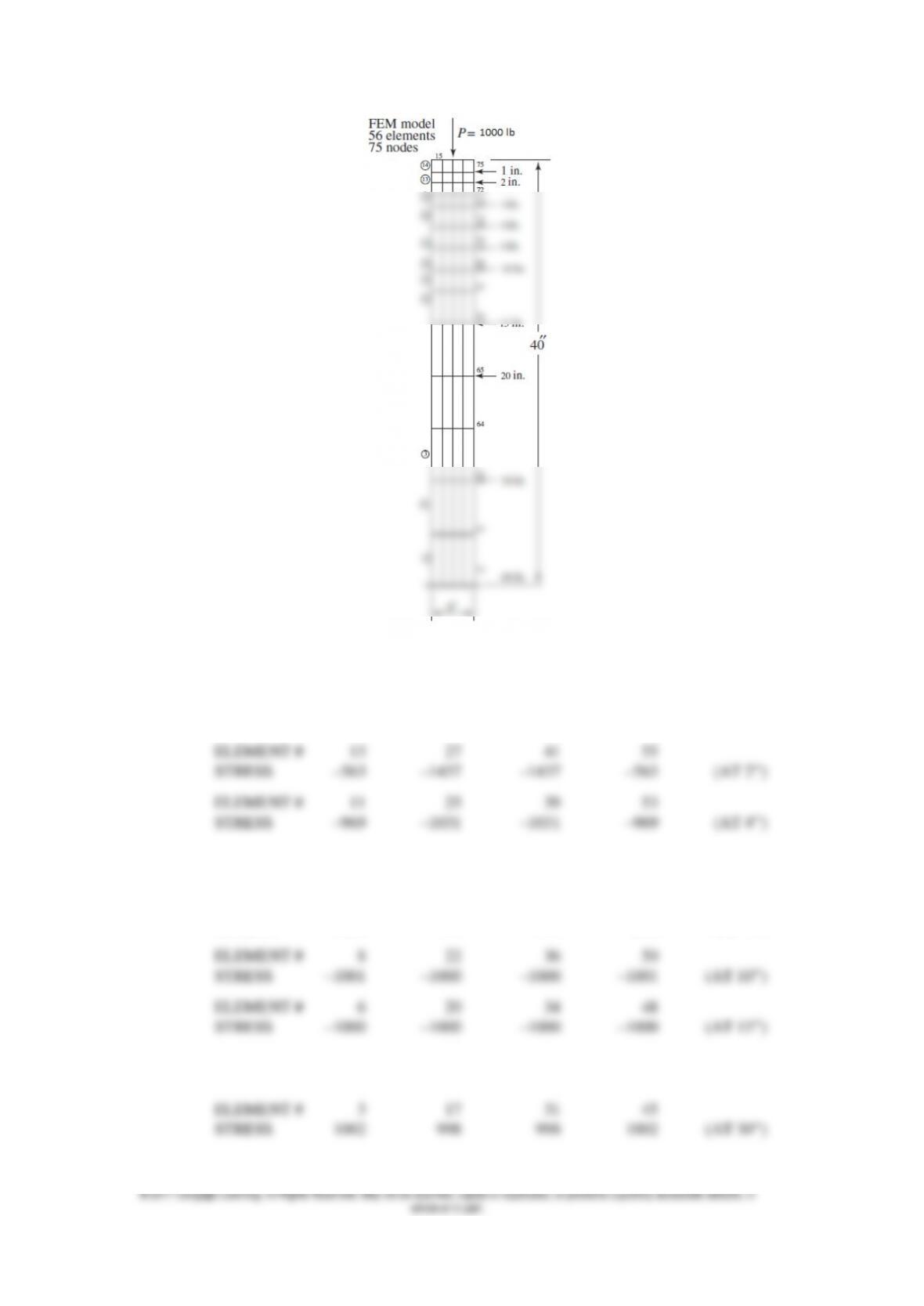
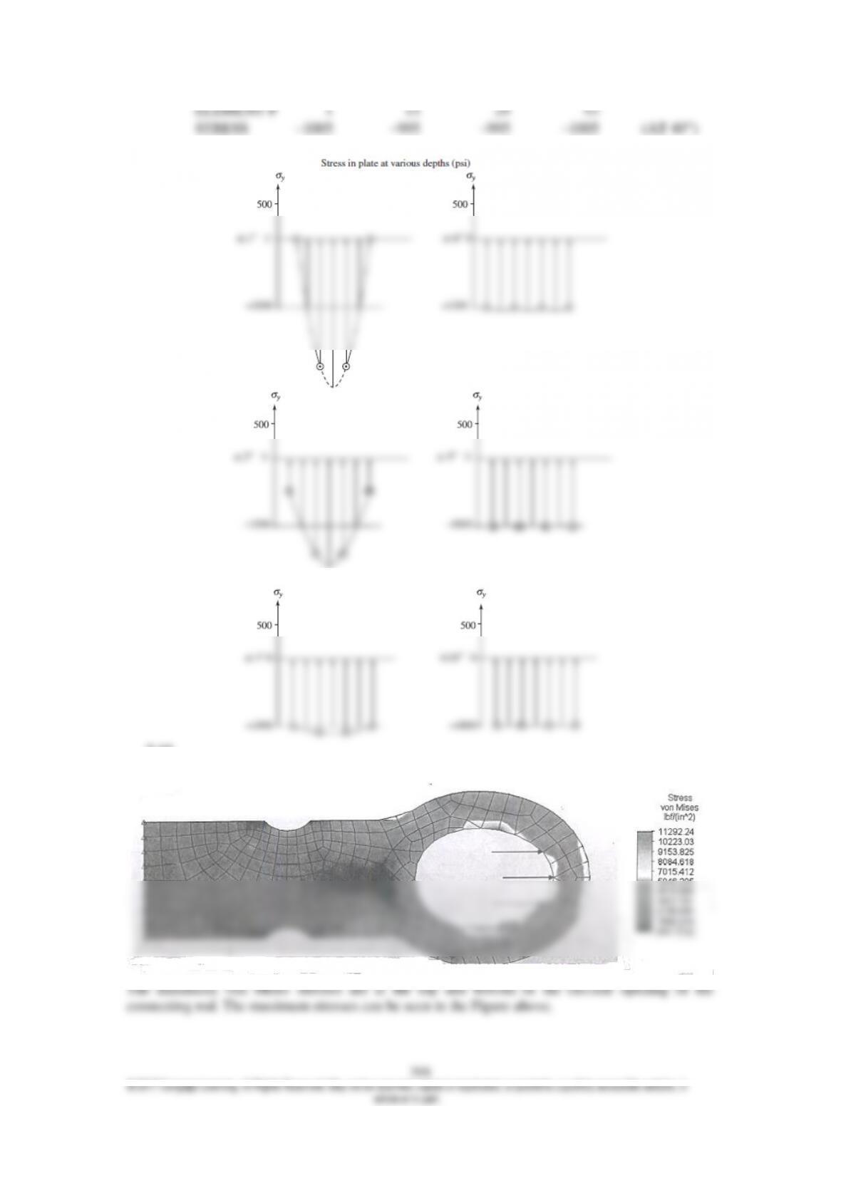
STRESS IN PSI AT VARIOUS DISTANCES
ALONG THE TENSILE PLATE WITH A 1000 # LOAD
ELEMENT # 14 28 42 56
STRESS 26 –2026 –2026 26 (AT 1)
ELEMENT # 10 24 38 52
STRESS –1002 –998 –998 –1002 (AT 6)
ELEMENT # 9 23 37 51
STRESS –1002 –998 –998 –1002 (AT 8)
ELEMENT # 5 21 33 47
STRESS –1000 –1000 –1000 –1000 (AT 20)
7.15
369
7.16
7.17
370
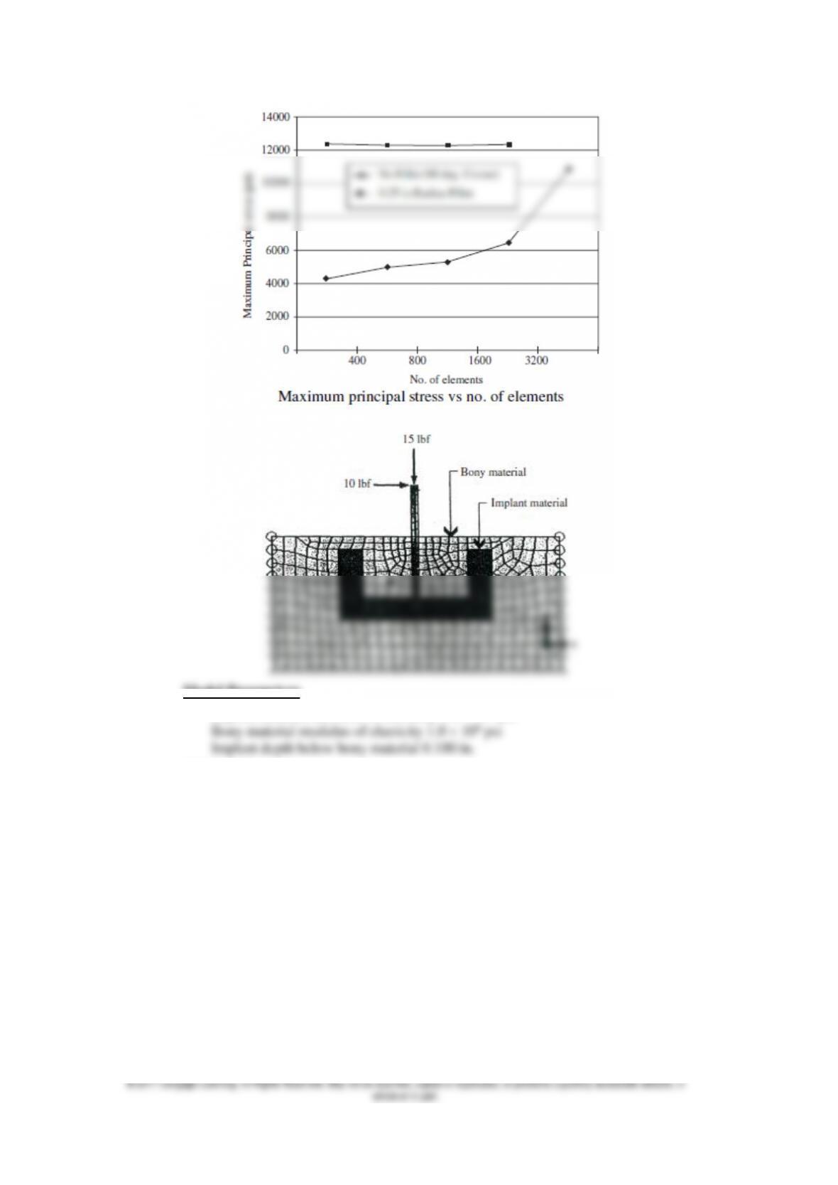
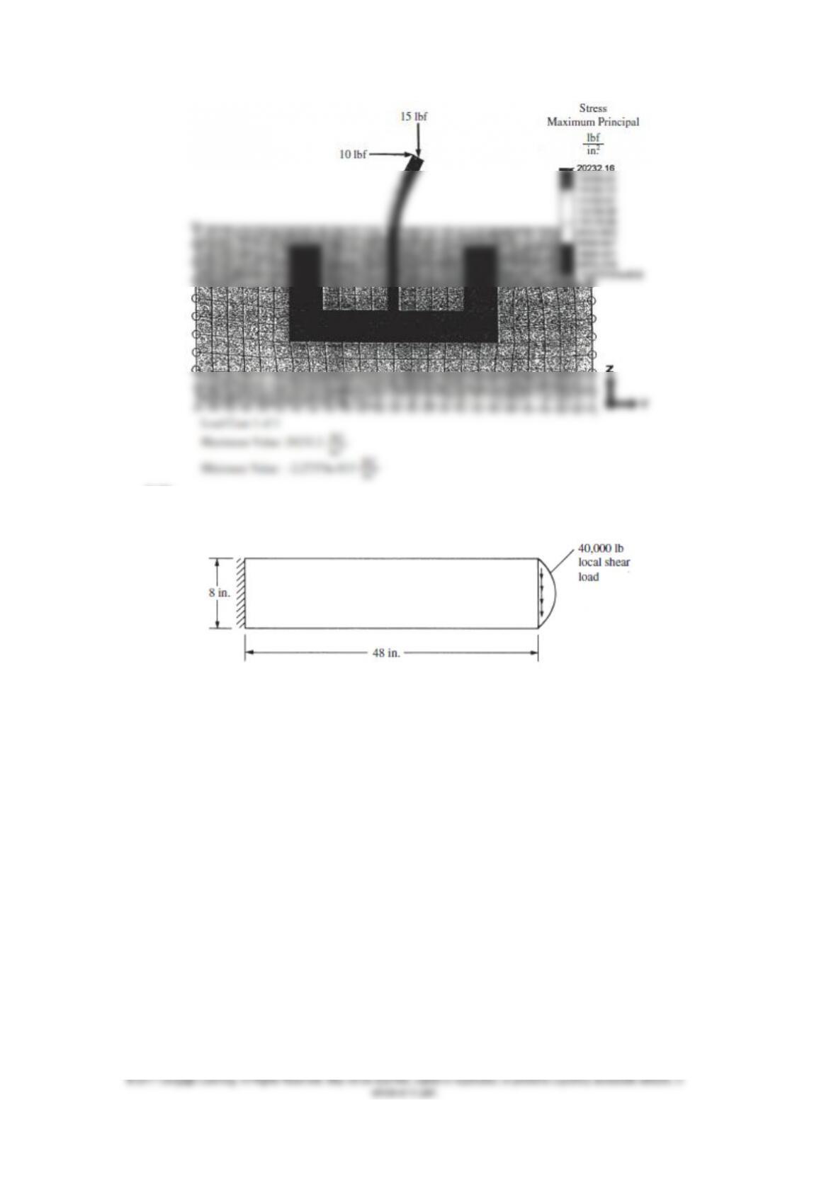
7.19
Model Parameters
Implant material modulus of elasticity 1.6 106 psi
400 Mesh Density
371
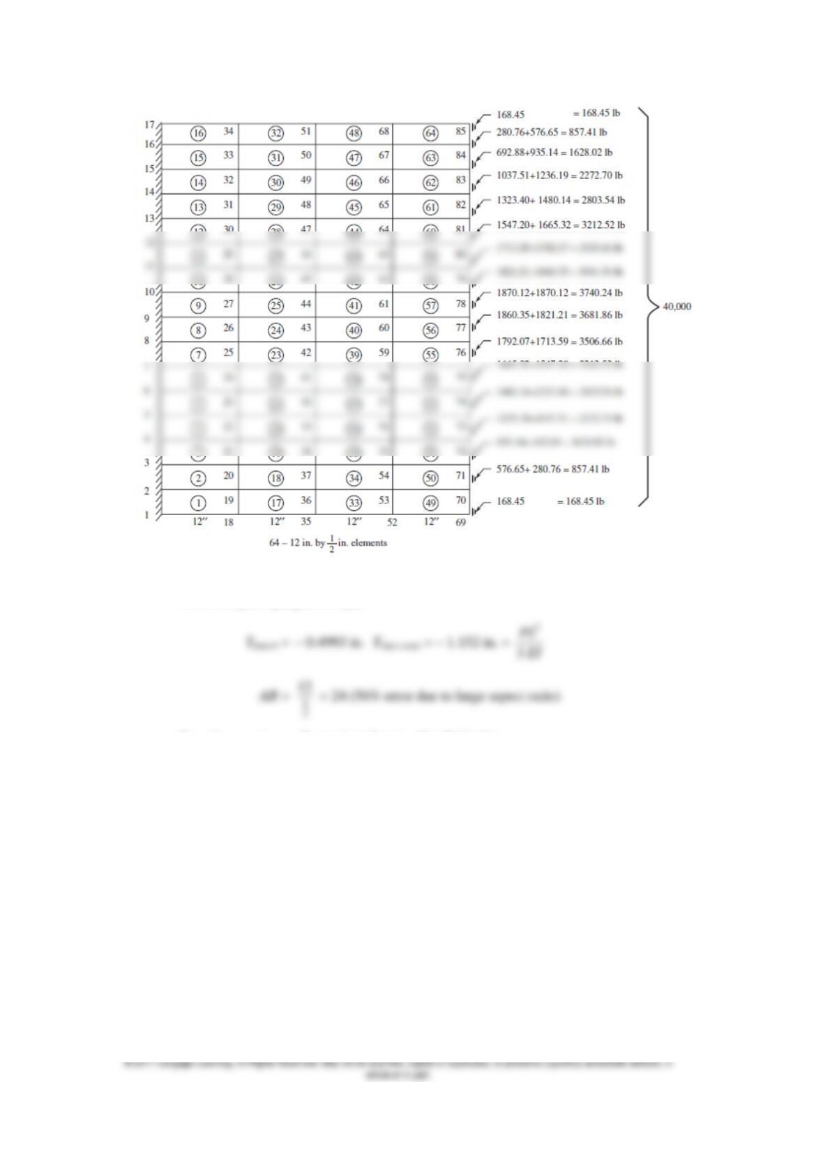
7.20
372
From computer program output
3
PL
1
2
For other results see Example in Section 7.1, Table 7.1
373
7.21
7.22
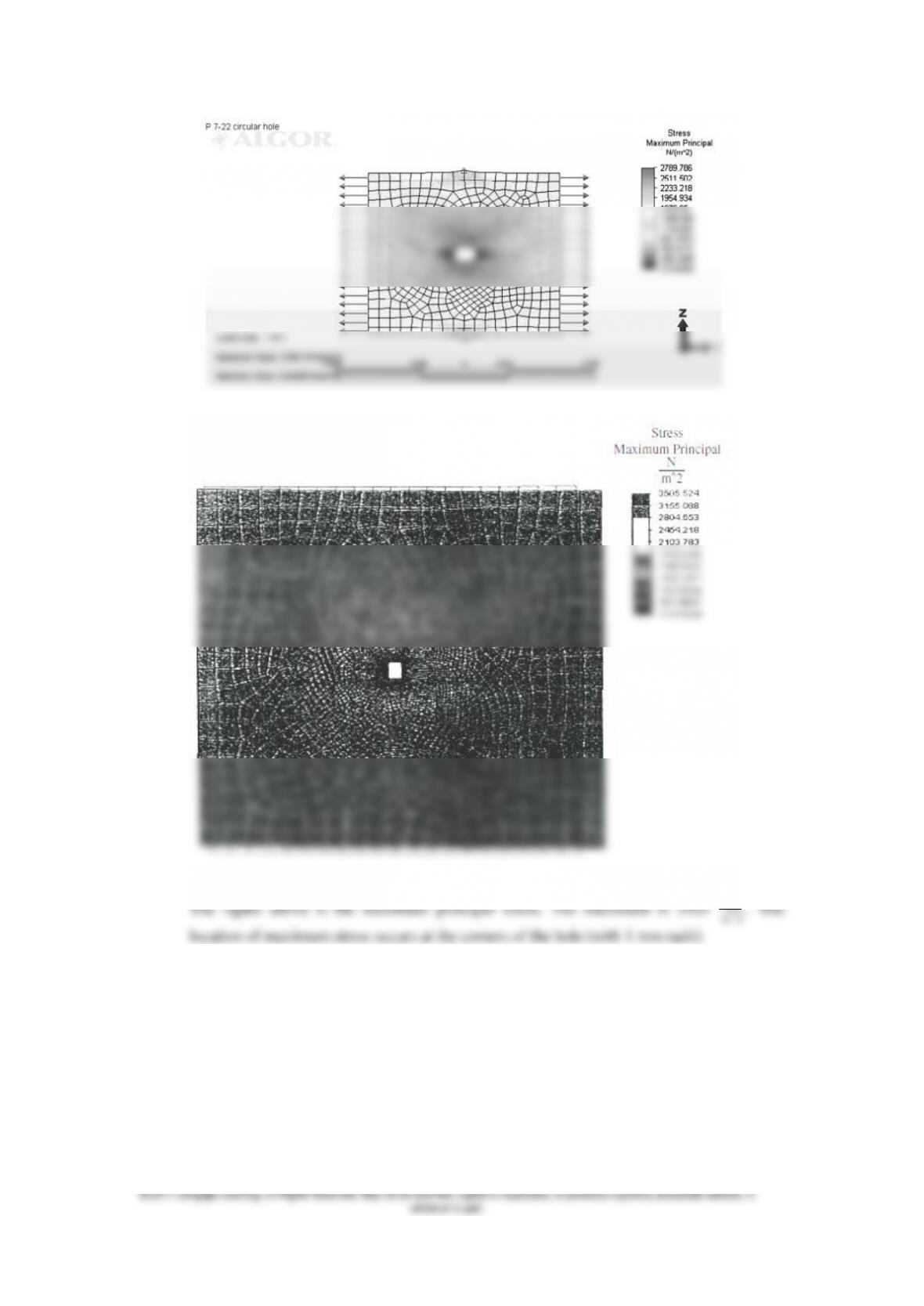
375
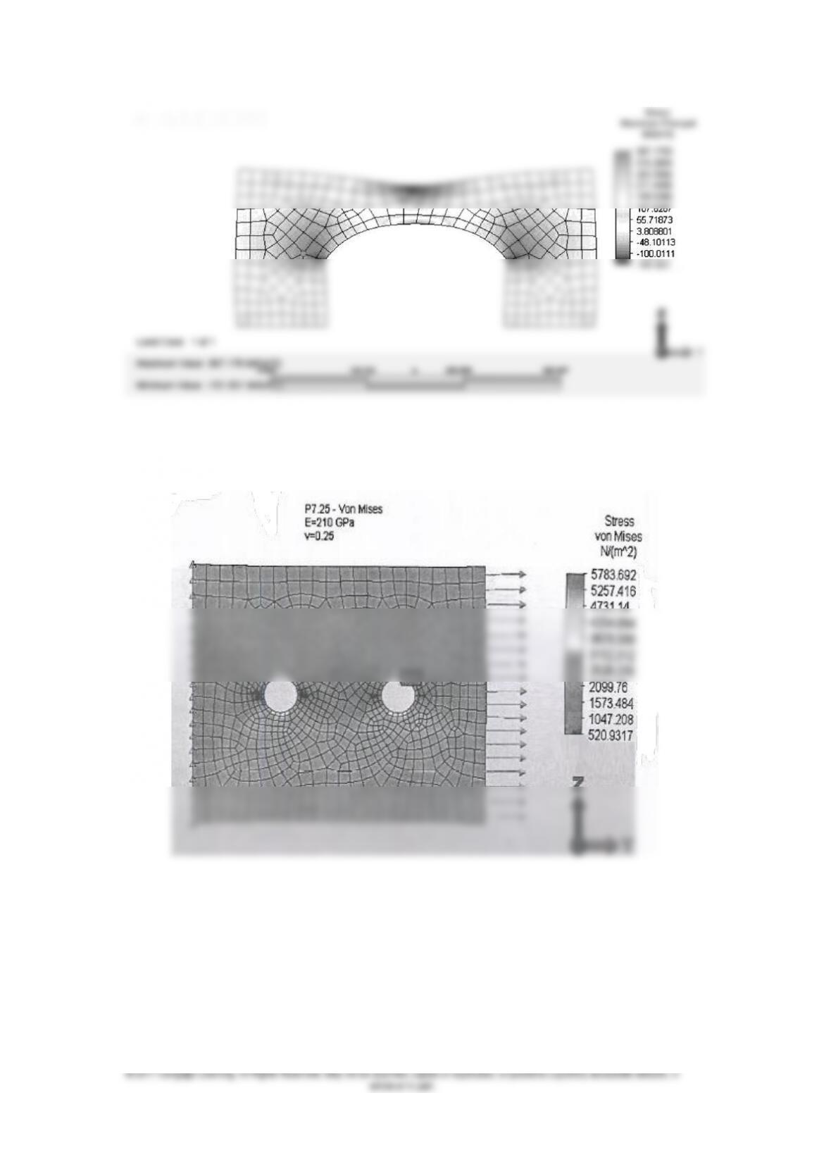
7.25
7.26
376
7.28
377
7.31

378
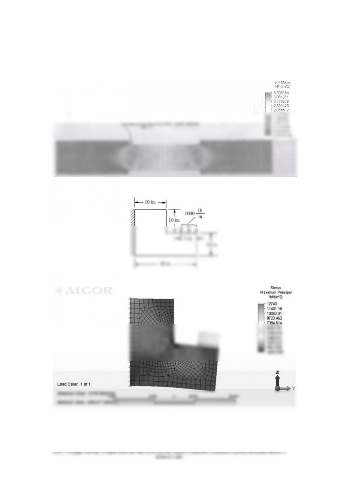
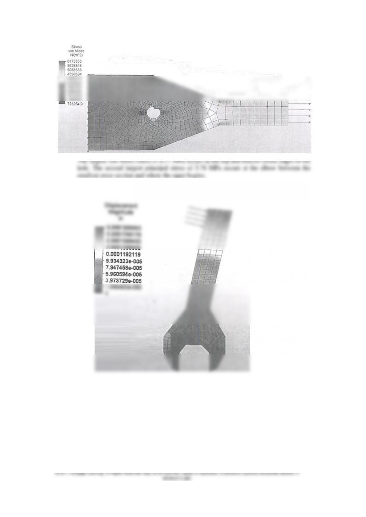
Loads and Constraints:
Fixed at bottom half of hole
Concentrated load of 5000 lbf
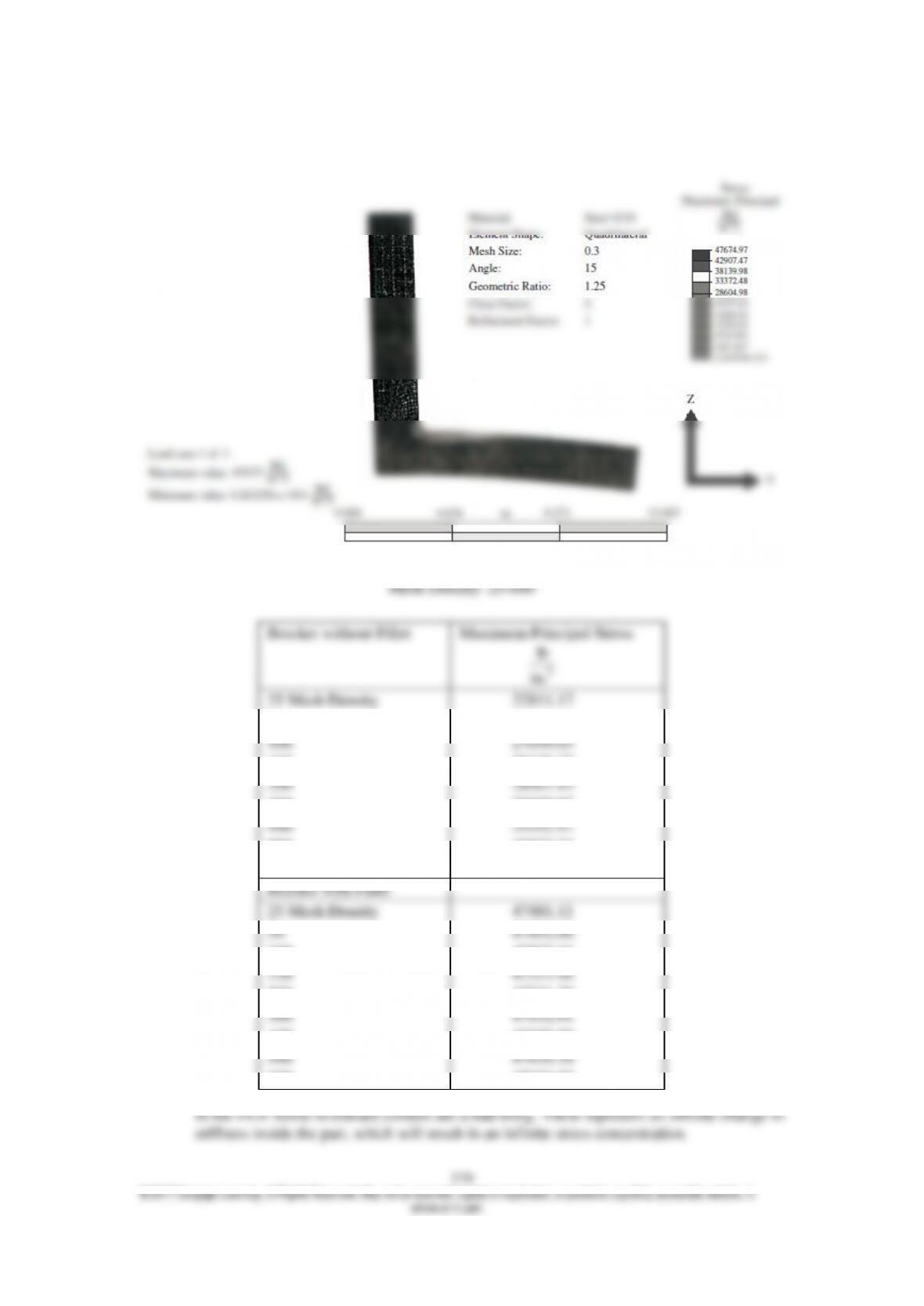
7.32
600 Mesh Density
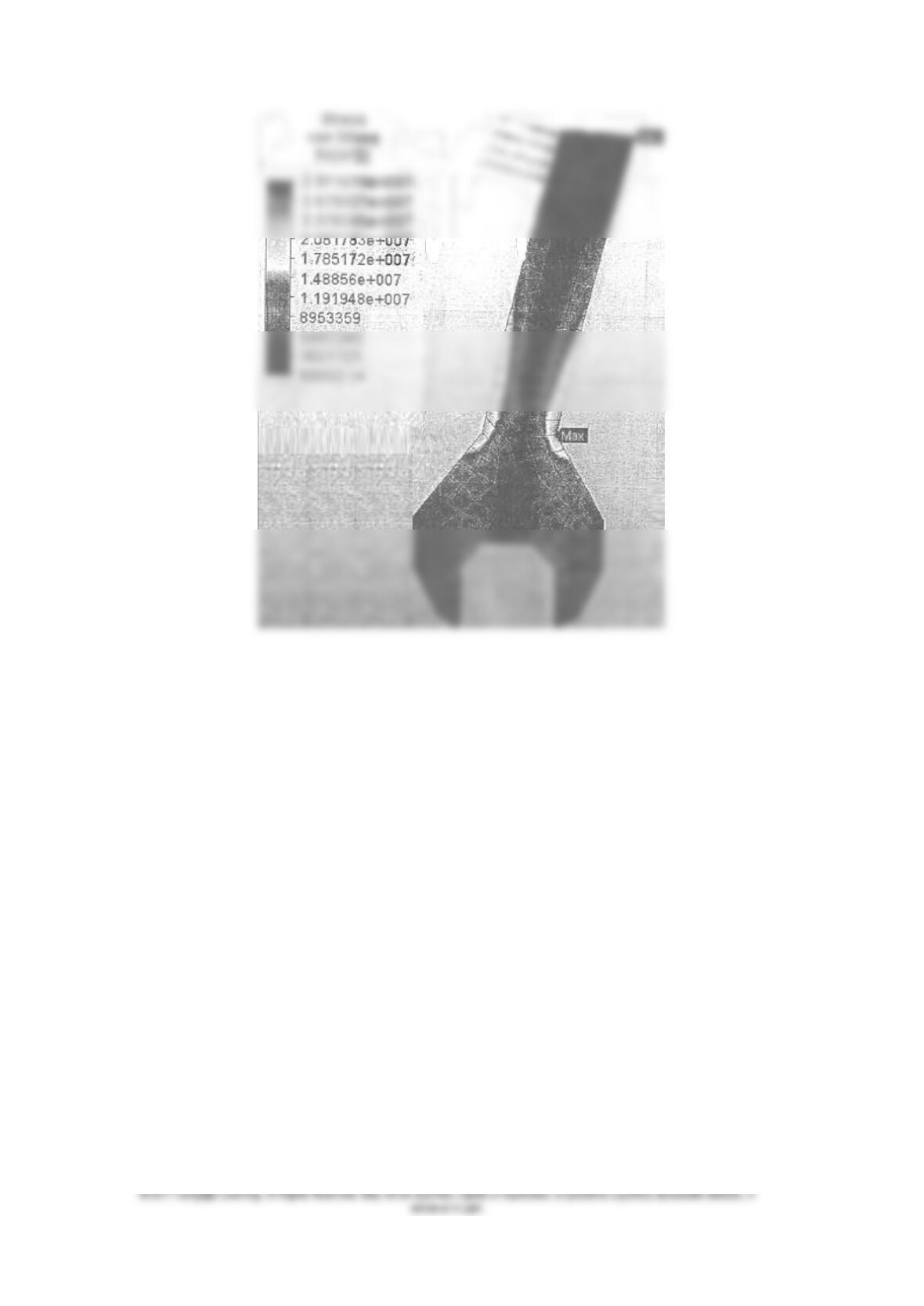
7.33
7.37
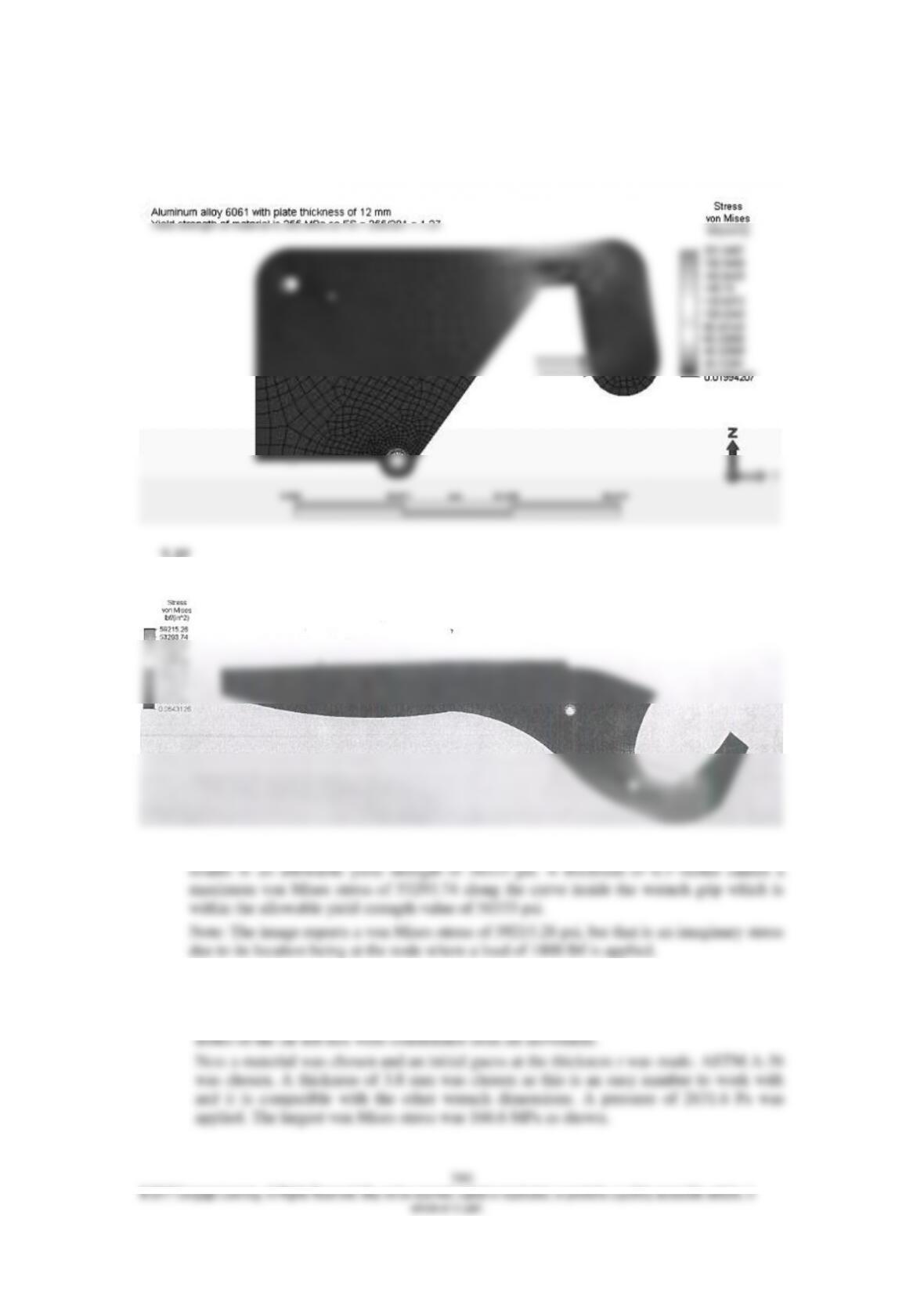
1080 as-rolled steel has a yield strength for 84800 psi. Dividing by a factor of safety of 1.5
7.38
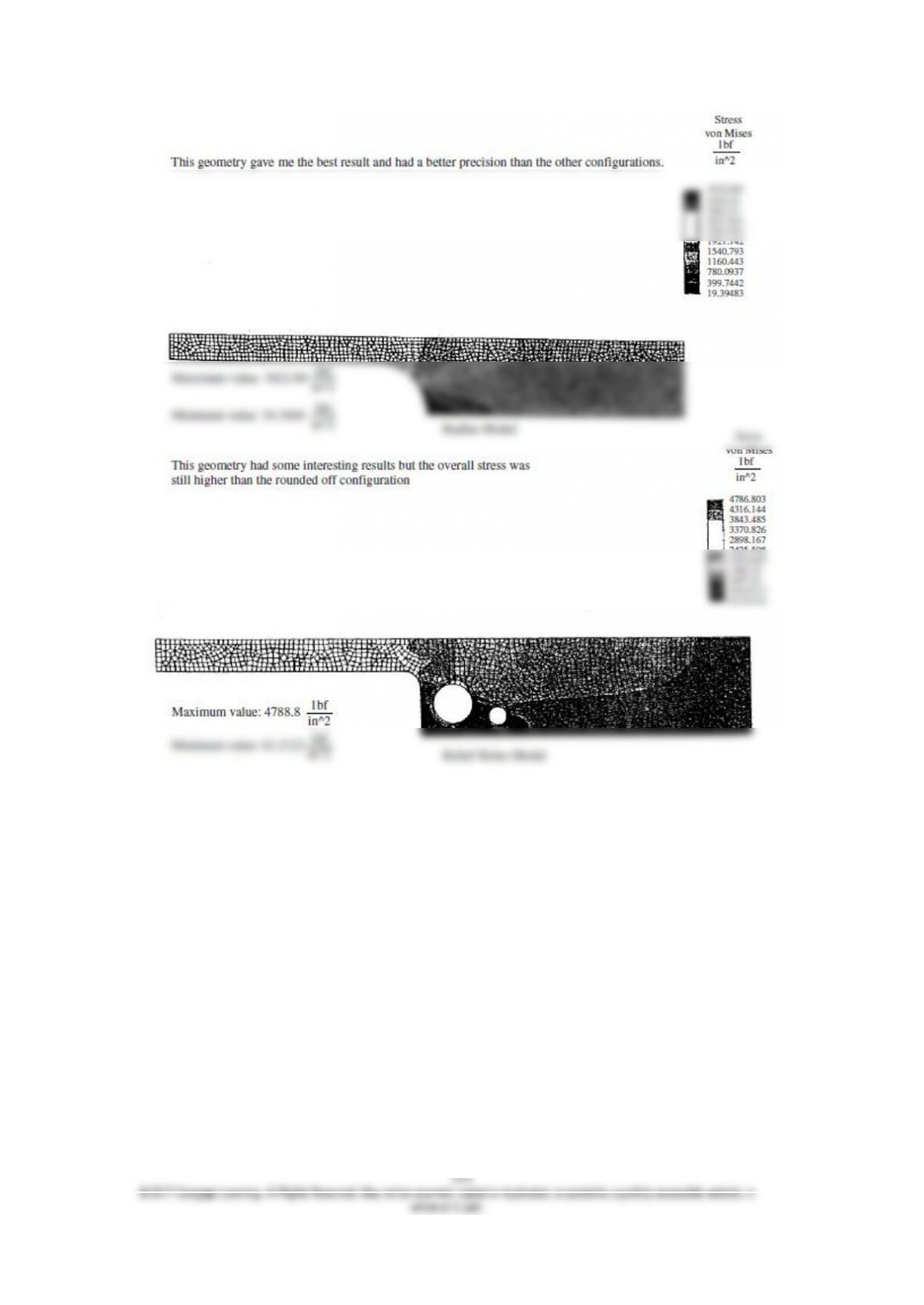
The model is shown first with the boundary and loading conditions then applied. The
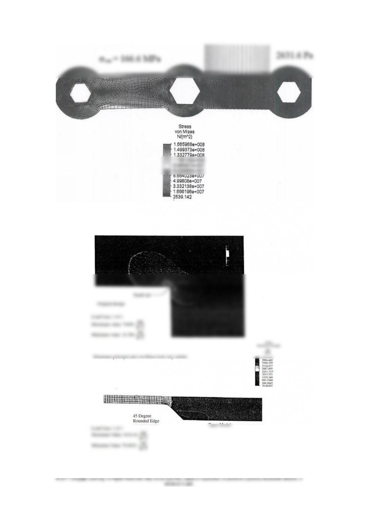
381
7.39 Zoomed in of the previous. To simulate a real cut, I inserted a very small radius at
the point of concern.