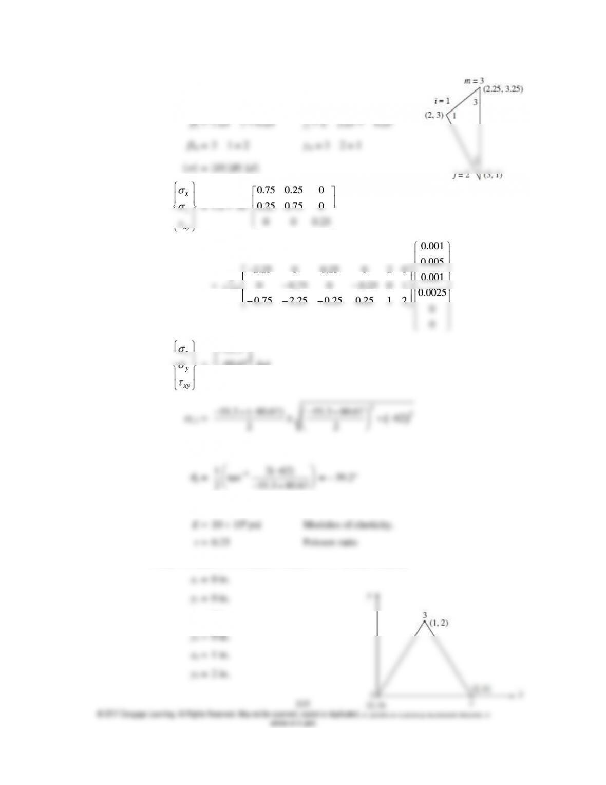
= 0.375 in.2
i = 1 – 3.25 = – 2.25
i = 2.25 – 3 = – 0.75
x
y
xy
0 0 0.25
0.001
0.005
2.25 0 0.25 0 2 0 0.001
10 0.75 0 0.25 0 1 0.0025
0.75 0.75 2.25 0.25 0.25 1 2 0
0
x
y
xy
=
55.3
80.67
62
ksi
22
55.3 ( 80.67) 55.3 80.67 62
22
1 = – 4.73 ksi
2 = – 131.3 ksi
1
1 2( 62)
2 55.3 80.67
(f) Material properties
Nodal coordinates (coordinates defined CCW around element)
x2 = 2 in.
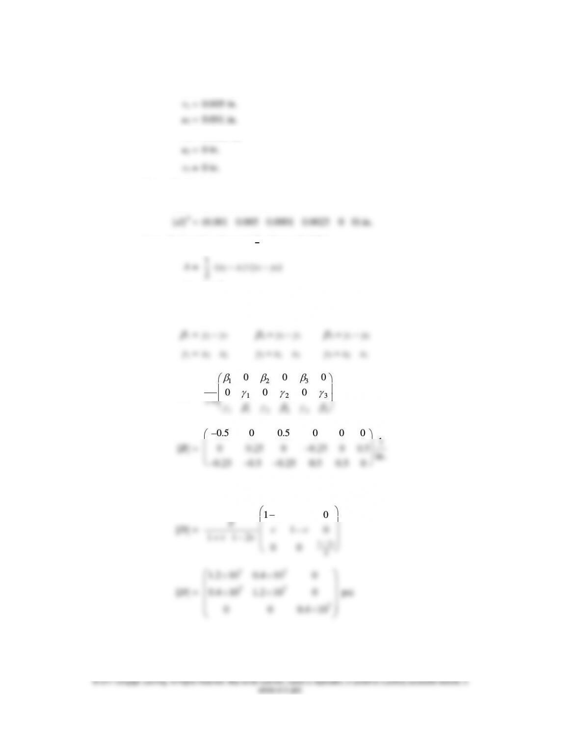
Nodal displacements
u1 = 0.001 in.
v2 = 0.0025 in.
Set-up displacement vector
{d} = (u1 v1 u2 v2 u3 v3)T
Area of triangular element (
1
2
base height)
1
2
A = 2 in.2
Calculate gradient matrix, B, as given in text Equation (6.2.32)
Elements of B given by text Equation (6.2.10).
[B] =
1 2 3
1 2 3
1 1 2 2 3 3
0 0 0
10 0 0
2A
0.5 0 0.5 0 0 0 1
0.25 0.5 0.25 0.5 0.5 0
Calculate constitutive matrix for plane strain
10
vv
Evv
x
y
xy
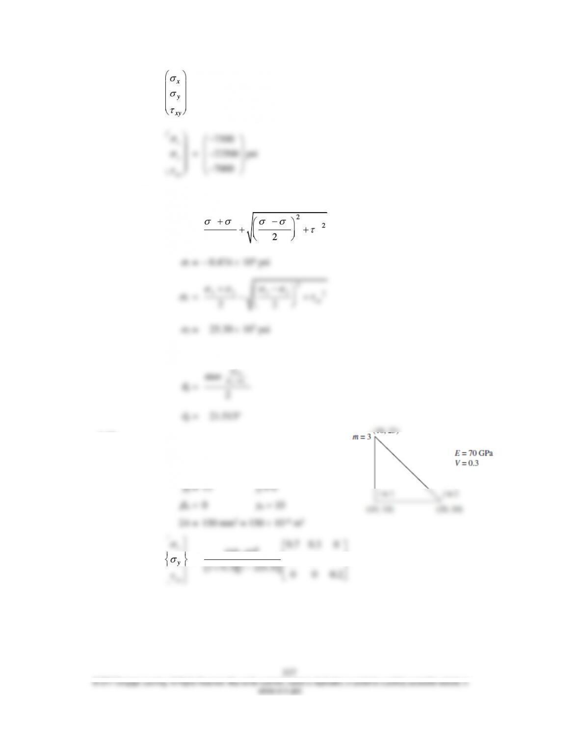
= [D]B] {d}
x
y
xy
7500
7000
Principal stresses
1 =
2
2
22
x y x y
xy
Angular location of principal stress plane
2
atan
xy
xy
6.10
(a)
i = – 15
i = – 10
x
y
xy
=
60.7 0.3 0
105 10 0.3 0.7 0
1 0.3 1 2(0.3) 0 0 0.2
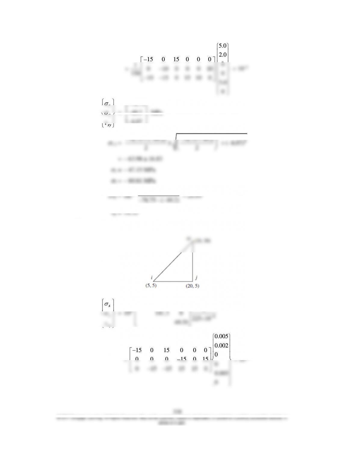
x
5.0
2.0
15 0 15 0 0 0 0
10 10 0 0 0 10 0
150 10 15 0 15 10 0 5.0
0
x
78.75
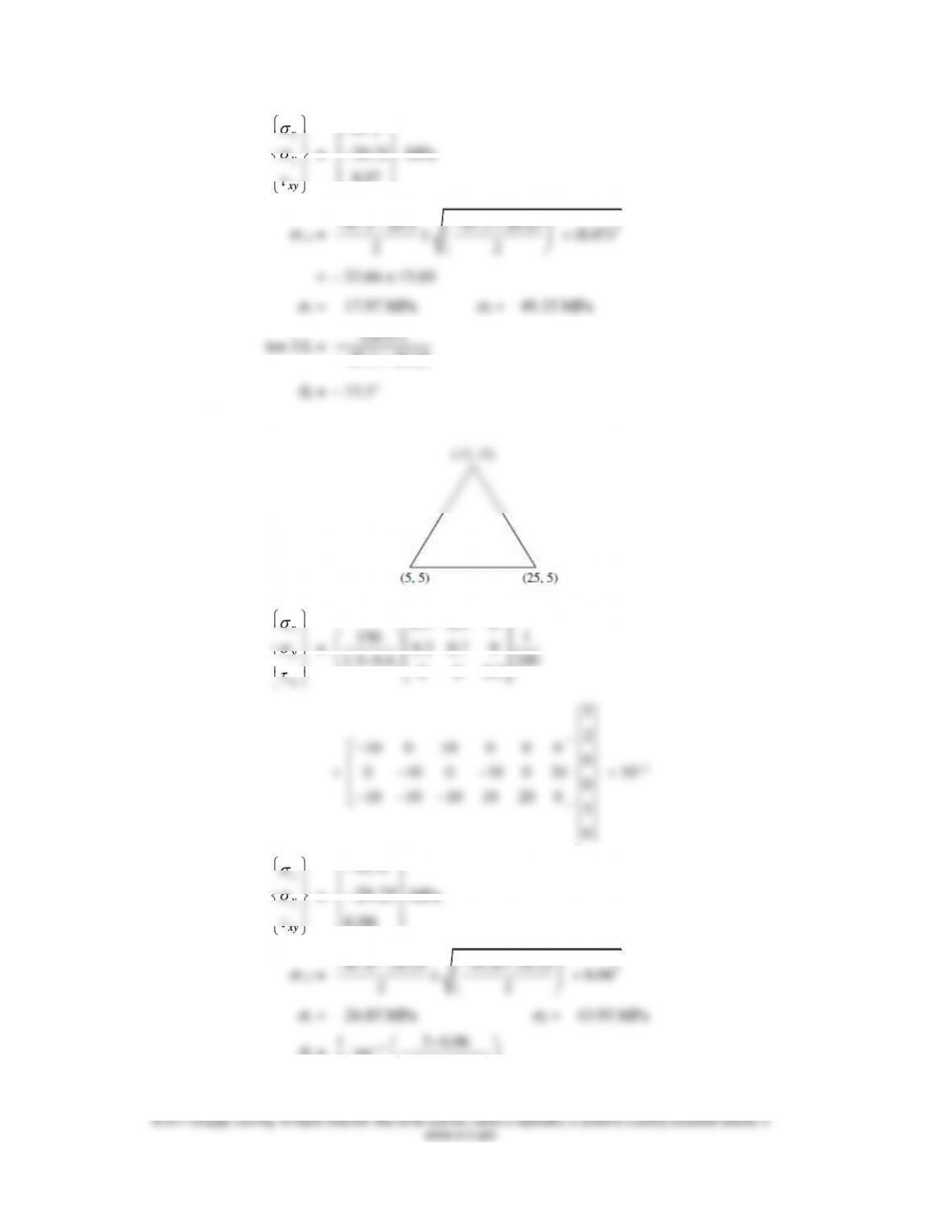
x
47.1
x
x
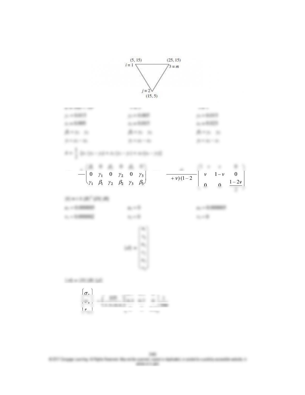
p = – 22.5°
(d)
2
[B] =
1 2 3
123
1 1 2 2 3 3
0 0 0
10 0 0
2A
[D] =
1 – 0
10
(1 ) (1 – 2 ) 1 – 2
00 2
vv
Evv
vv v
x
y
xy
=
0.7 0.3 0
105 1
0.3 0.7 0
1.3 0.4 200
0 0 0.2
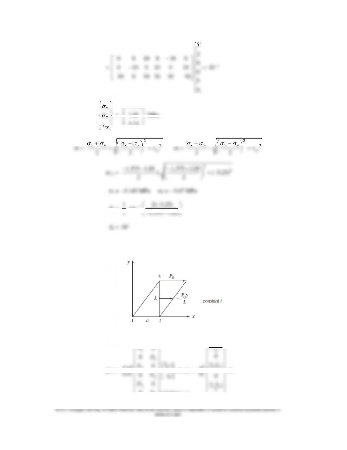
5
2
0 0 10 0 10 0 0
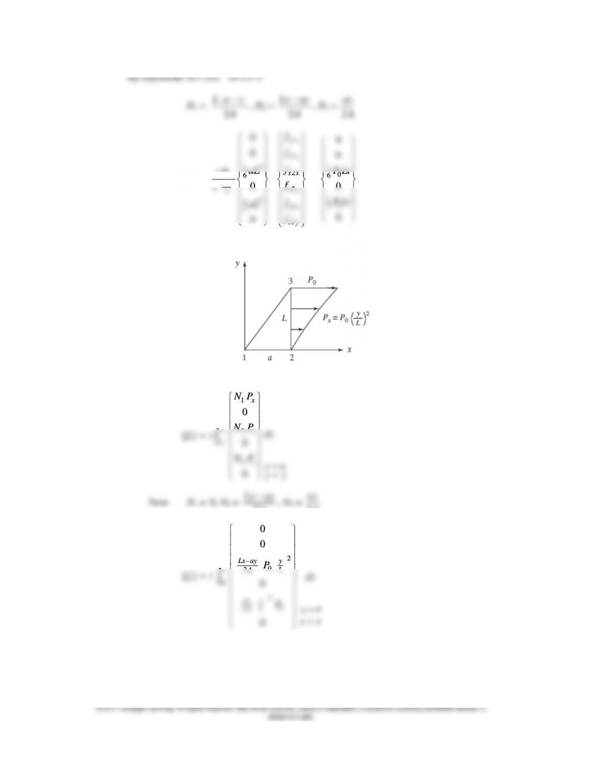
2
A
2
A
2
A
2
A
{fs} =
2
1
06
2
2
1
3
0
0
0
2
0
aL
aL
tP
aL
,
1
1
2
2
3
3
sx
sy
sx
sy
sx
sy
f
f
f
f
f
f
=
10
6
10
3
0
0
0
0
P Lt
P Lt
(b)
By Equation (6.3.11)
L
1
2
0
x
x
NP
NP dy
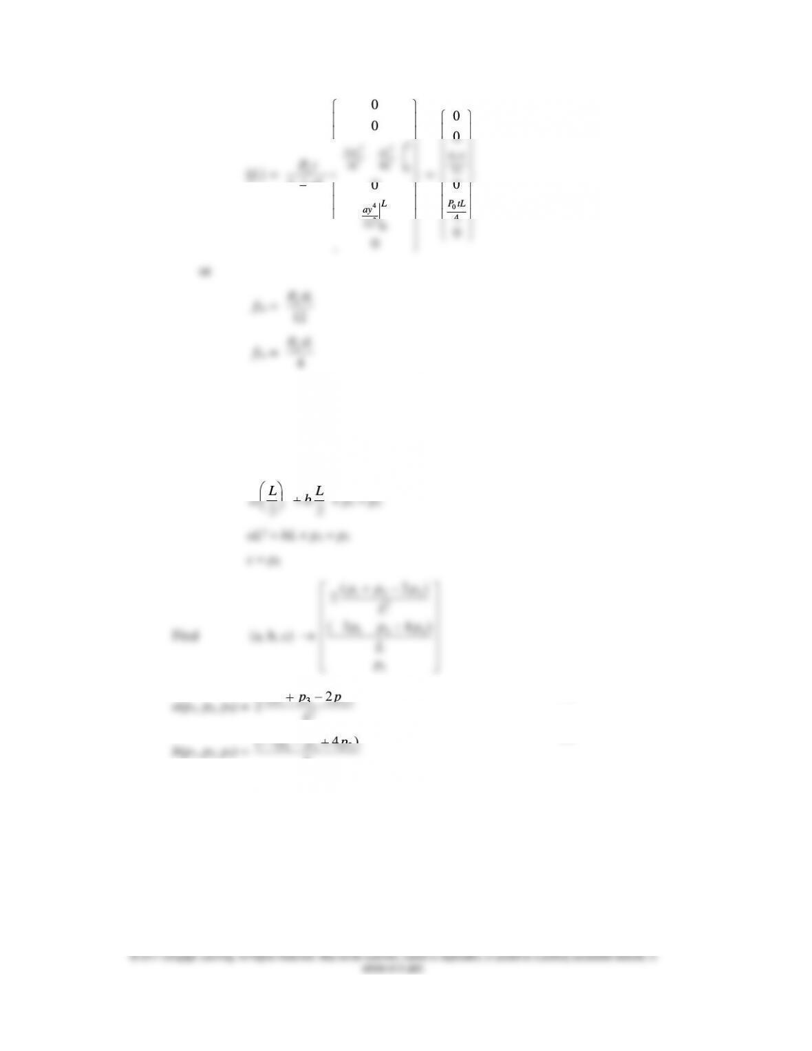
34
22
34
0
0
0
0
L
Lay ay
LL
Pt
0
12
0
0
P tL
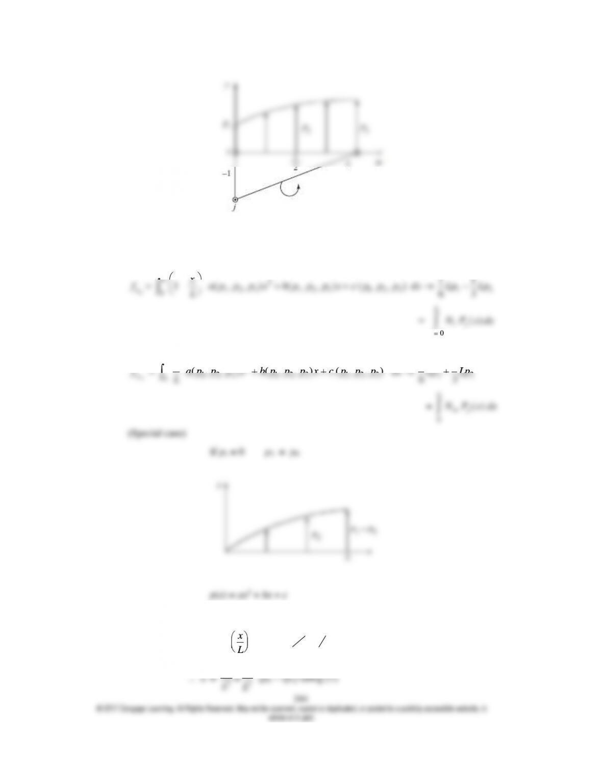
Forces in y direction at nodes 1 and 3 are
N1 = Ni
2
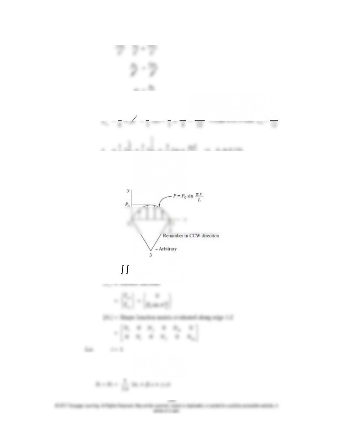
Lxa p p p x b p p p x c p p p
11
1
0
0
2p
0
p
2
4p
2
L
2
L
p2 =
0
4
p
Then
1
0
1
1
0
p
0
pL
pL
1
2A
1
2A
2
A
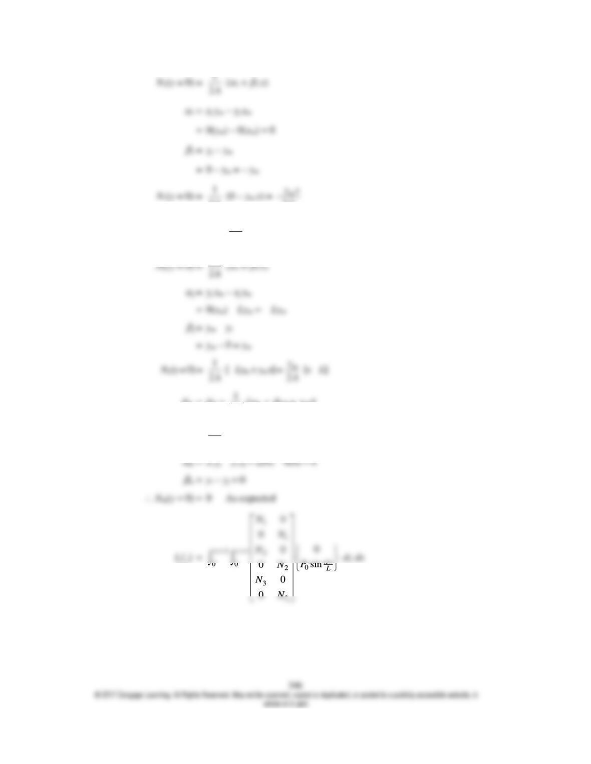
Nj = N2 =
1
2A
(
j +
j x +
j y)
1
2A
2A
2
A
Nm = N3 =
1
2A
[
m +
mx +
my]
N3(y = 0) =
1
2A
[
m +
mx]
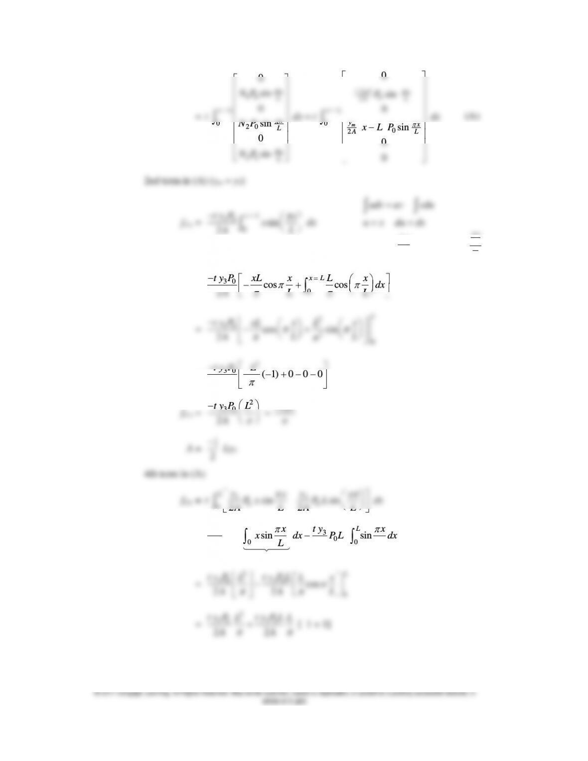
10
0
sin
0
x
L
xL
NP
0
2
0
sin
0
m
yx x
AL
xL
P
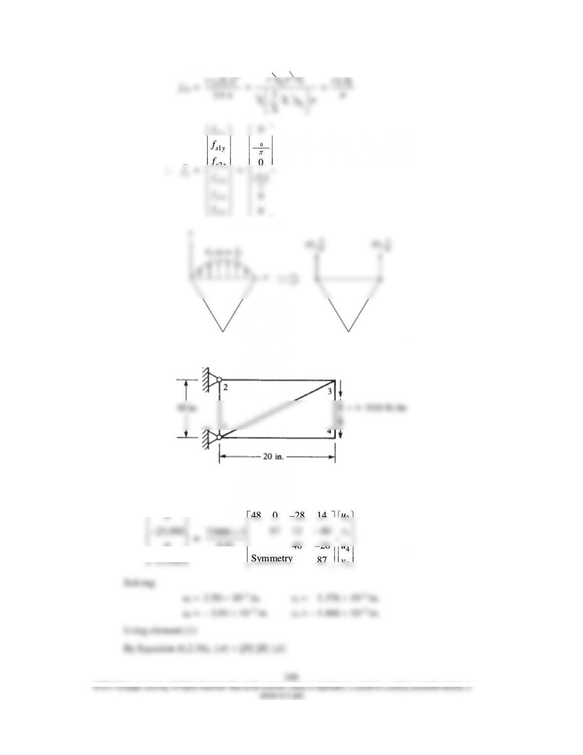
2
30
t y P L
3
ty 2
L0
P
0
t L P