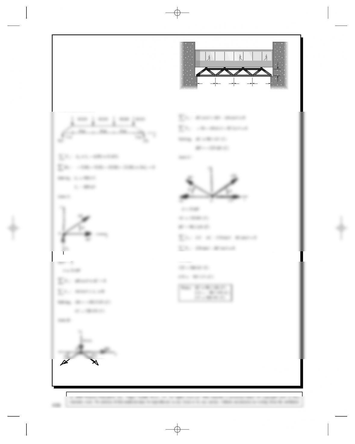
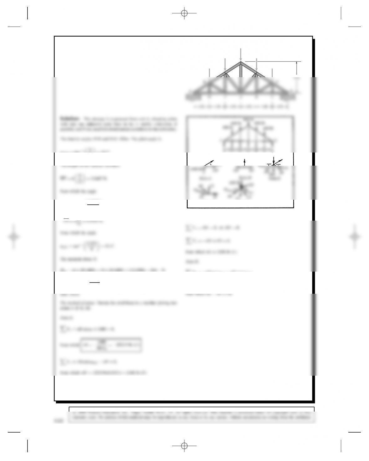
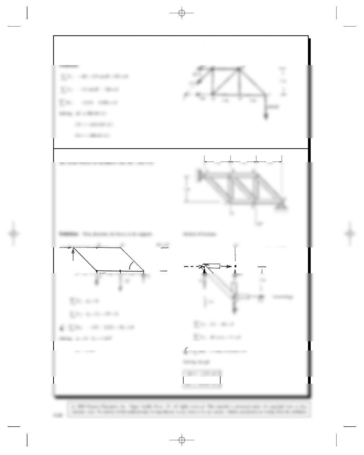
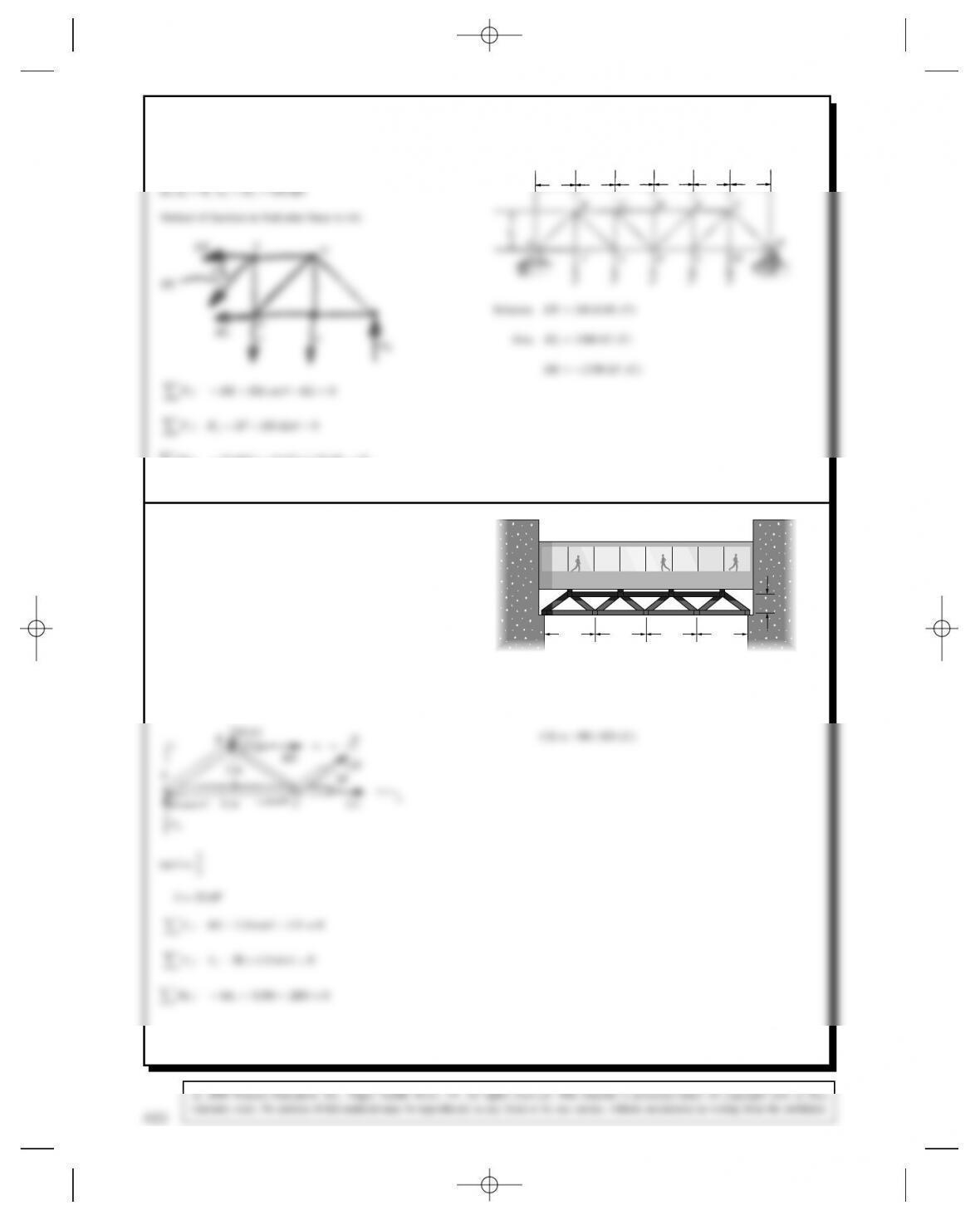
Problem 6.22 The Warren truss supporting the
walkway is designed to support vertical 50-kN loads at
B,D,F, and H. If the truss is subjected to these loads,
what are the resulting axial forces in members BC,CD,
and CE?
6 m6 m6 m6 m
ACEGI
BDFH
2 m
Solution: Assume vertical loads at Aand IFind the external loads
at Aand I, then use the method of joints to work through the structure
to the members needed.
AB D180.3kN
D33.69°
406
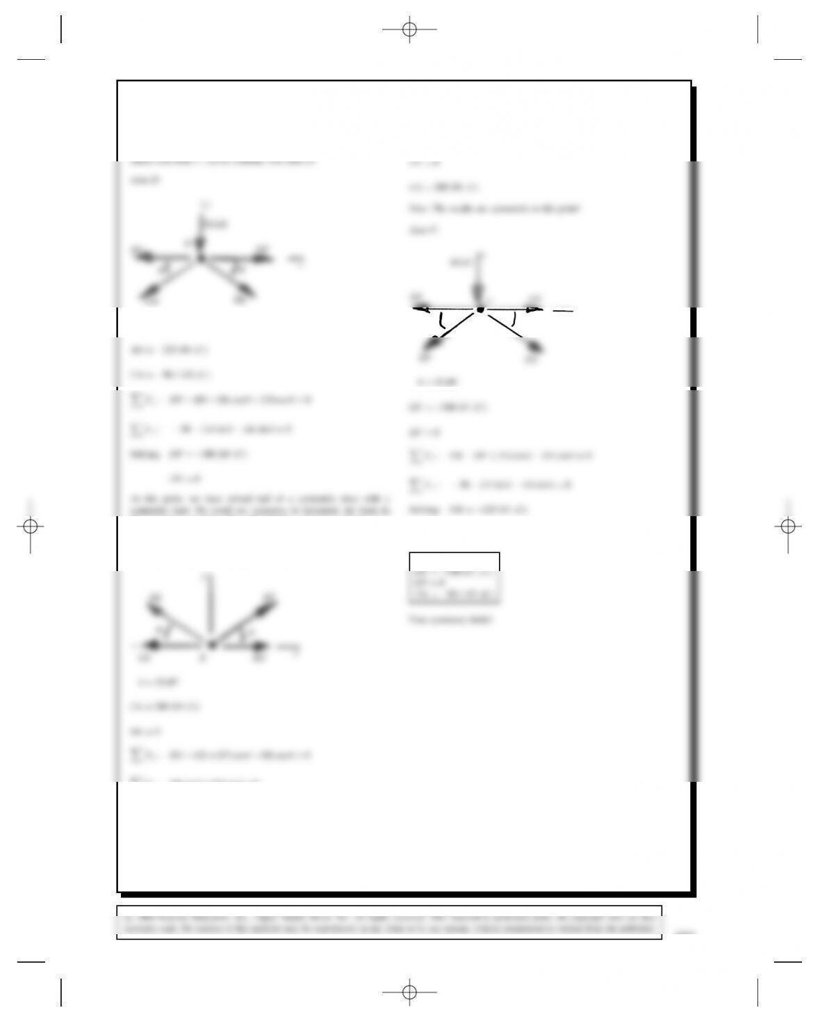
Problem 6.23 For the Warren truss in Problem 6.22,
determine the axial forces in members DF,EF, and FG.
Solution: In the solution to Problem 6.22, we solved for the forces
in AB,AC,BC,BD,CD, and CE. Let us continue the process. We
CD DE
D33.69°
the remaining members. We will continue, and use symmetry as a
check.
Joint E :
Solving, we get
x
θθ
FG D90.1kN⊲C⊳
Thus, we have
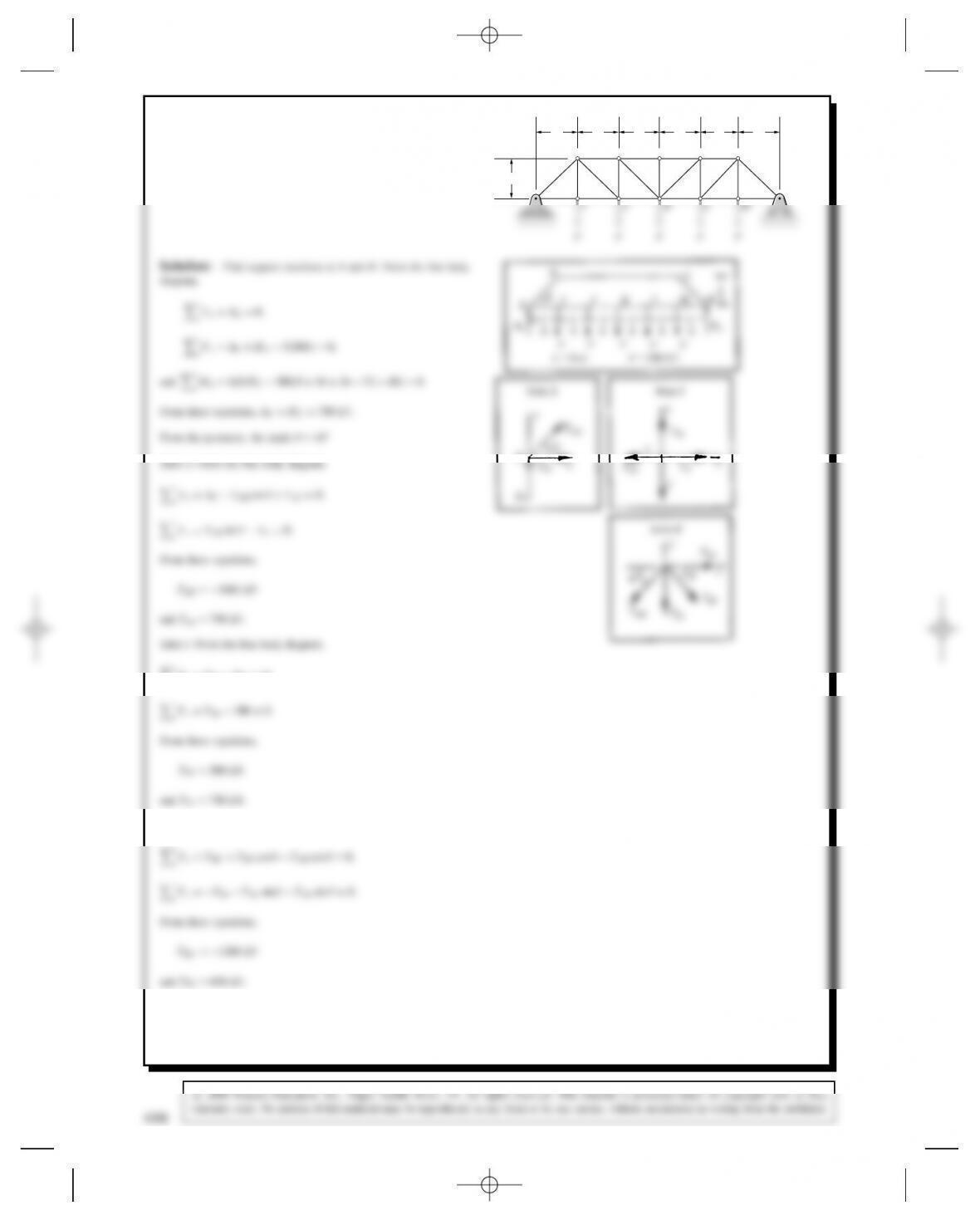
Problem 6.24 The Pratt bridge truss supports five
forces (FD300 kN). The dimension LD8 m. Deter-
mine the axial forces in members BC,BI, and BJ.
A
BCDEG
H
LLLLLLLL
LL
408
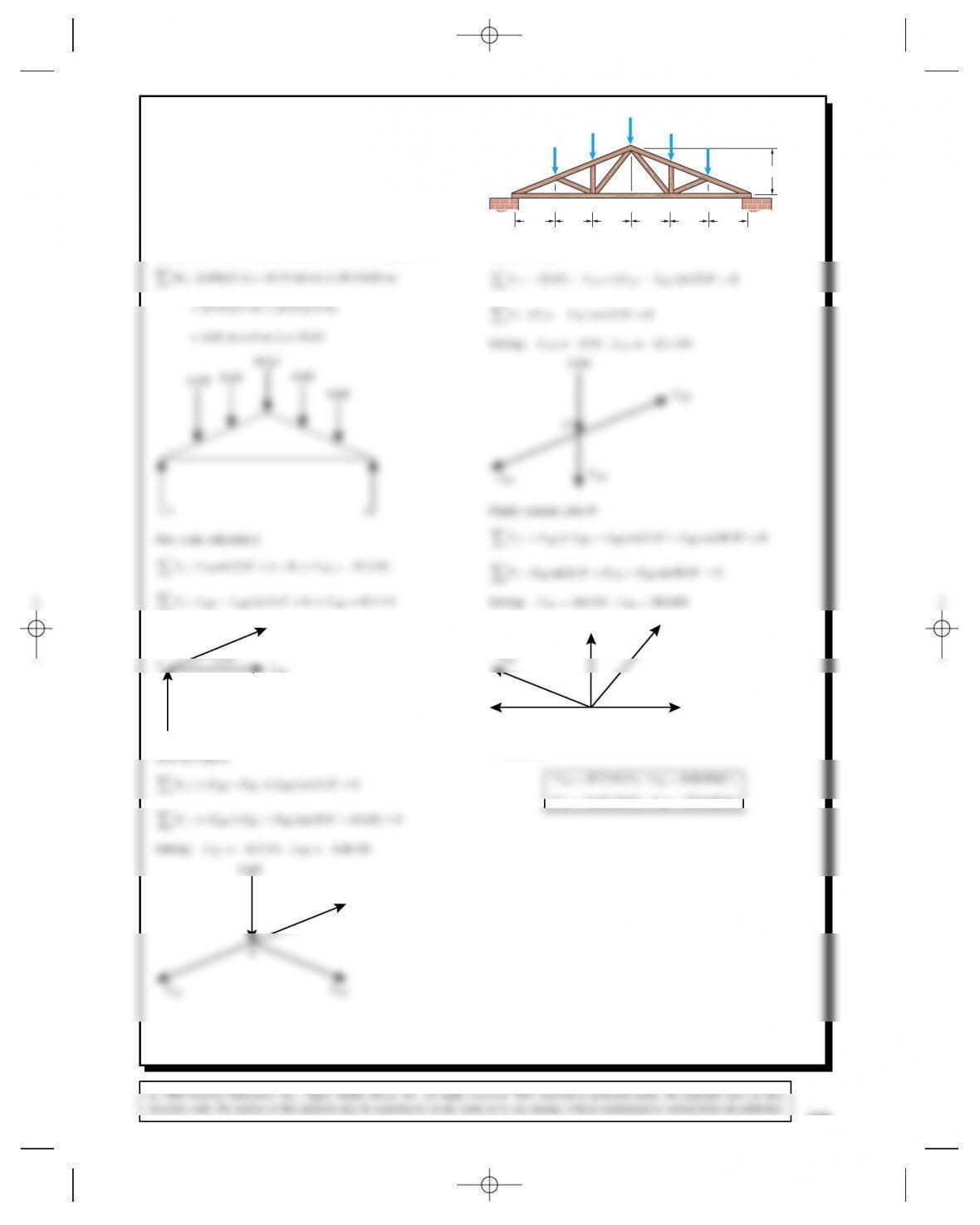
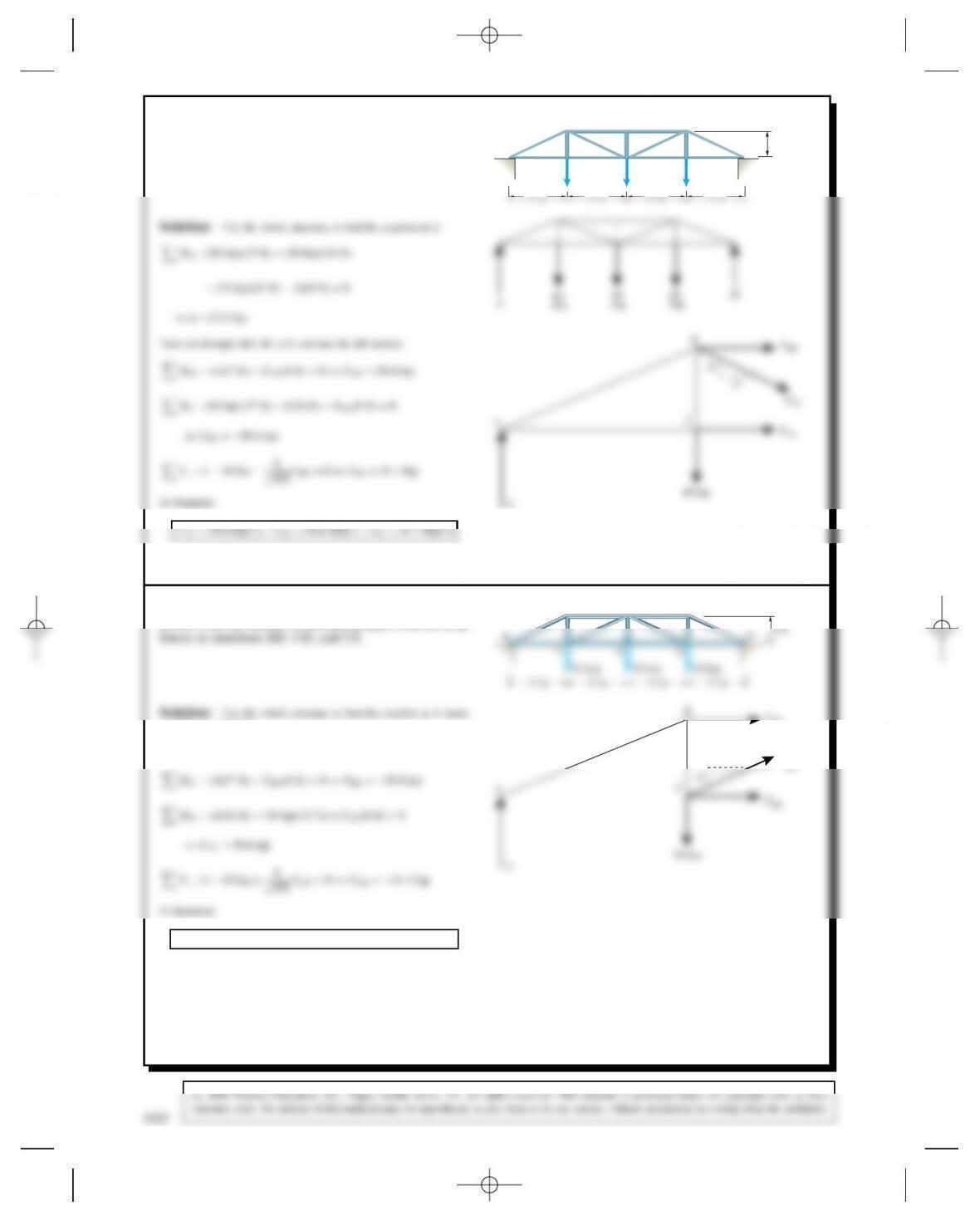
Problem 6.25 For the roof truss shown, determine the
axial forces in members AD, BD, DE, and DG. Model
the supports at Aand Ias roller supports.
A
B
CF
H
I
E
3 m 3 m 3 m 3 m 3 m 3 m
DG
6 kN 6 kN
8 kN 8 kN
10 kN
3.6 m
Solution: Use the whole structure to find the reaction at A.
FAB
Next go to joint C
FCD
FDE
Problem 6.26 The Howe truss helps support a roof.
Model the supports at Aand Gas roller supports. Deter-
mine the axial forces in members AB,BC, and CD.
800 lb
A
C
G
E
D
600 lb
600 lb
400 lb400 lb
˛Pitch Dtan18
12 D33.7°.
˛HIB Dtan12.6667
4D33.7°.
from which AD33600
24 D1400 lb. Check: The total load is 2800 lb.
From left-right symmetry each support A,Gsupports half the total
4 ft 4 ft 4 ft 4 ft 4 ft 4 ft
AB
CI CJ
BC
HI IJ
BC
BH
400 lb
α
Joint I Joint C
Joint H :
CBI cos ˛Pitch D0,
410
6.26 (Continued)
FyD400 AB sin ˛Pitch CBC sin ˛Pitch
BI sin ˛Pitch D0,
from which BC BI DAB C400
sin ˛Pitch
.
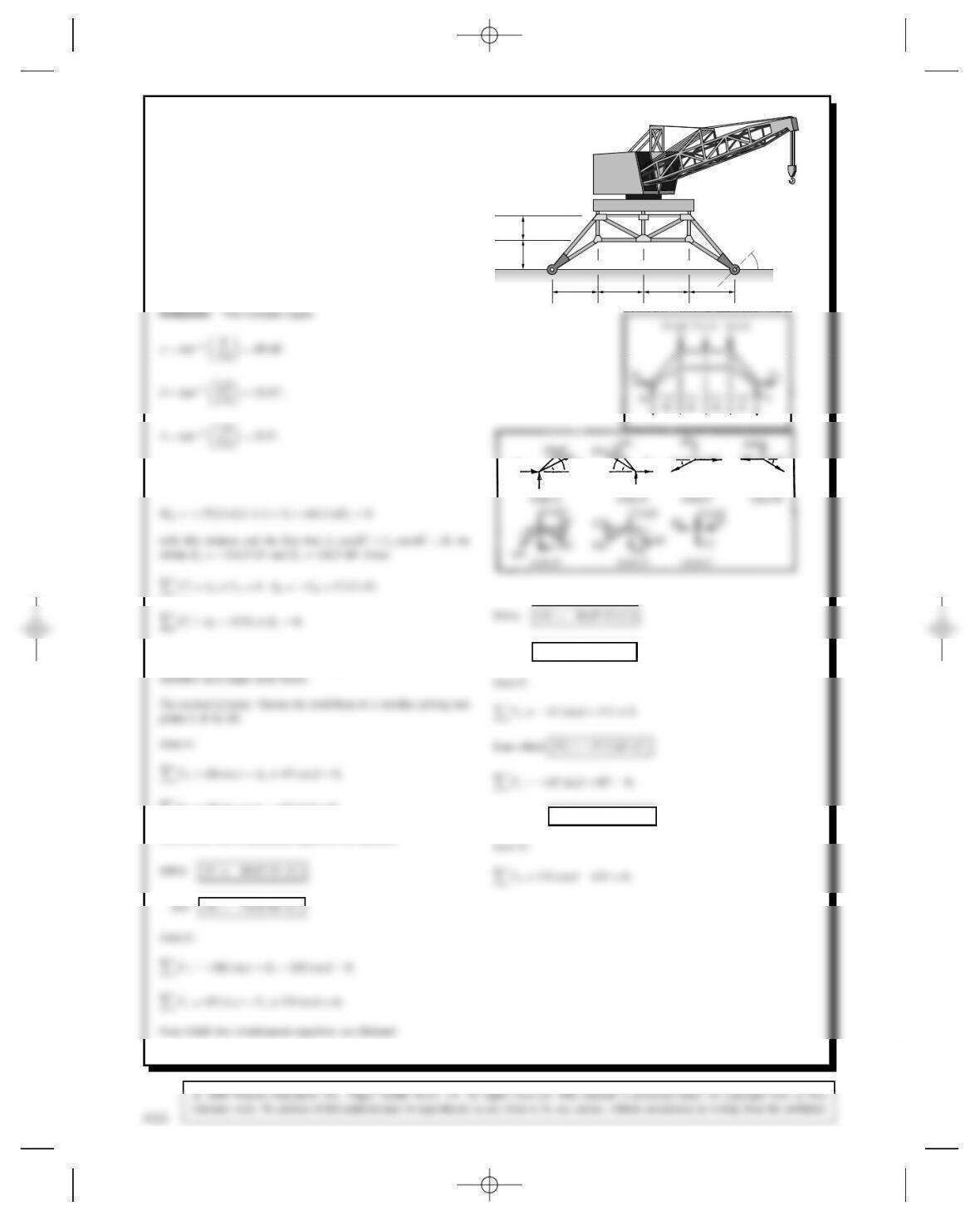
Problem 6.27 The plane truss forms part of the
supports of a crane on an offshore oil platform. The
crane exerts vertical 75-kN forces on the truss at B,C,
and D. You can model the support at Aas a pin support
and model the support at Eas a roller support that can
exert a force normal to the dashed line but cannot exert
a force parallel to it. The angle ˛D45°. Determine the
axial forces in the members of the truss.
3.4 m3.4 m 3.4 m3.4 m
1.8 m
2.2 m AE
FGH
CDB
α
The complete structure as a free body: The sum of the moments about
Ais
from which AyD112.5 kN. Thus the reactions at Aand Eare symmet-
rical about the truss center, which suggests that symmetrical truss
from which two simultaneous equations are obtained.
AX
AYEY
EX
AF
γ
γ
ββ
β
β
AF FG GH
EH
Joint A Joint E Joint F
Joint H
and DE D115.8kN⊲C⊳
from which BF D24.26 kN ⊲C⊳
412
6.27 (Continued)
from which GH D37.5kN⊲C⊳
from which DG D80.1kN⊲T⊳
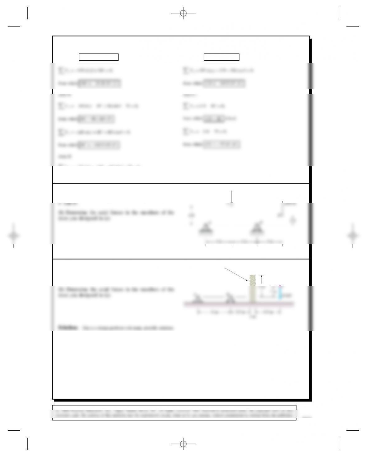
Problem 6.28 (a) Design a truss attached to the
supports Aand Bthat supports the loads applied at points
1000 lb
Problem 6.29 (a) Design a truss attached to the
supports A and B that goes over the obstacle and
supports the load applied at C.
(b) Determine the axial forces in the members of the
truss you designed in (a). AB
C
4 m
Obstacle
2 m 10 kN
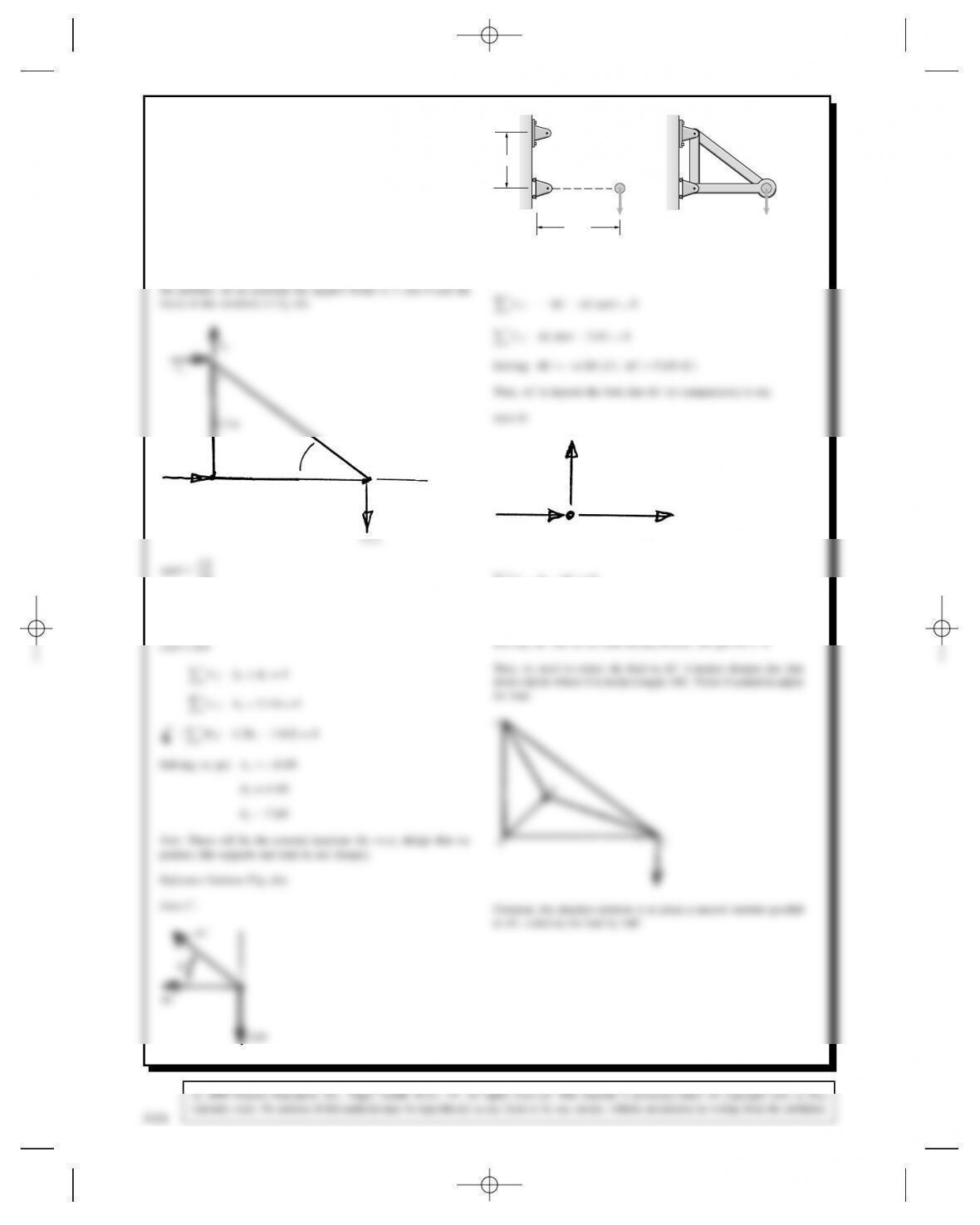
Problem 6.30 Suppose that you want to design a truss
supported at Aand B(Fig. a) to support a 3-kN down-
ward load at C. The simplest design (Fig. b) subjects
member AC to 5-kN tensile force. Redesign the truss so
that the largest force is less than 3 kN.
A
B
C
A
B
C
3 kN
1.2 m
1.6 m
(a) (b)
3 kN
Solution: There are many possible designs. To better understand
Bx
C
x
B1.6 m
3 kN
1.2 m
θ
1.6
D36.87°
sin D0.6
D36.87°
BX
AB
BC
Fy:AB D0
414
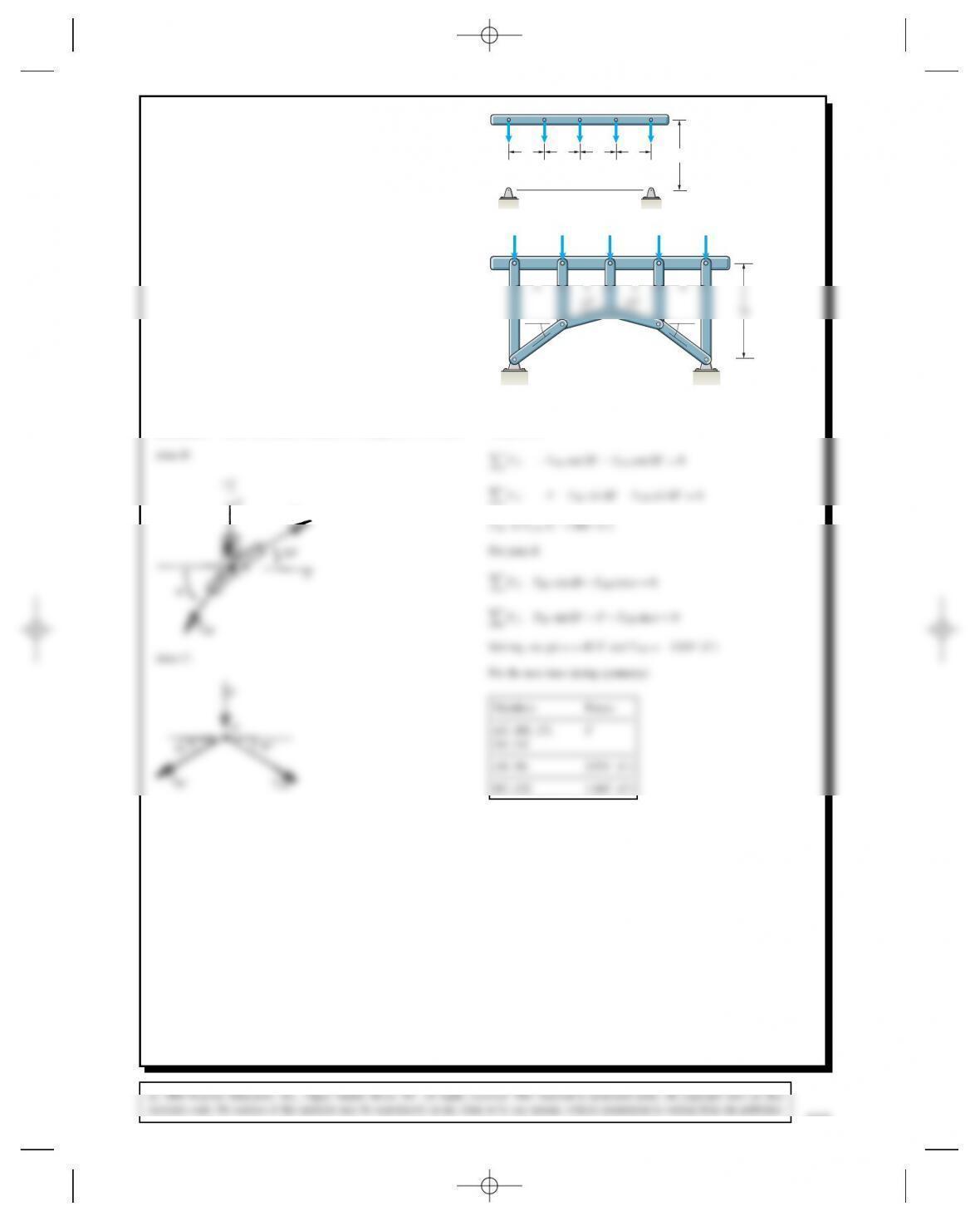
Problem 6.31 The bridge structure shown in Example
6.2 can be given a higher arch by increasing the 15°
angles to 20°. If this is done, what are the axial forces
in members AB,BC,CD, and DE?2b
FFFFF
bbbb
(1)
FFF
(2)
B
C
D
EA
GJIKH
FF
aa
Solution: Follow the solution method in Example 6.3. Fis known
For joint C,
Problem 6.32 In Active Example 6.3, use the method
of sections to determine the axial forces in members BC,
BI and HI.
ABCDE F
M
1 m
Problem 6.33 In Example 6.4, obtain a section of the
truss by passing planes through members BE,CE,CG,
and DG. Using the fact that the axial forces in members
DG and BE have already been determined, use your
L
D
GJ
416
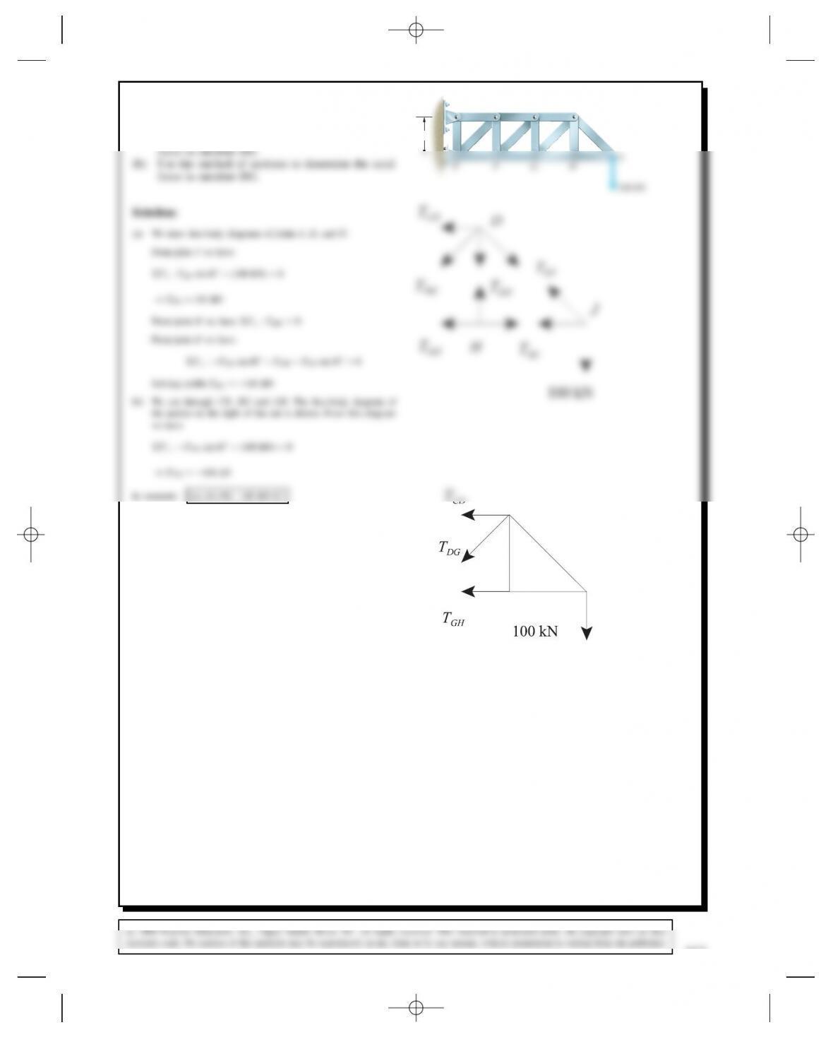
Problem 6.34 The truss supports a 100-kN load at J.
The horizontal members are each 1 m in length.
(a) Use the method of joints to determine the axial
ABCD
100 kN
1 m
Problem 6.35 For the truss in Problem 6.34, use the
method of sections to determine the axial forces in
members BC,CF, and FG.
Solving BC D300 kN ⊲T⊳
CF D141.4kN⊲C⊳
FG D200 kN ⊲C⊳
Problem 6.36 Use the method of sections to determine
AX
AY
GY
B
F
2F
D
CE
θ
1 m
Θ
= 45°
Fx:AxD0
Fy:AyCGy3FD0
AX = 0
AY
AB
CE
1 m
1 m
y
B
C
F
x
AY = 1. 33 F
AX = 0
CE D1.33F⊲T⊳
418
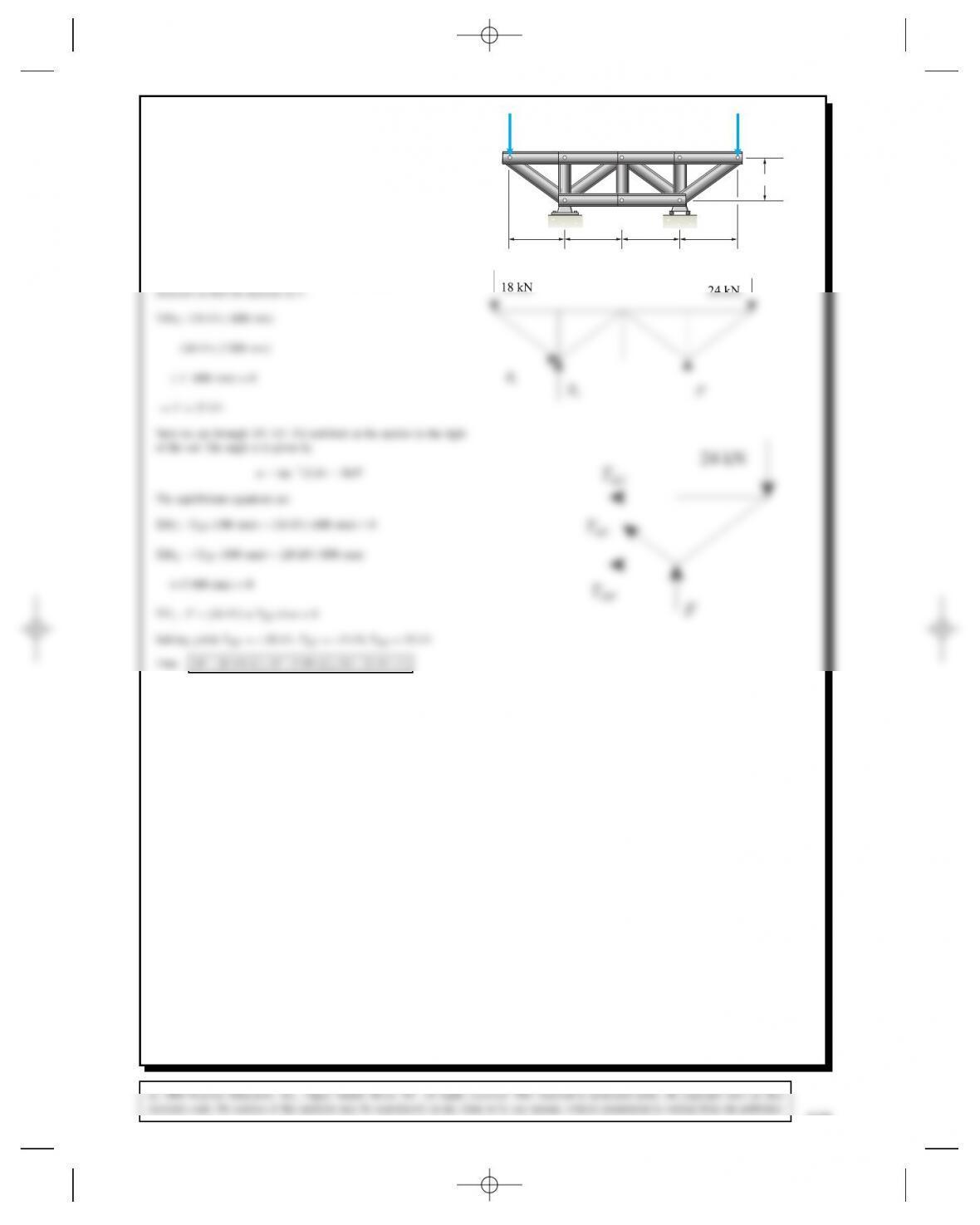
Problem 6.37 Use the method of sections to determine
the axial forces in members DF,EF, and EG.
A
B
C
D
E
F
GH
300 mm
400 mm 400 mm 400 mm 400 mm
18 kN 24 kN
Solution: We will first use the free-body diagram of the entire
Problem 6.38 The Pratt bridge truss is loaded as
shown. Use the method of sections to determine the axial
forces in members BD, BE, and CE.
A
BDF
H
GEC
8 ft
10 kip 30 kip 20 kip
MB:A⊲17 ft⊳CFCE⊲8ft⊳D0)FCE D58.4 kip
ME:⊲10 kip⊳⊲17 ft⊳A⊲34 ft⊳FBD⊲8ft⊳D0
)FBD D95.6 kip
Fy:A10 kip 8
p353 FBE D0)FBE D41.1 kip
In Summary
FCE D58.4 kip⊲T⊳, FBD D95.6 kip⊲C⊳, FBE D41.1 kip⊲T⊳
A
C
8
17
A
10 kip
FCE
FBE
Problem 6.39 The Howe bridge truss is loaded as
shown. Use the method of sections to determine the axial
BDF
8 ft
as 6.38) AD27.5 kip
Now cut through BD,CD, and CE and use the left section.
FCD
17
420
Problem 6.40 For the Howe bridge truss in Problem
6.39, use the method of sections to determine the axial
forces in members DF, DG, and EG.
Solution: Same truss as 6.39.
D0)FDF D69.1 kip
FEG D95.6 kip⊲T⊳, FDF D69.1 kip⊲C⊳, FDG D29.4 kip⊲C⊳
FDF
D
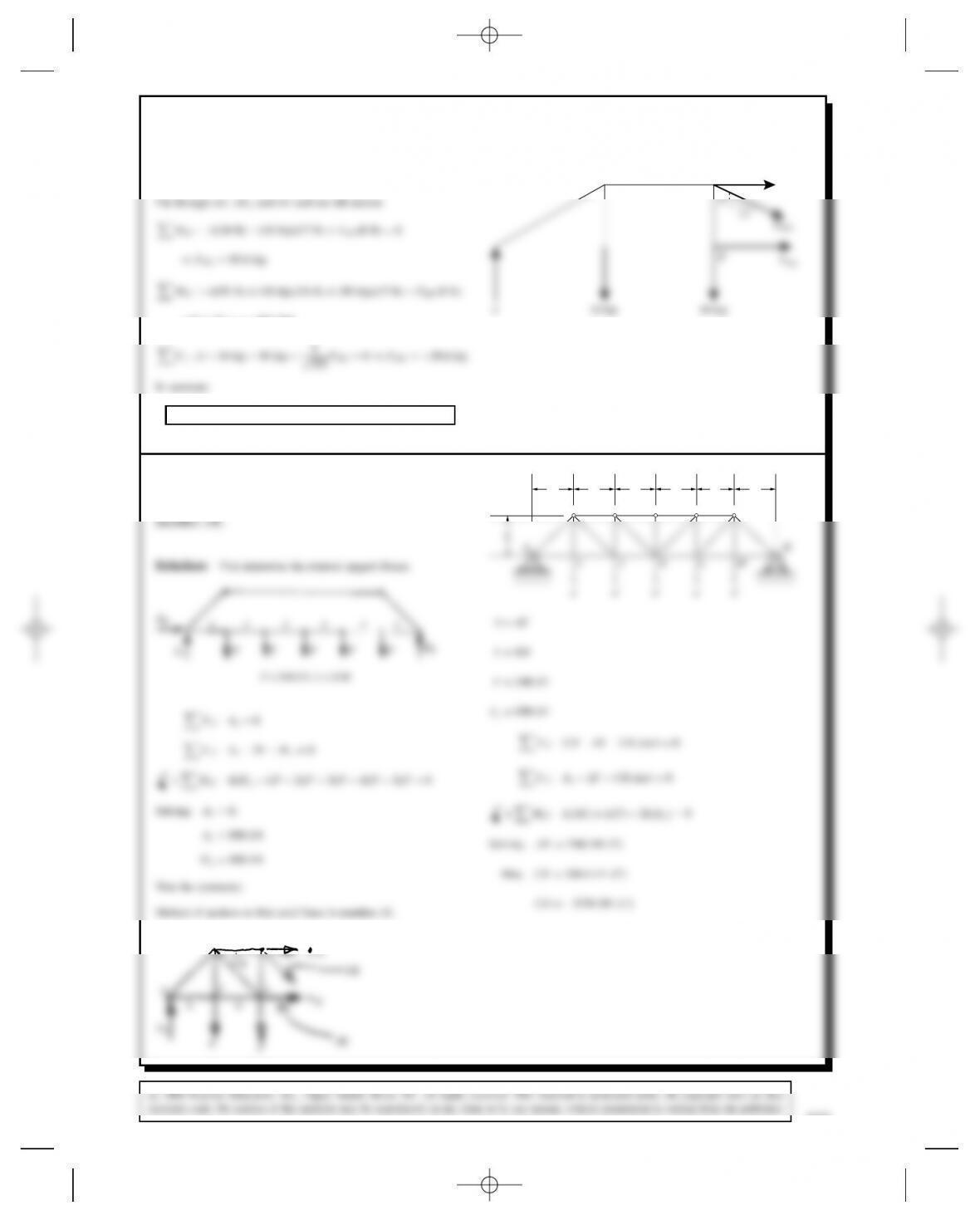
Problem 6.41 The Pratt bridge truss supports five
forces FD340 kN. The dimension LD8 m. Use the
method of sections to determine the axial force in
BCDEG
IJKLM
LLLLLLLL
Solution: First determine the external support forces.
B
A
AY
LL
J
I
K
CK
D
CD
C
θ
Problem 6.42 For the Pratt bridge truss in Prob-
lem 6.41, use the method of sections to determine the
axial force in member EK.
Solution: From the solution to Problem 6.41, the support forces
DE
θ
Fx:DE EK cos KL D0
Fy:Hy2FEK sin D0
ME:⊲L⊳⊲KL⊳ ⊲L⊳⊲F⊳ C⊲2L⊳HyD0
IJKLM
LL LLLL
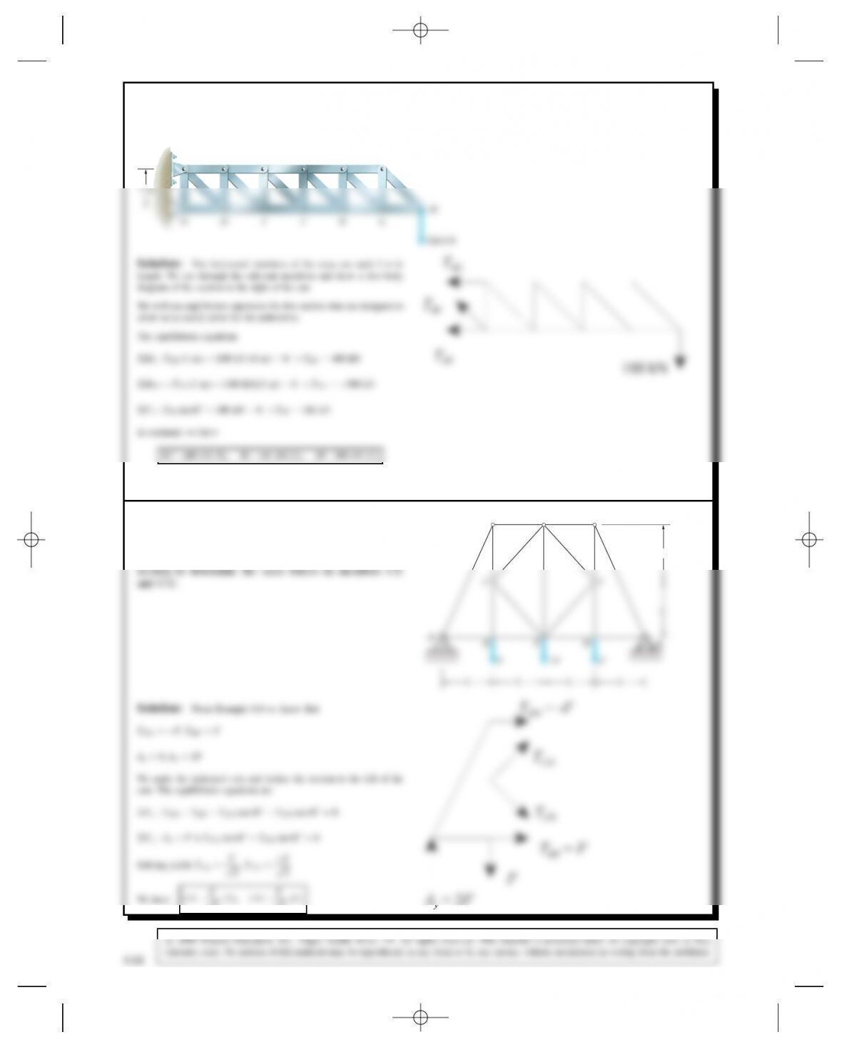
Problem 6.43 The walkway exerts vertical 50-kN
loads on the Warren truss at B,D,F, and H. Use
the method of sections to determine the axial force in
member CE.
6 m6 m6 m6 m
ACEGI
BDFH
2 m
Solution: First, find the external support forces. By symmetry,
AyDIyD100 kN (we solved this problem earlier by the method of
joints).
Solving: CE D300 kN ⊲T⊳
Also, BD D225 kN ⊲C⊳
422
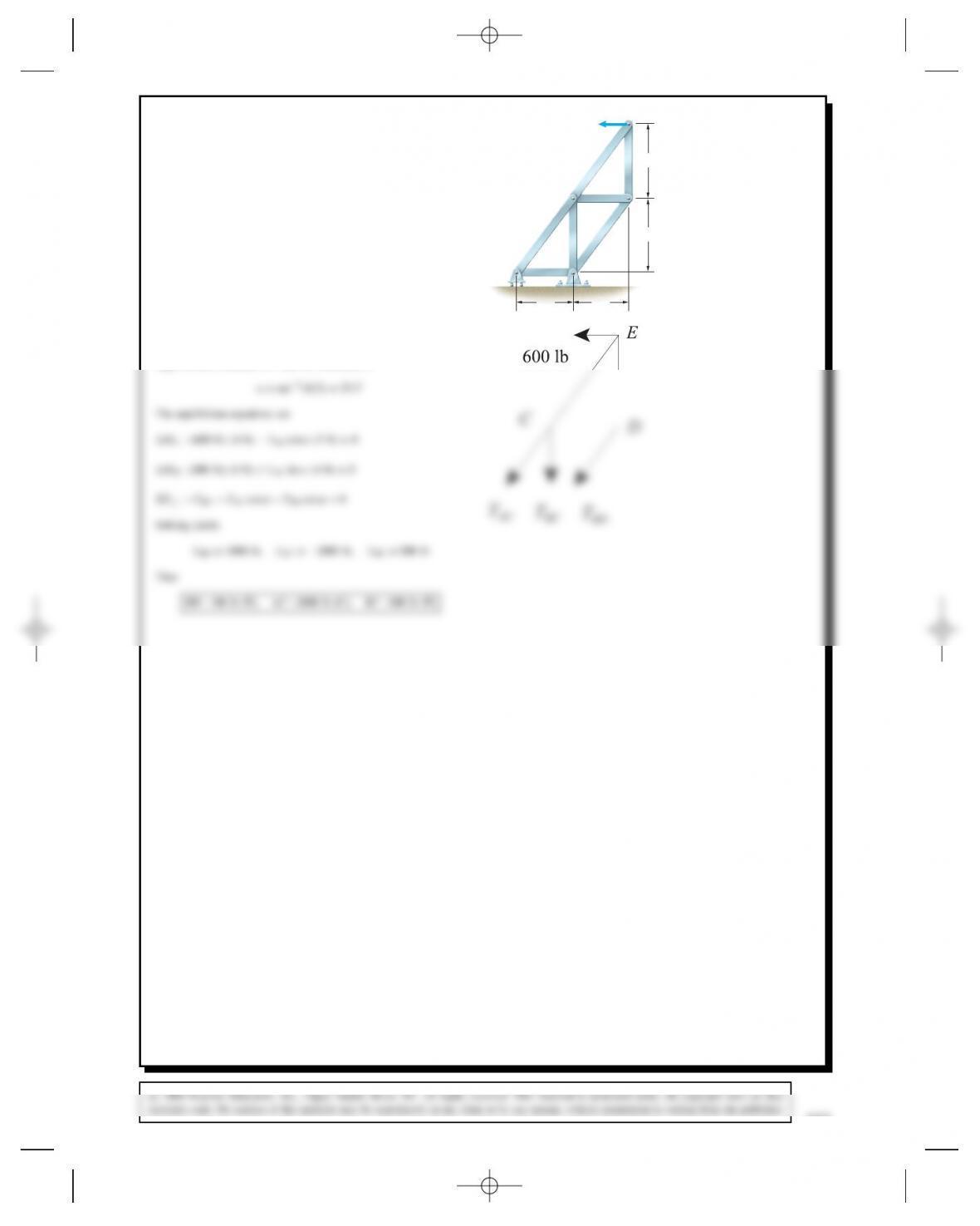
Problem 6.44 Use the method of sections to determine
the axial forces in members AC,BC, and BD.600 lb
D
E
3 ft
4 f
t
4 f
t
3 ft
A
C
B
Solution: Obtain a section by passing a plane through members
AC,BC, and BD, isolating the part of the truss above the planes. The
angle between member AC and the horizontal is
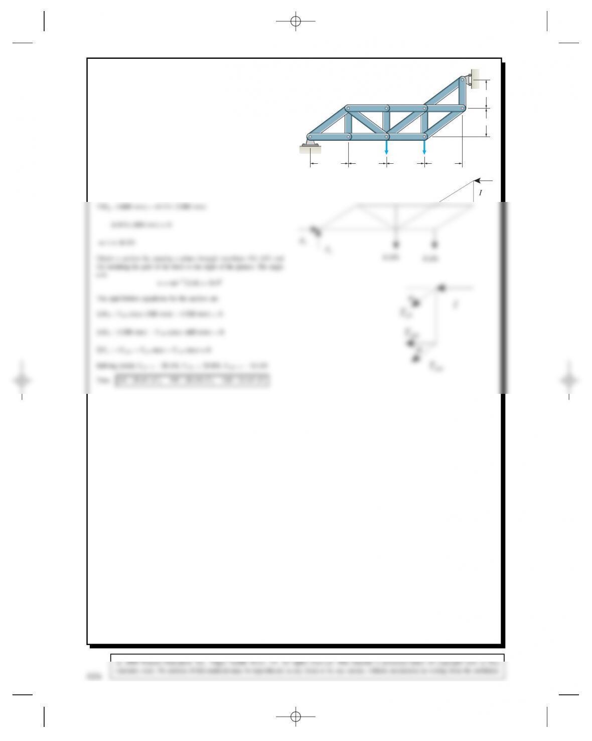
Problem 6.45 Use the method of sections to determine
the axial forces in member FH,GH, and GI.
I
C
A
BD F
H
EG
400 mm 400 mm
6 kN 4 kN
400 mm400 mm
300 mm
300 mm
Solution: The free-body diagram of the entire truss is used to find
the force I.
424
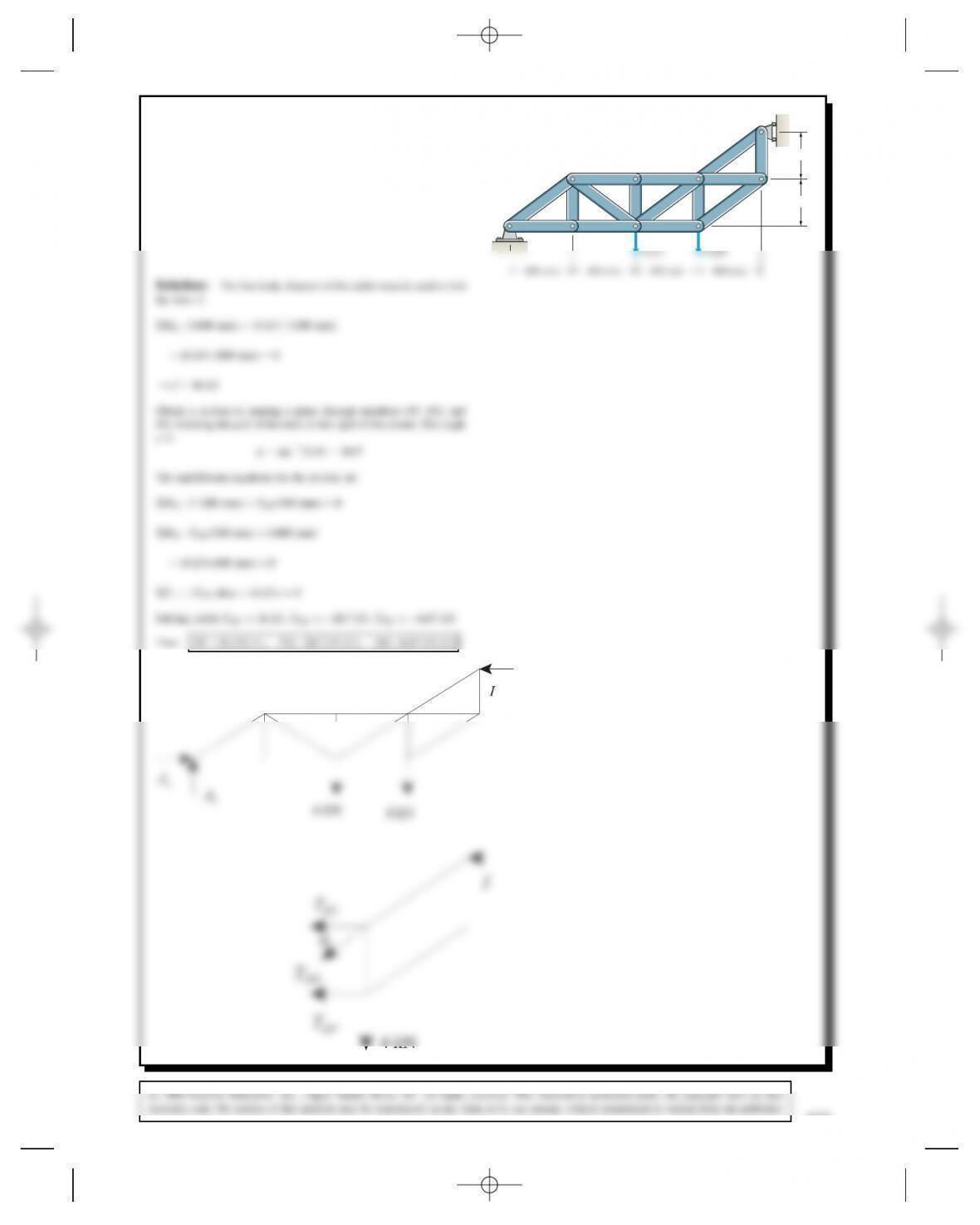
Problem 6.46 Use the method of sections to determine
the axial forces in member DF,DG, and EG.
I
C
A
BD F
H
EG
6 kN 4 kN
300 mm
300 mm