Unlock document.
This document is partially blurred.
Unlock all pages and 1 million more documents.
Get Access
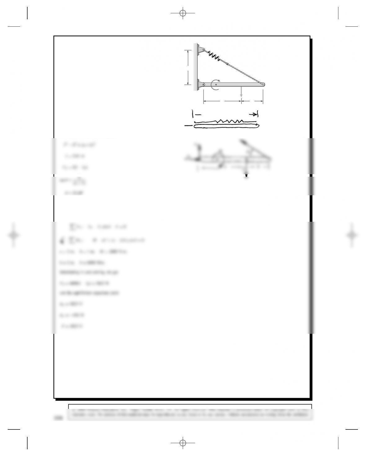
Problem 5.61 The dimensions aD2 m and bD1m.
The couple MD2400 N-m. The spring constant is kD
6000 N/m, and the spring would be unstretched if hD0.
The system is in equilibrium when hD2 m and the
beam is horizontal. Determine the force Fand the reac-
tions at A.
a
A
k
M
b
F
h
Solution: We need to know the unstretched length of the spring, l0
l0DaCbD3m
We also need the stretched length
Unstretched
(a + b)
308
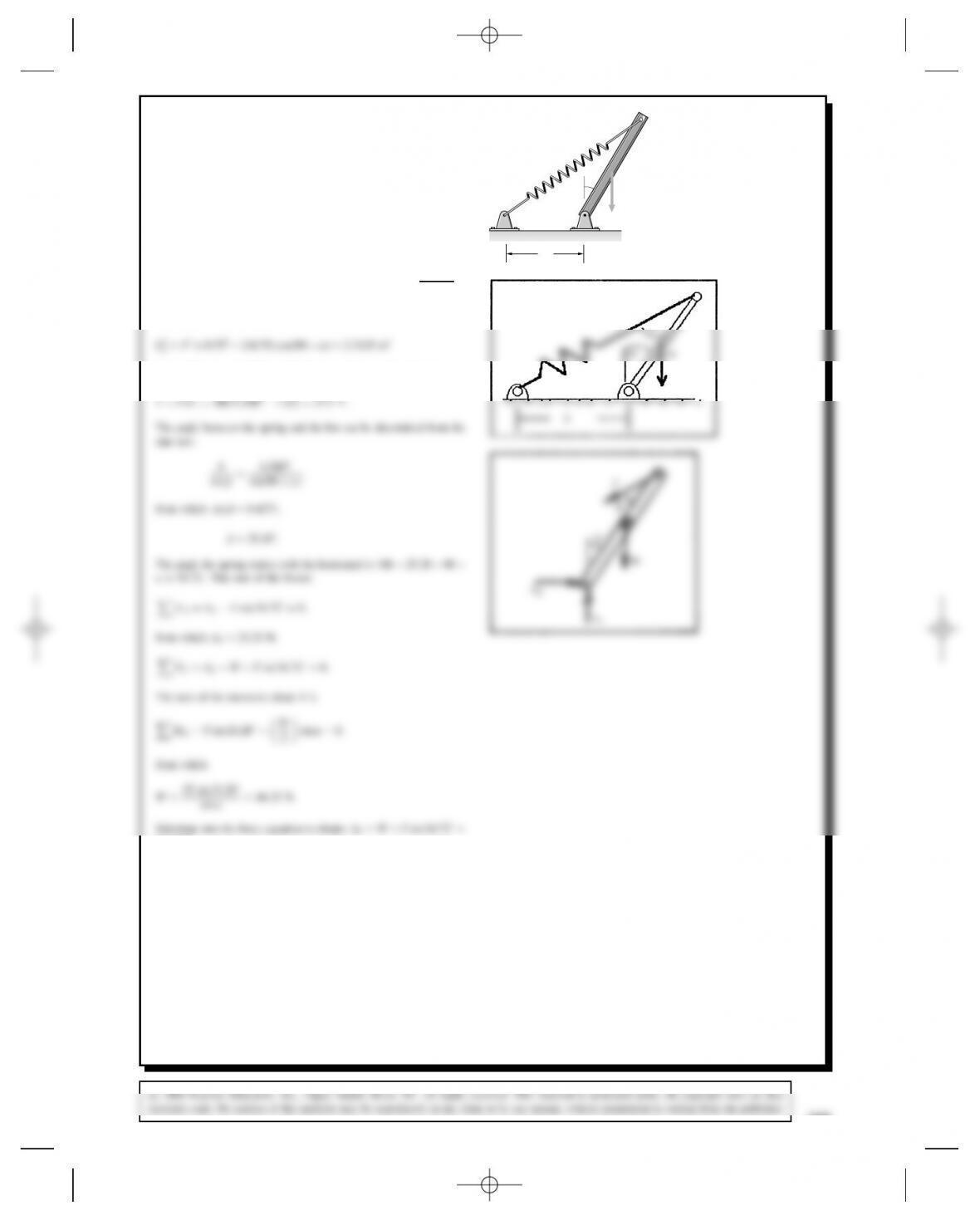
Problem 5.62 The bar is 1 m long, and its weight W
acts at its midpoint. The distance bD0.75 m, and the
angle ˛D30°. The spring constant is kD100 N/m, and
the spring is unstretched when the bar is vertical. Deter-
mine Wand the reactions at A.
b
W
A
k
α
Solution: The unstretched length of the spring is LDpb2C12D
1.25 m. The obtuse angle is 90 C˛, so the stretched length can be
determined from the cosine law:
from which L2D1.5207 m. The force exerted by the spring is
A
β
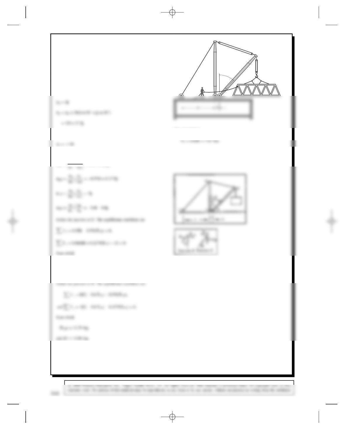
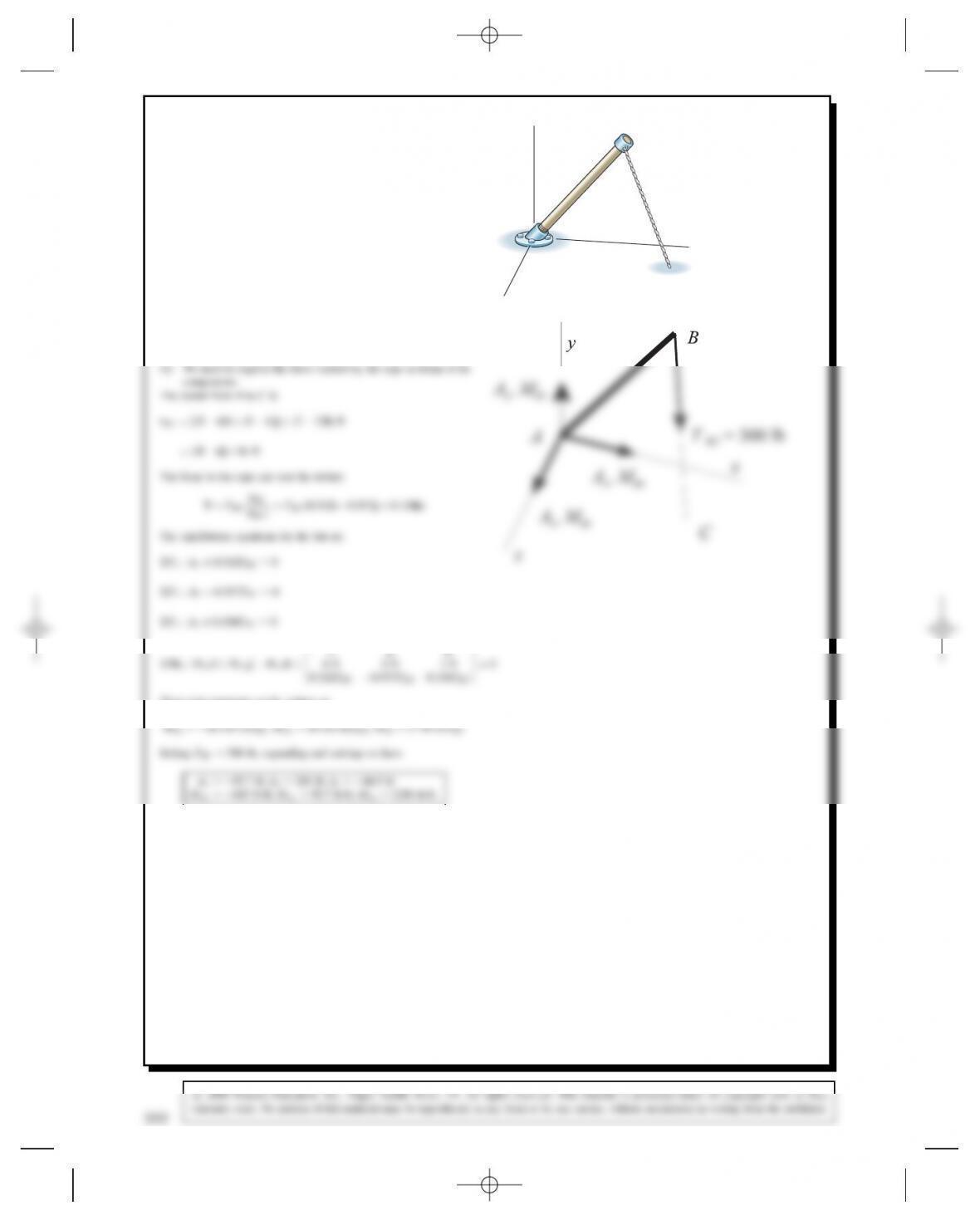
Problem 5.63 The boom derrick supports a suspended
15-kip load. The booms BC and DE are each 20 ft long.
The distances are aD15 ft and bD2 ft, and the angle
D30°. Determine the tension in cable AB and the reac-
tions at the pin supports Cand D.
CDA
E
B
θ
Solution: Choose a coordinate system with origin at point C, with
the yaxis parallel to CB. The position vectors of the labeled points
are:
rBD20j,
The unit vectors are:
eDE DrErD
The components:
DyD0.866jDjD13.287 kip,
and CyD1jCjD11.94 kip
310
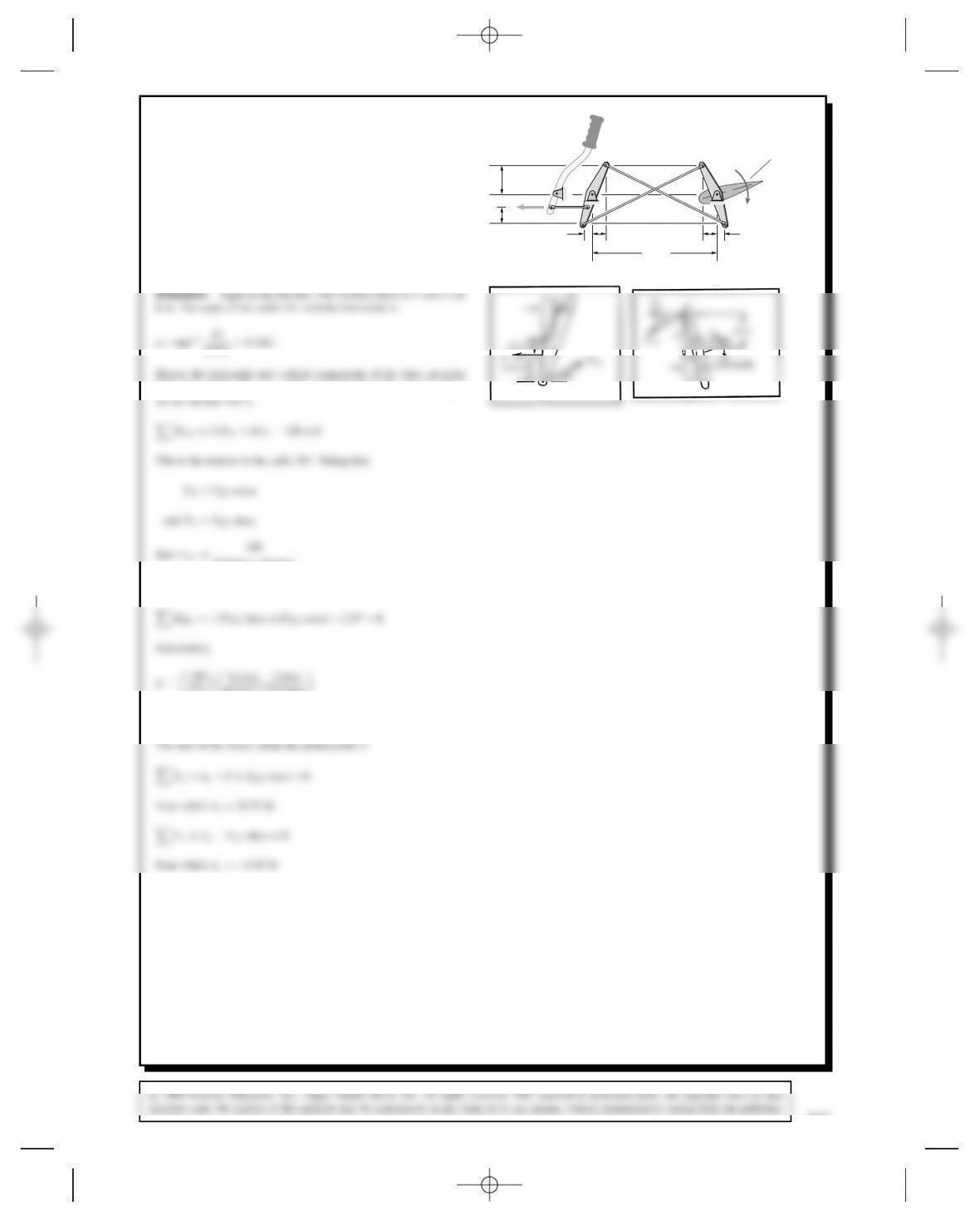
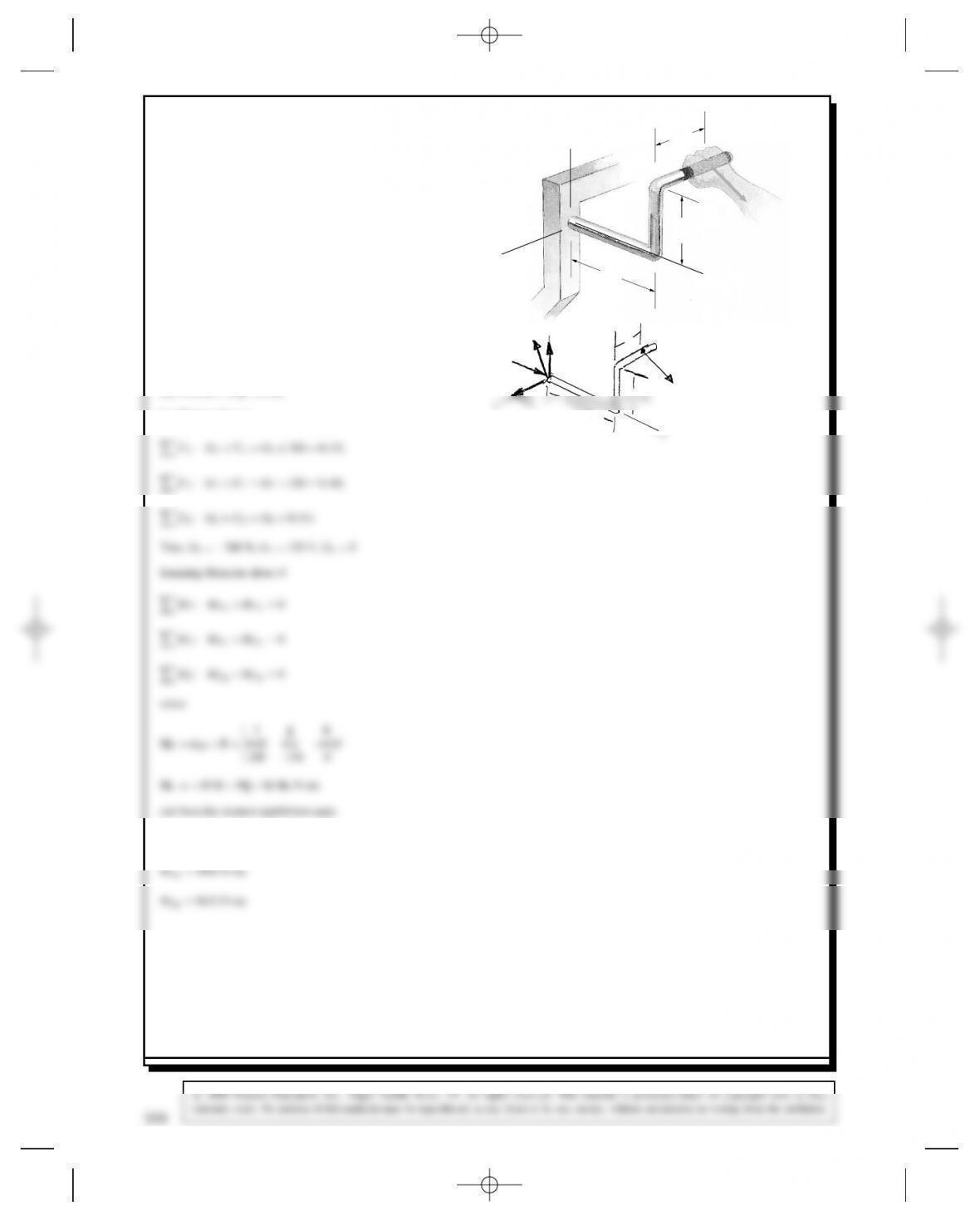
Problem 5.64 The arrangement shown controls the
elevators of an airplane. (The elevators are the horizontal
control surfaces in the airplane’s tail.) The elevators are
attached to member EDG. Aerodynamic pressures on the
elevators exert a clockwise couple of 120 in-lb. Cable
BG is slack, and its tension can be neglected. Determine
the force Fand the reactions at pin support A.
2.5 in
120 in
(Not to scale)
2.5 in2 in
E
B
FC
2.5 in
6 in
3.5 in
D
A
1.5 in
120 in-lb
Elevator
G
119.5D5.734°.
Eby FXand FY. The sum of the moments about the pinned support
2.5 sin ˛C6 cos ˛.
The sum of the moments about the pinned support BC is
2.5 6 cos ˛2 sin ˛
6 cos ˛C2.5 sin ˛
D⊲48⊳⊲0.9277⊳D44.53 lb.
The sum of the forces about the pinned joint A:
FxDAxFCTEC cos ˛D0
from which AxD25.33 lb,
FyDAyCTEC sin ˛D0
from which AyD1.93 lb
FTEC
A
3.5 in
C
120 in-lb
2.5
in
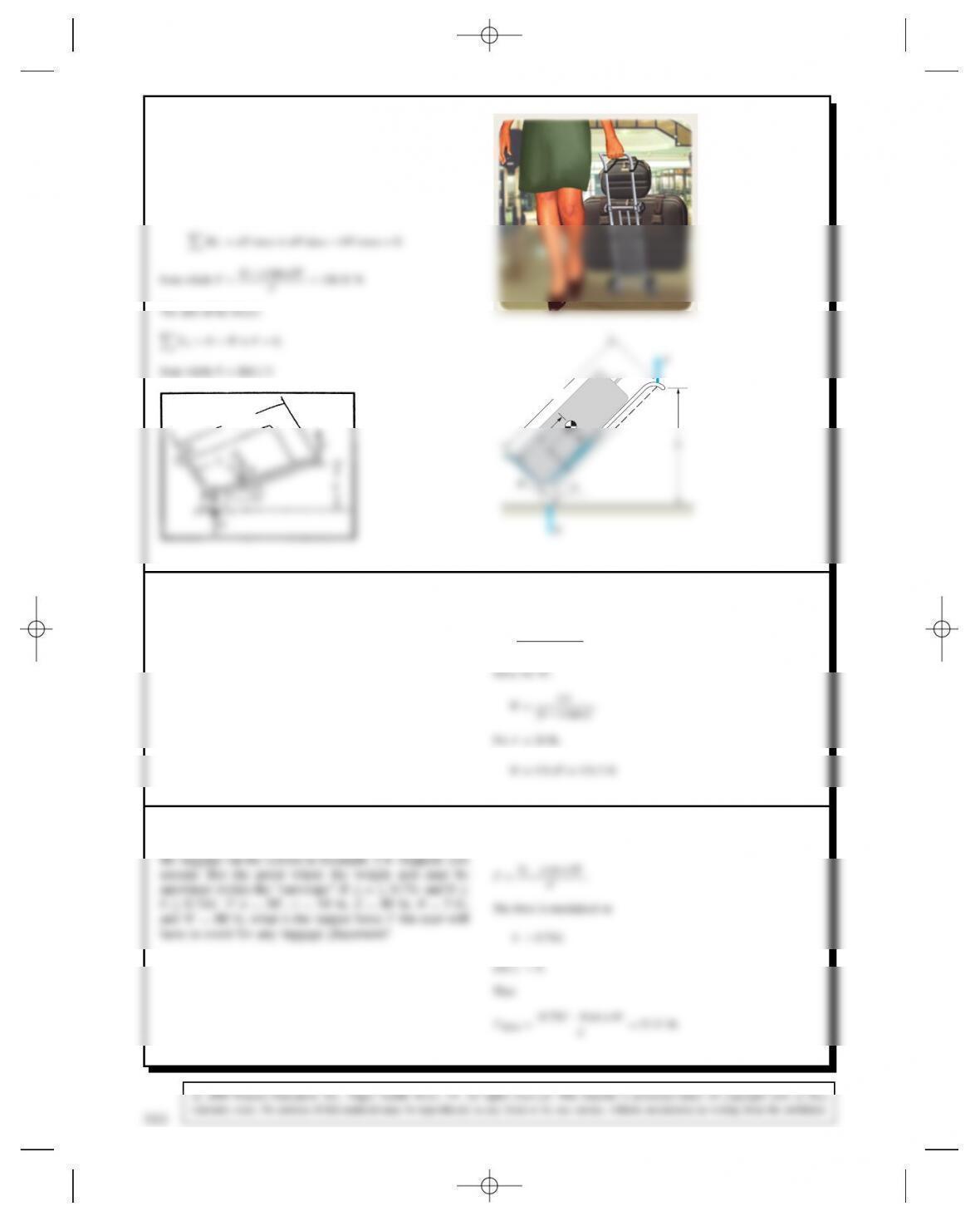
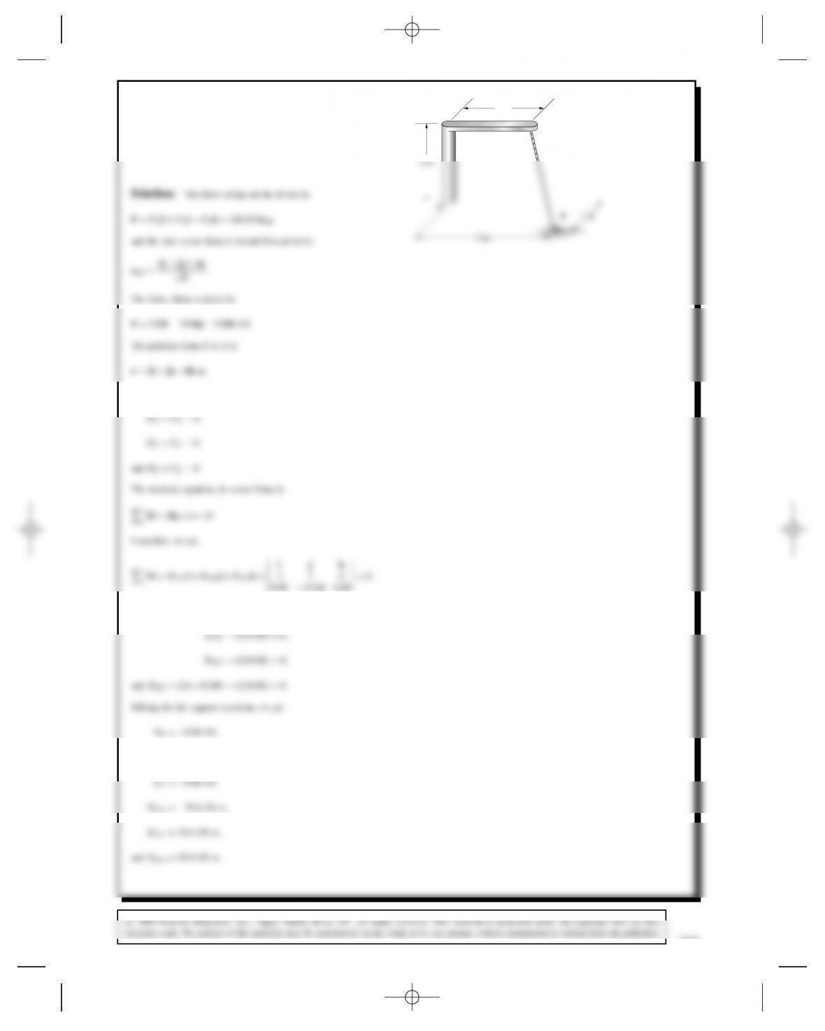
Problem 5.65 In Example 5.4 suppose that ˛D40°,
dD1m,aD200 mm, bD500 mm, RD75 mm, and
the mass of the luggage is 40 kg. Determine Fand N.
N
Solution: (See Example 5.4.)
The sum of the moments about the center of the wheel:
C
N
Problem 5.66 In Example 5.4 suppose that ˛D35°,
dD46 in, aD10 in, bD14 in, RD3 in, and you don’t
want the user to have to exert a force Flarger than 20 lb.
What is the largest luggage weight that can be placed on
the carrier?
Solution: (See Example 5.4.) From the solution to Problem 5.65,
the force is
FD⊲b atan ˛⊳W
d.
Problem 5.67 One of the difficulties in making design
decisions is that you don’t know how the user will place
Solution: (See Example 5.4.) From the solution to Problem 5.65,
the force is
312
Problem 5.68 In our design of the luggage carrier
in Example 5.4, we assumed a user that would hold
the carrier’s handle at hD36 in above the floor. We
assumed that RD3 in, aD6 in, and bD12 in, and we
chose the dimension dD4 ft. The resulting ratio of the
d,
from which F
WD⊲b atan ˛⊳
d.
The angle a is given by
˛Dsin1hR
d.
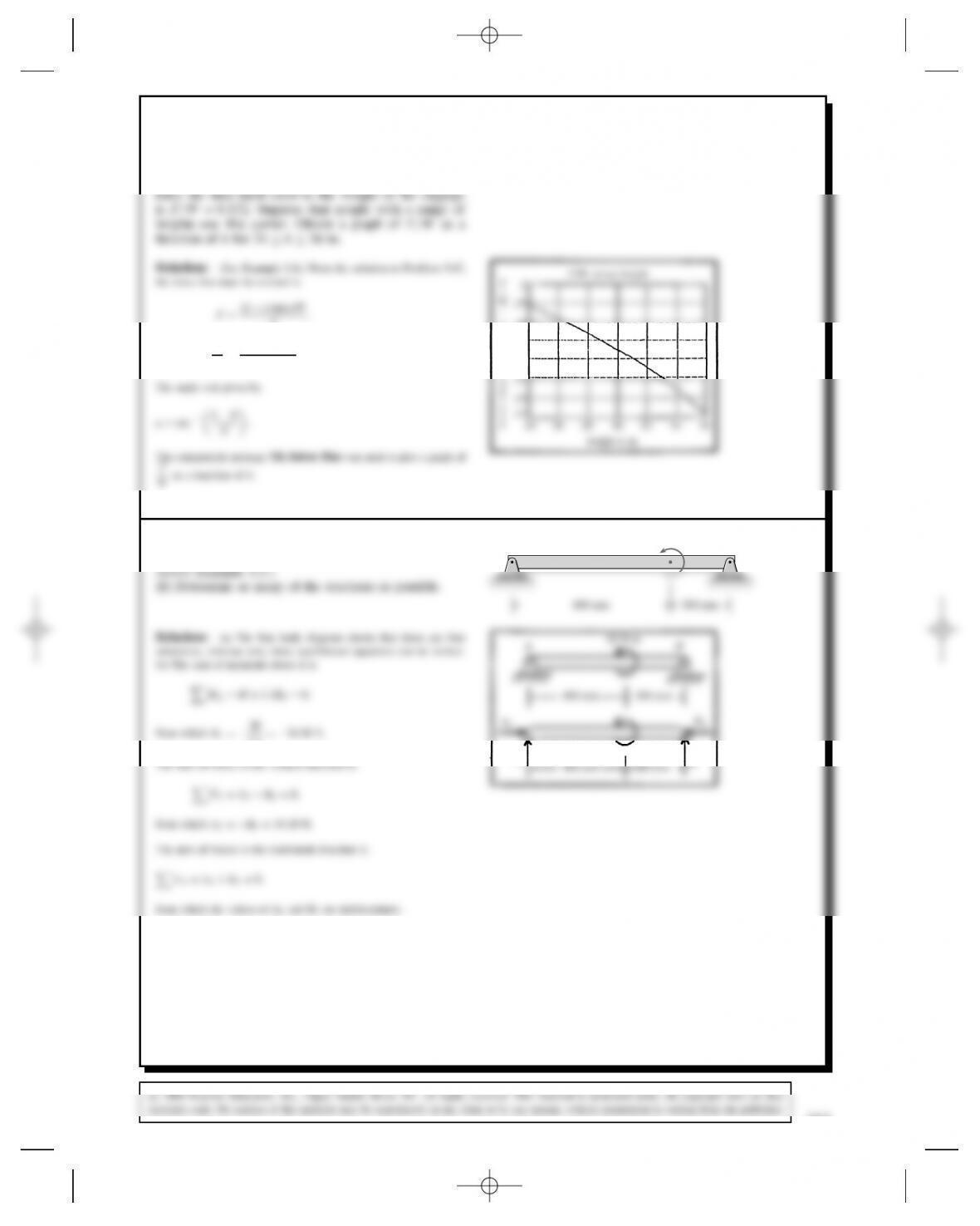
The commercial package TK Solver Plus was used to plot a graph of
F
Was a function of h.
.13
.14
.15
.16
.17
.18
24 26 28 30 32 34 36
height h, in
d
i
m
e
n
s
i
n
l
e
x
e
Problem 5.69 (a) Draw the free-body diagram of the
beam and show that it is statically indeterminate. (See
BA 20 N-m
Problem 5.70 Consider the beam in Problem 5.69.
Choose supports at Aand Bso that it is not statically
indeterminate. Determine the reactions at the supports.
1.1D18.18 N.
The sum of forces in the vertical direction is
FYDAYCBYD0,
from which AYDBYD18.18 N.
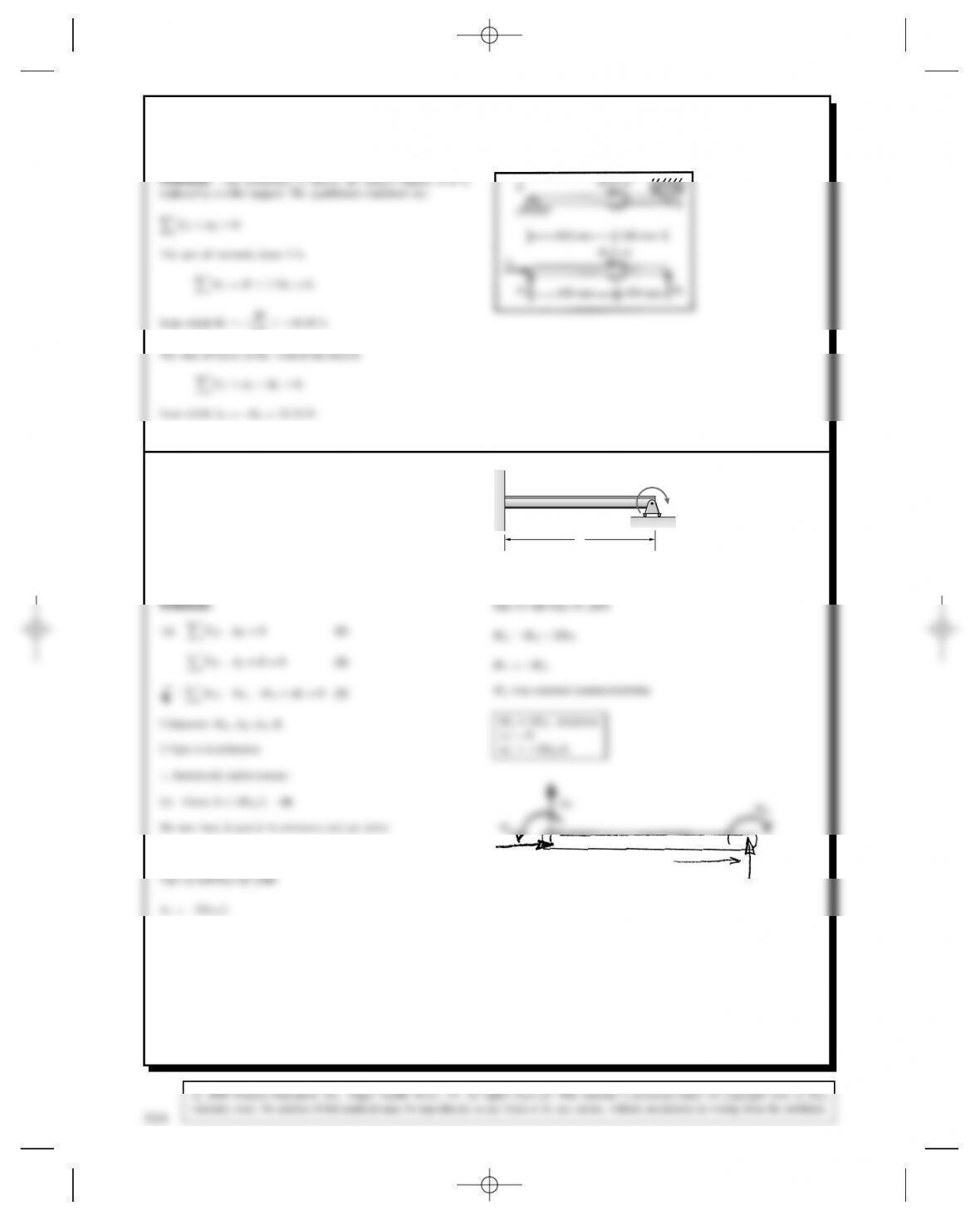
Problem 5.71 (a) Draw the free-body diagram of the
beam and show that it is statically indeterminate. (The
external couple M0is known.)
(b) By an analysis of the beam’s deflection, it is deter-
mined that the vertical reaction Bexerted by the roller
support is related to the couple M0by BD2M0/L. What
are the reactions at A?
A B
L
M0
Eqn (1) yields AXD0
Eqn (2) and Eqn (4) yield
AYD2MO/L
AXL
B
314
c
2008 Pearson Education, Inc., Upper Saddle River, NJ. All rights reserved. This material is protected under all copyright laws as they
currently exist. No portion of this material may be reproduced, in any form or by any means, without permission in writing from the publisher.
Problem 5.72 Consider the beam in Problem 5.71.
Choose supports at Aand Bso that it is not statically
indeterminate. Determine the reactions at the supports.
BDMO/L
AYDMO/L
AY
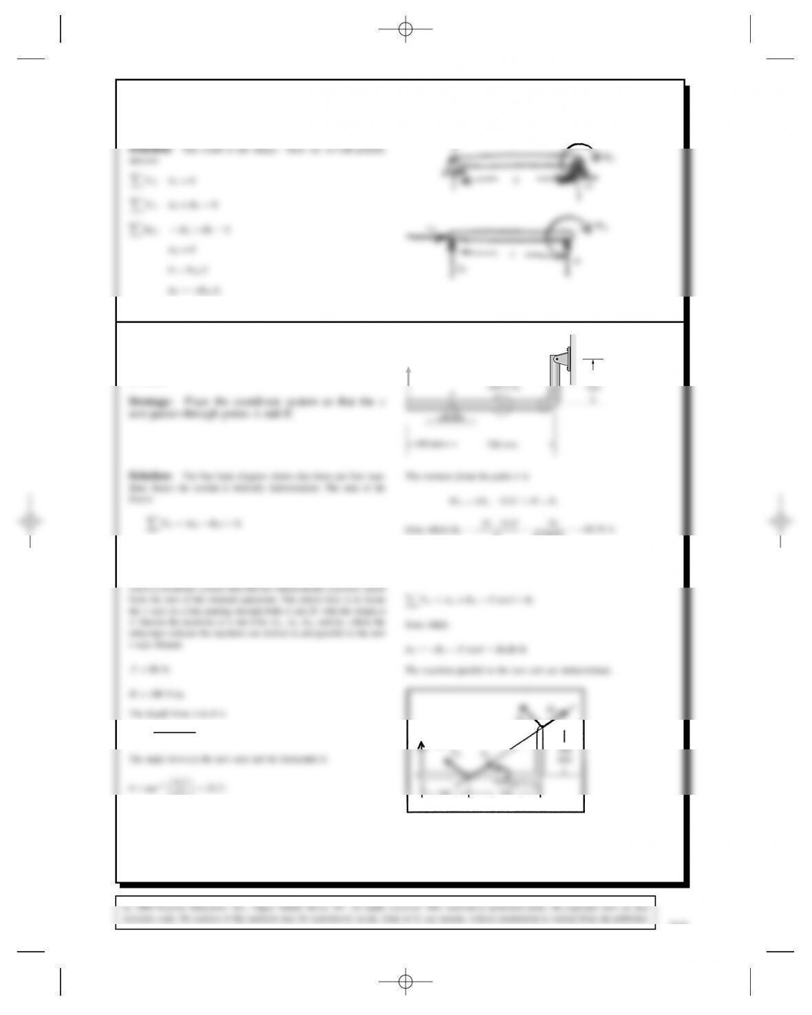
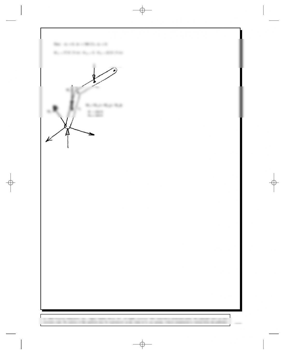
Problem 5.73 Draw the free-body diagram of the
L-shaped pipe assembly and show that it is statically
indeterminate. Determine as many of the reactions as
possible.
B
80 N 300
and FYDAYCBYCFD0.
A strategy for solving some statically indeterminate problems is to
LDp0.32C0.72D0.76157 m.
LD76
0.76157 D99.79 N,
from which
The sum of the forces normal to the new axis is
BN
80 N
Problem 5.74 Consider the pipe assembly in Problem
5.73. Choose supports at Aand Bso that it is not
statically indeterminate. Determine the reactions at the
supports.
Solution: This problem has no unique solution.
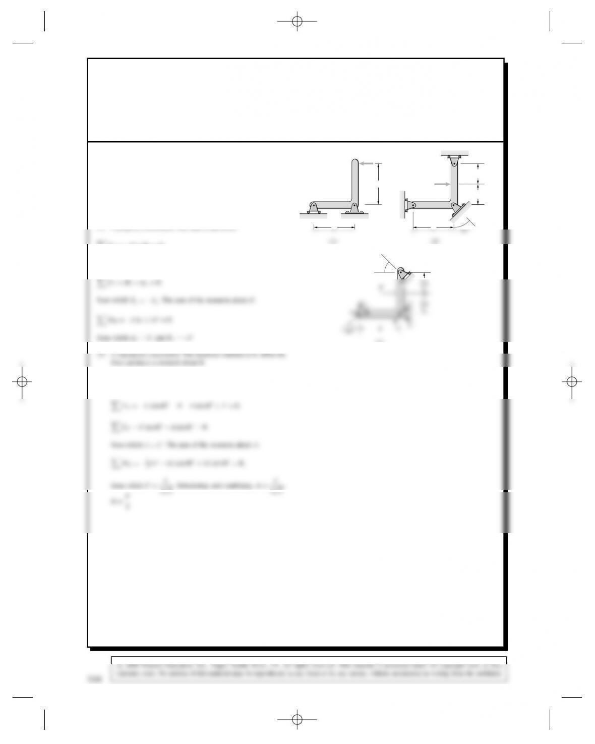
Problem 5.75 State whether each of the L-shaped bars
shown is properly or improperly supported. If a bar
is properly supported, determine the reactions at its
supports. (See Active Example 5.6.)
L
BA
F
– L
B
A
F
1
2
C
– L
1
2
Solution:
(3) is properly constrained. The forces are neither concurrent nor
parallel. The sum of the forces:
316
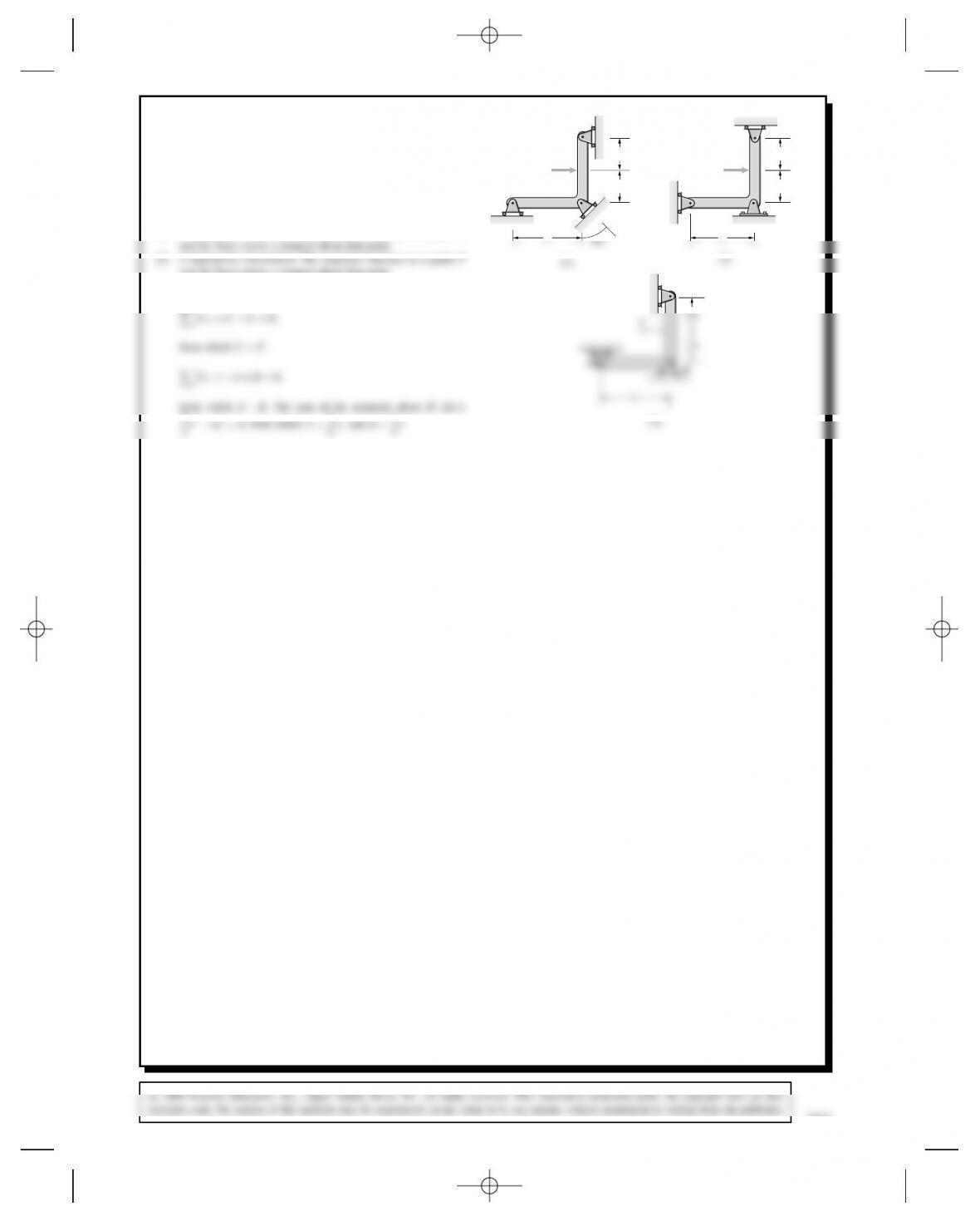
Problem 5.76 State whether each of the L-shaped bars
shown is properly or improperly supported. If a bar
is properly supported, determine the reactions at its
supports. (See Active Example 5.6.)
– L
B
A
F
1
2
C
– L
1
2
(3)
– L
1
C
1
– L
B
A
F
1
2
C
– L
1
2
Solution:
(1) is improperly constrained. The reactions intersect at a point P,
and the force exerts a moment about that point.
(3) is properly constrained. The sum of the forces:
FXDCFD0,
L
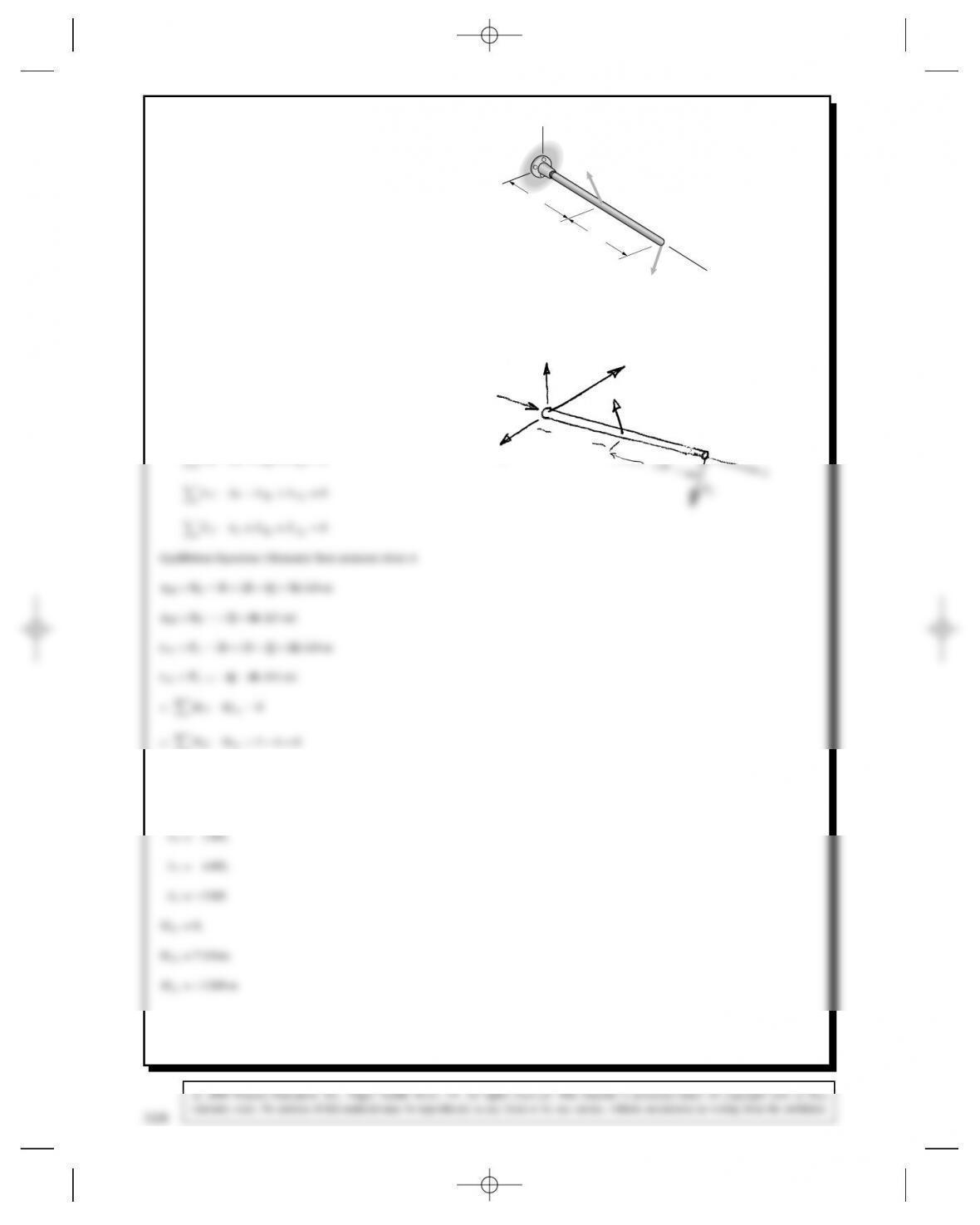
Problem 5.77 The bar AB has a built-in support at A
and is loaded by the forces
FBD2iC6jC3k(kN),
FCDi2jC2k(kN).
(a) Draw the free-body diagram of the bar.
(b) Determine the reactions at A.
Strategy: (a) Draw a diagram of the bar isolated from
its supports. Complete the free-body diagram of the bar
by adding the two external forces and the reactions
due to the built-in support (see Table 5.2). (b) Use the
scalar equilibrium equations (5.16)–(5.21) to determine
the reactions.
FC
FB
A
C
x
B
1 m
1 m
z
y
Solution:
MADMAXiCMAYjCMAZk
(b) Equilibrium Eqns (Forces)
FX:AXCFBXCFCXD0
AX
AY
BC
FB
AZ
MA = MAX i + MAY j + MAZ K
1 m
318
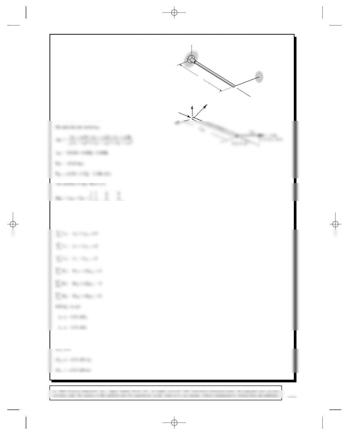
Problem 5.78 The bar AB has a built-in support at A.
The tension in cable BC is 8 kN. Determine the reactions
at A.
A
C
x
B
2 m
z
y
(3,0.5,–0.5)m
Solution:
MADMAxiCMAy jCMAz k
AX
AY
AZ
MA = MAX i + MAY j + MAZ K
Problem 5.79 The bar AB has a fixed support at A.
The collar at Bis fixed to the bar. The tension in the
rope BC is 300 lb. (a) Draw the free-body diagram of
the bar. (b) Determine the reactions at A.
y
B (6, 6, 2) ft
A
C (8, 0, 3) ft
z
x
Solution:
(a) The free-body diagram is shown.
These last equations can be written as
320
Problem 5.80 The bar AB has a fixed support at A.
The collar at Bis fixed to the bar. Suppose that you
don’t want the support at Ato be subjected to a couple
of magnitude greater than 3000 ft-lb. What is the largest
allowable tension in the rope BC?
y
B (6, 6, 2) ft
Solution: See the solution to Problem 5.79. The magnitude of the
couple at Acan be expressed in terms of the tension in the rope as
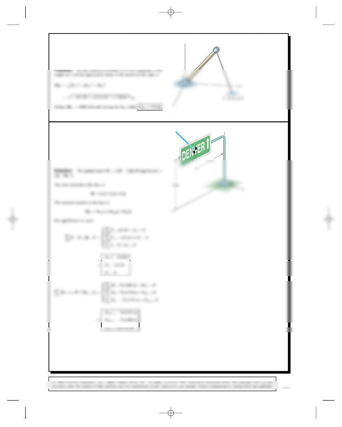
Problem 5.81 The total force exerted on the highway
sign by its weight and the most severe anticipated winds
is FD2.8i1.8j(kN). Determine the reactions at the
fixed support.
y
F
x
8 m
Solution: The applied load is FD⊲2.8i1.8j⊳kN applied at rD
⊲8jC8k⊳m
RDOxiCOyjCOzk
The moment reaction at the base is
Problem 5.82 The tension in cable AB is 800 lb.
Determine the reactions at the fixed support C.
y
4 ft
C
Solution: The force in the cable is
FD800 lb 2i4jk
p21
322
Problem 5.83 The tension in cable AB is 24 kN.
Determine the reactions in the built-in support D.
2 m
C
A
2 m
The force equations of equilibrium are
The corresponding scalar equations are
OYD19.60 kN,
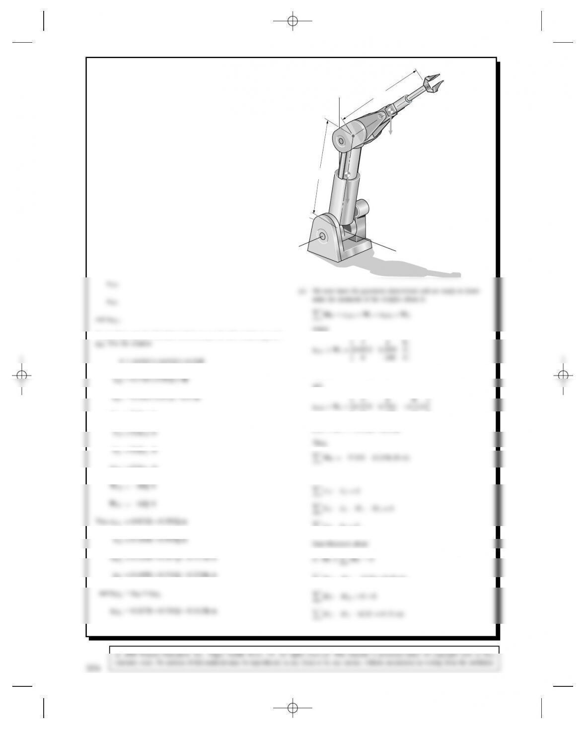
Problem 5.84 The robotic manipulator is stationary
and the yaxis is vertical. The weights of the arms AB and
BC act at their midpoints. The direction cosines of the
centerline of arm AB are cos xD0.174, cos yD0.985,
cos zD0, and the direction cosines of the centerline
of arm BC are cos xD0.743, cos yD0.557, cos zD
0.371. The support at Abehaves like a built-in support.
(a) What is the sum of the moments about Adue to
the weights of the two arms?
(b) What are the reactions at A?
x
y600 mm
600 mm
200 N
C
B
A
z
160 N
Solution: Denote the center of mass of arm AB as D1and that of
BC as D2. We need
To get these, use the direction cosines to get the unit vectors eAB and
rAD1D0.3eAB m
rBD2D0.3eBC m
where
0160 0
rAD2ðW2D17.81i52.37k
(b) Equilibrium Eqns
324
5.84 (Continued)
W2
W1
MA
MA = MAXi + MAYj + MAZk
W1 = 200 N
W2 = 160 N
D1
AY
AZ
AX
C
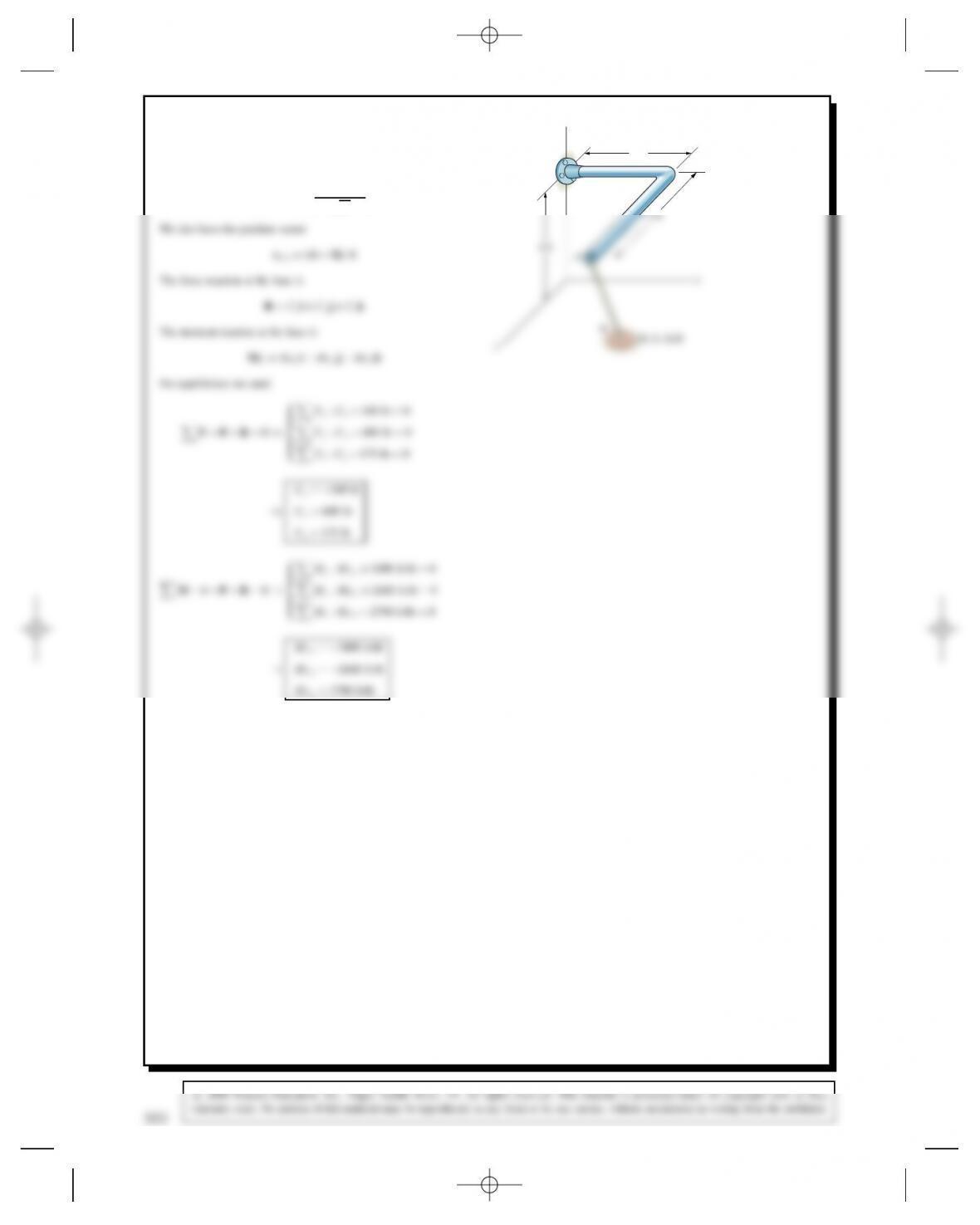
Problem 5.85 The force exerted on the grip of the
exercise machine is FD260i130j(N). What are the
reactions at the built-in support at O?
x
y
z
O
F
150
mm
200
mm
250
mm
Solution:
MODMOx iCMOy jCMOzk
rOP D0.25iC0.2j0.15k
MOXD19.5 (N-m)
P
F = 260 i – 130 j (N)
y
OX
OY
MO
0.15
m
326
c
2008 Pearson Education, Inc., Upper Saddle River, NJ. All rights reserved. This material is protected under all copyright laws as they
currently exist. No portion of this material may be reproduced, in any form or by any means, without permission in writing from the publisher.
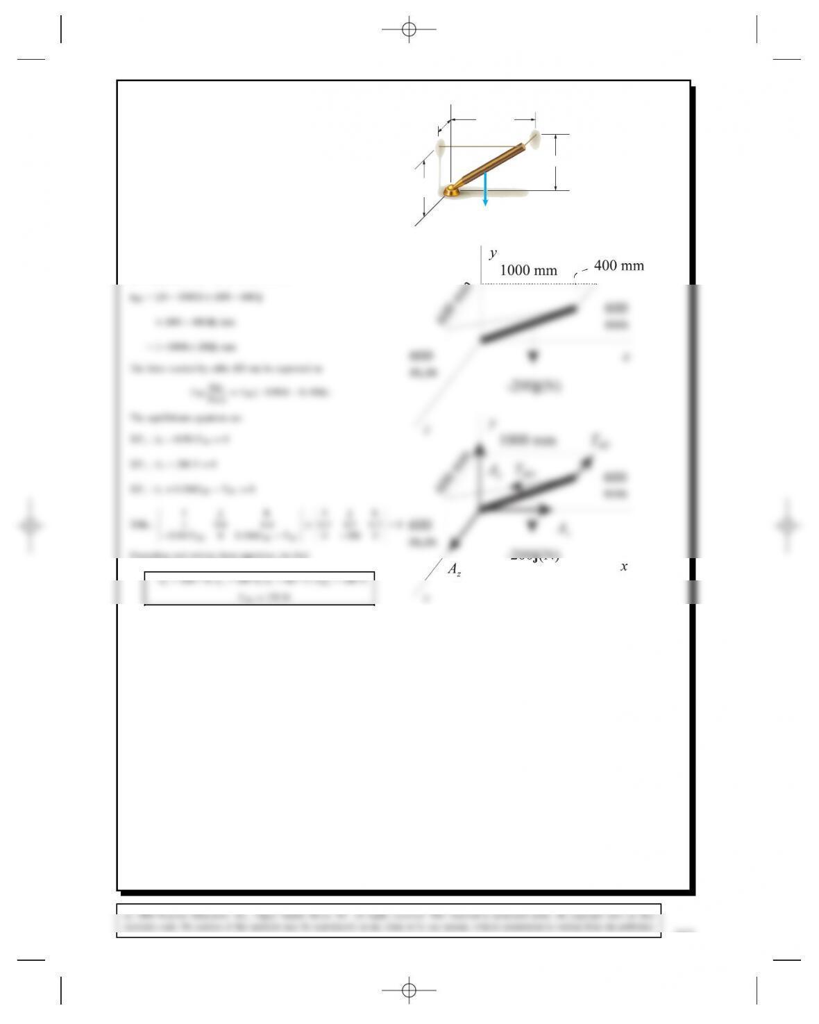
Problem 5.86 In Active Example 5.7, suppose that
cable BD is lengthened and the attachment point D
moved form (0, 600, 400) mm to (0, 600, 600) mm.
(The end Bof bar AB remains where it is.) Draw a
sketch of the bar and its supports showing cable BD in
its new position. Draw the free-body diagram of the bar
and apply equilibrium to determine the tensions in the
cables and the reactions at A.x
y
z
1000 mm
600 mm
C
B
⫺200j (N)
400
mm
600
mm
D
A
Solution: The sketch and free-body diagram are shown.
We must express the force exerted on the bar by cable BD in terms of
its components. The vector from Bto Dis
Expanding and solving these equations, we find


