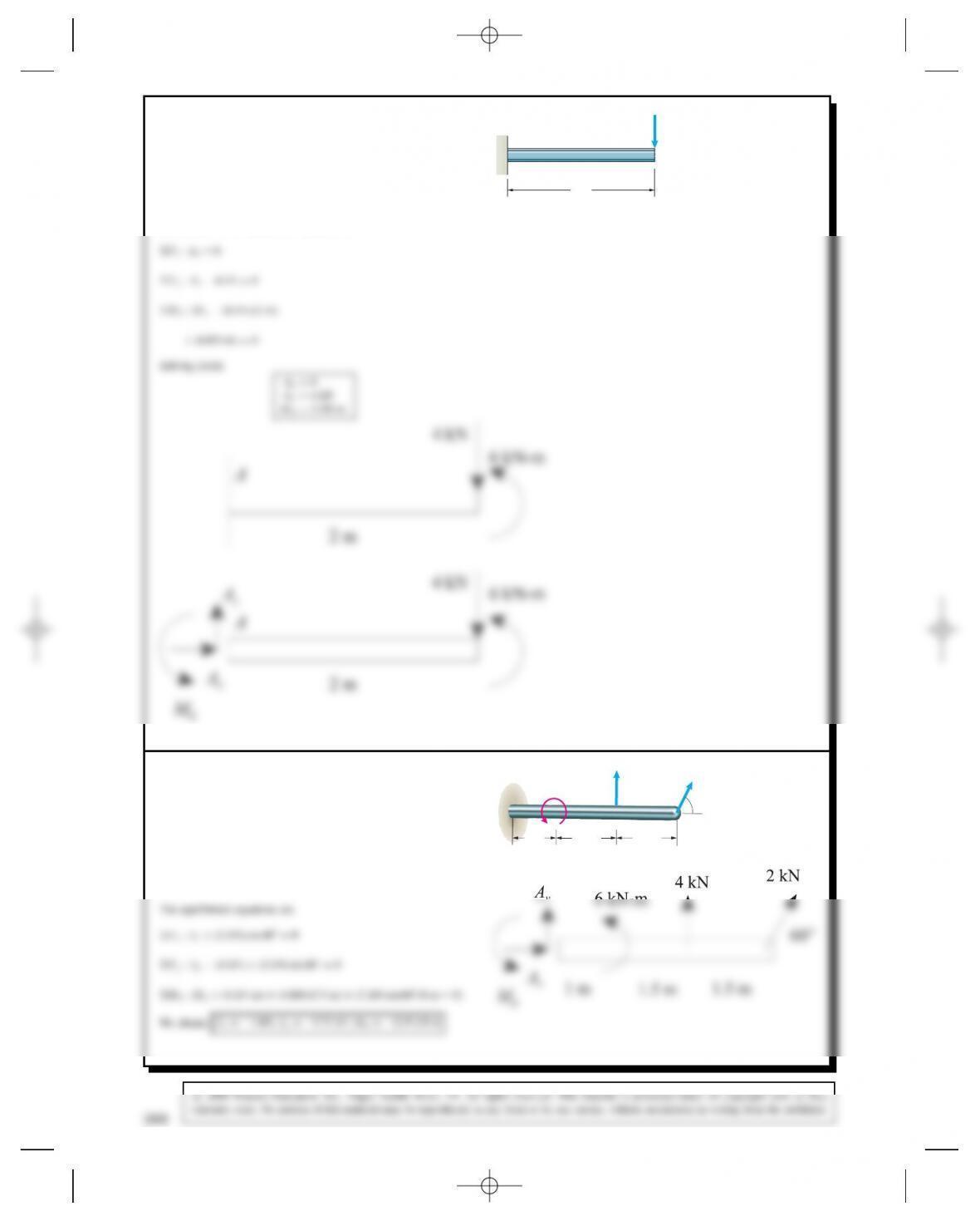
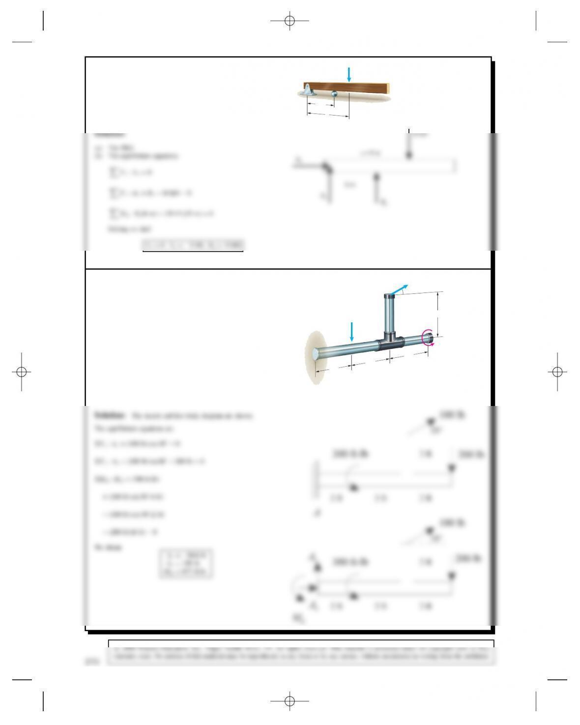
Problem 5.1 In Active Example 5.1, suppose that the
beam is subjected to a 6kN-m counterclockwise couple
at the right end in addition to the 4-kN downward force.
Draw a sketch of the beam showing its new loading.
Draw the free-body diagram of the beam and apply the
equilibrium equations to determine the reactions at A.
4 kN
2 m
A
Solution: The equilibrium equations are
Problem 5.2 The beam has a fixed support at Aand is
loaded by two forces and a couple. Draw the free-body
diagram of the beam and apply equilibrium to determine
the reactions at A.
2 kN
4 kN
60⬚
A6 kN-m
1.5 m
1.5 m
1 m
Solution: The free-body diagram is drawn.
268
Problem 5.3 The beam is subjected to a load FD
400 N and is supported by the rope and the smooth
surfaces at Aand B.
(a) Draw the free-body diagram of the beam.
(b) What are the magnitudes of the reactions at A
and B?
F
30°
45°
AB
1.2 m 1.5 m 1 m
Solution:
CMAD0: 1.2T2.7⊲400⊳C3.7Bcos 30°D0
Solving, we get
AD271 N
BD383 N
TD124 N
y
F
A
Problem 5.4 (a) Draw the free-body diagram of the
beam. (b) Determine the tension in the rope and the
reactions at B.
5 ft 9 ft
30⬚
30⬚
B
A
600 lb
Problem 5.5 (a) Draw the free-body diagram of the
60-lb drill press, assuming that the surfaces at Aand B
are smooth.
Solution: The system is in equilibrium.
(a) The free body diagram is shown.
270
Problem 5.6 The masses of the person and the diving
board are 54 kg and 36 kg, respectively. Assume that
they are in equilibrium.
1.2 m
Solution:
(a)
AYD1.85 kN
AY
AX
BYWP
WD
1.2 m
2.4 m
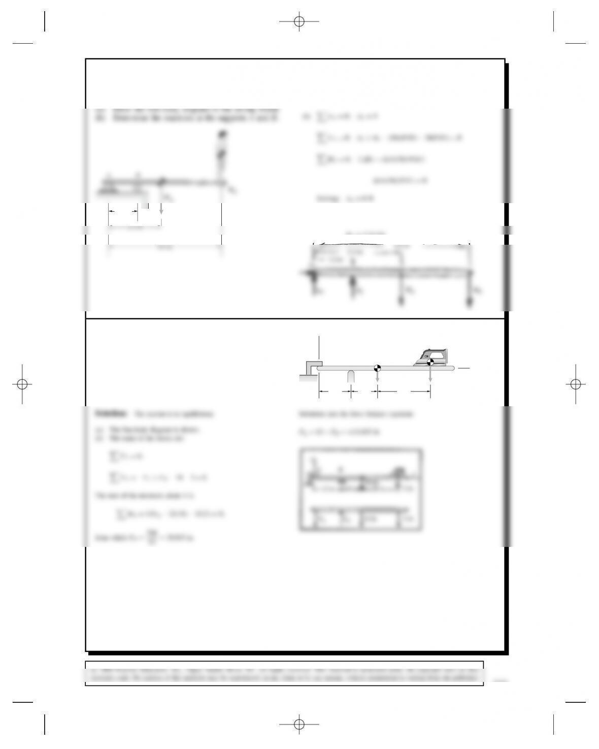
Problem 5.7 The ironing board has supports at Aand
Bthat can be modeled as roller supports.
(a) Draw the free-body diagram of the ironing board.
(b) Determine the reactions at Aand B.
y
x
A
10 lb 3 lb
B
12 in 10 in 20 in
Problem 5.8 The distance xD9m.
(a) Draw the free-body diagram of the beam.
(b) Determine the reactions at the supports.
10 kN
B
A
x
6 m
(b) The equilibrium equations
Fx:AxD0
Fy:AyCBy10 kN D0
MA:By⊲6m⊳⊲10 kN⊳⊲9m⊳D0
Solving we find
AxD0,A
yD5kN,B
yD15 kN
6 m
Ax
AyBy
Problem 5.9 In Example 5.2, suppose that the 200-lb
downward force and the 300 ft-lb counterclockwise
couple change places; the 200-lb downward force acts
at the right end of the horizontal bar, and the 300 ft-lb
counterclockwise couple acts on the horizontal bar 2 ft
to the right of the support A. Draw a sketch of the object
showing the new loading. Draw the free-body diagram
of the object and apply the equilibrium equations to
determine the reactions at A.2 ft
2 ft
2 ft
300 ft-lb
2 ft
100 lb
200 lb
A
30
272
Problem 5.10 (a) Draw the free-body diagram of the
beam.
(b) Determine the reactions at the supports.
100 lb 400 lb
B
A
900 ft-lb
3 ft 4 ft 3 ft 4 ft
The sum of the moments about Ais
MAD3⊲100⊳C900 7⊲400⊳C11FBD0.
From which FBD2200
11 D200 lb
Substitute into the force balance equation to obtain
FAD300 FBD100 lb
3 ft
3 ft
900 ft lb
4 ft 4 ft
FAFB
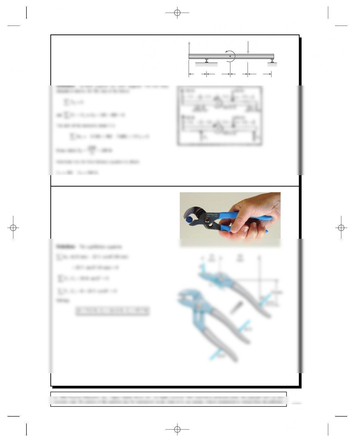
Problem 5.11 The person exerts 20-N forces on the
pliers. The free-body diagram of one part of the pliers
is shown. Notice that the pin at Cconnecting the two
parts of the pliers behaves like a pin support. Determine
the reactions at Cand the force Bexerted on the pliers
by the bolt.
C
50 mm
45⬚
80
mm
25
mm
C
Cy
Cx
B
Solution: The equilibrium equations
MC:B⊲25 mm⊳20 N cos 45°⊲80 mm⊳
20 N sin 45°⊲50 mm⊳D0
Fx:Cx20 N sin 45°D0
Fy:CyB20 N cos 45°D0
Solving:
Problem 5.12 (a) Draw the free-body diagram of the
beam.
(b) Determine the reactions at the pin support A.
30⬚
AB
2 kN-m
8 kN 8 kN
600
mm
500
mm
600
mm
600
mm
(b) The equilibrium equations
MA:⊲8kN⊳⊲0.6m⊳C⊲8kN⊳⊲1.1m⊳2 kNm
Bcos 30°⊲2.3m⊳D0
Fx:AxBsin 30°D0
Fy:Ay8kNC8kNBcos 30°D0
Solving
AxD0.502 kN,A
yD0.870 kN,BD1.004 kN
Ax
Ay
B
Problem 5.13 (a) Draw the free-body diagram of the
beam.
(b) Determine the reactions at the supports.
A
y
6 m
8 m
12 m
Bx
40 kN
274
Problem 5.14 (a) Draw the free-body diagram of the
beam.
(b) If FD4 kN, what are the reactions at Aand B?
A2 kN-m
B
F0.2 m
0.4 m
0.3 m
0.3 m
0.2 m
Solution:
Ax
2 kN-m
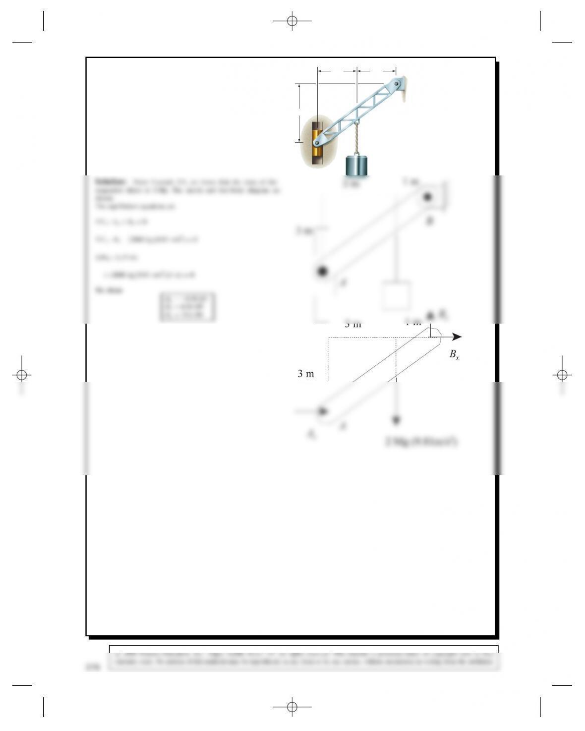
Problem 5.15 In Example 5.3, suppose that the attach-
ment point for the suspended mass is moved toward
point Bsuch that the horizontal distance from Ato
the attachment point increases from 2 m to 3 m. Draw
a sketch of the beam AB showing the new geometry.
Draw the free-body diagram of the beam and apply the
equilibrium equations to determine the reactions at A
to B.
2 m
A
B
3 m
2 m
276
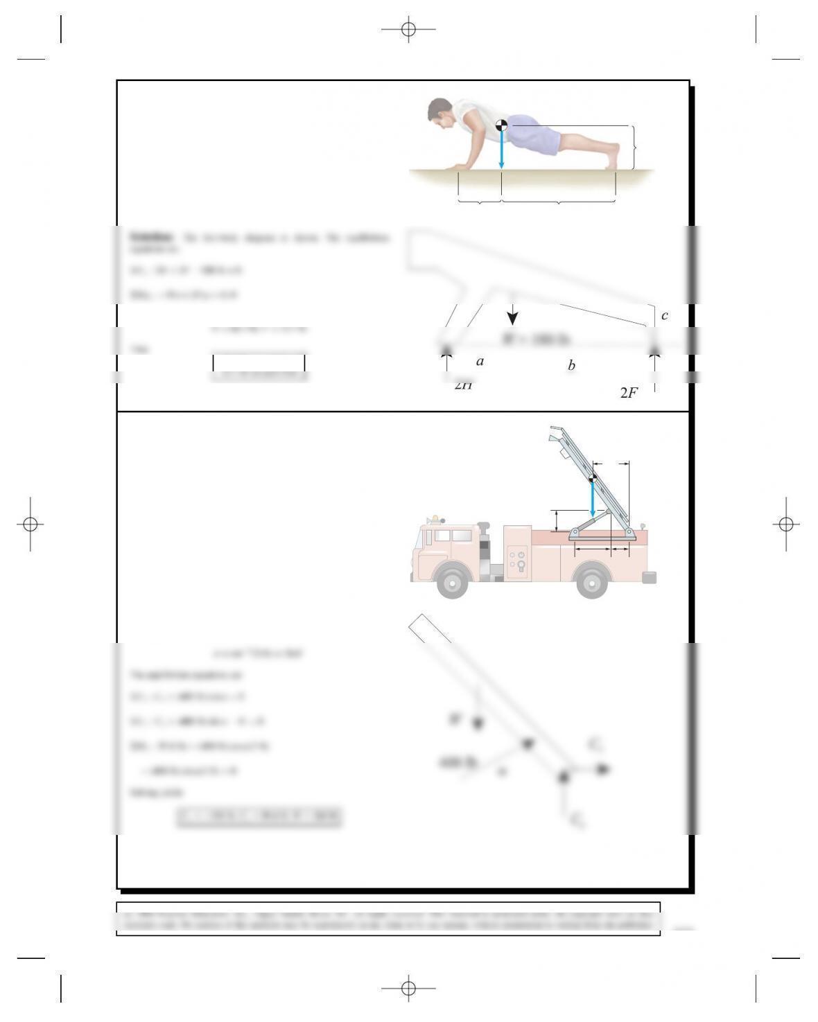
Problem 5.16 A person doing push-ups pauses in the
position shown. His 180-lb weight Wacts at the point
shown. The dimensions a=15in,b= 42 in, and c=16
in. Determine the normal force exerted by the floor on
each of his hands and on each of his feet. W
ab
c
We find that
66.3 lb on each hand
Problem 5.17 The hydraulic piston AB exerts a 400-lb
force on the ladder at Bin the direction parallel to the
piston. Determine the weight of the ladder and the reac-
tions at C.
AB
C
3 ft
6 ft 3 ft
6 ft
W
Solution: The free-body diagram of the ladder is shown.
The angle between the piston AB and the horizontal is
Problem 5.18 Draw the free-body diagram of the
structure by isolating it from its supports at Aand E.
Determine the reactions at Aand E.
C
D
BA
100 lb
E
400 lb
200 ft-lb
2 ft
1 ft
1 ft
2 ft 2 ft 2 ft
Solution: The free-body diagram is shown.
The equilibrium equations are
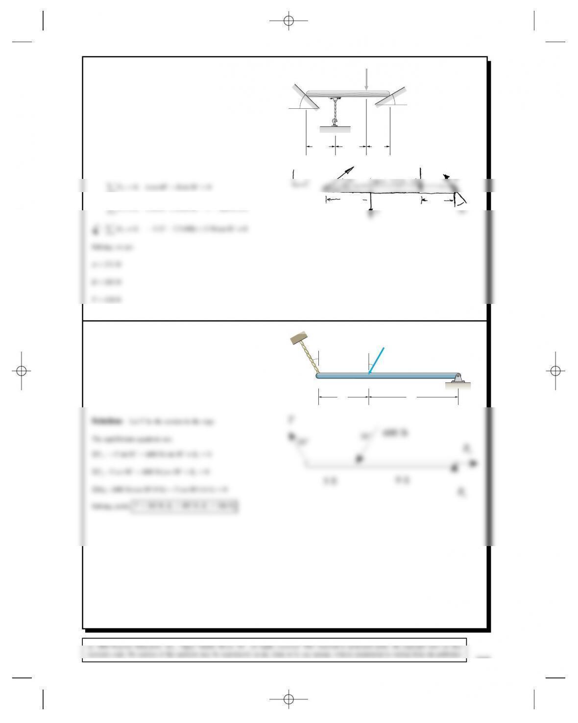
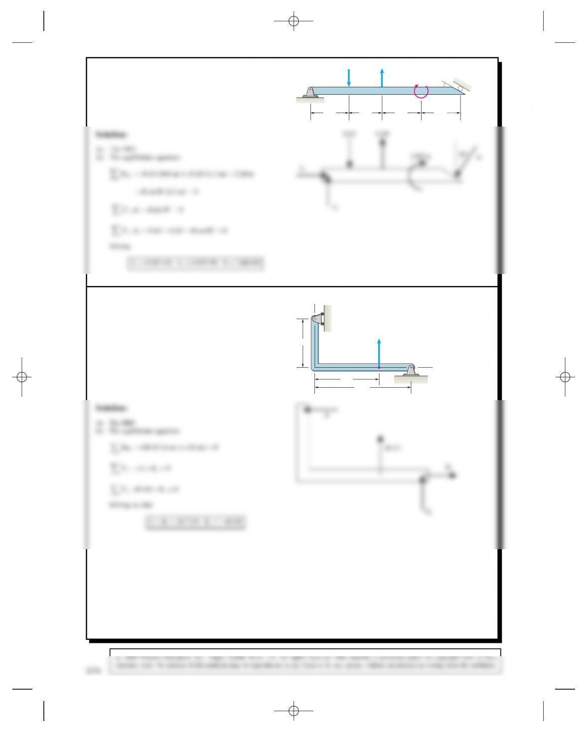
Problem 5.19 (a) Draw the free-body diagram of the
beam.
(b) Determine the tension in the cable and the reactions
at A.A
30 in 800 lb
BC
30 in 30 in
30°
Solution:
TT
278
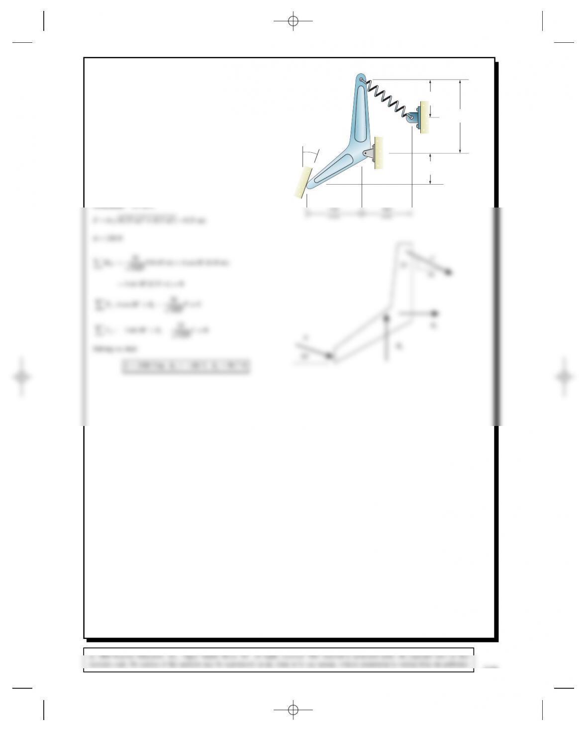
Problem 5.20 The unstretched length of the spring CD
is 350 mm. Suppose that you want the lever ABC to
exert a 120-N normal force on the smooth surface at A.
Determine the necessary value of the spring constant k
and the resulting reactions at B.
20⬚
B
A
C
k
D450
mm
180
mm
230
mm
Solution: We have
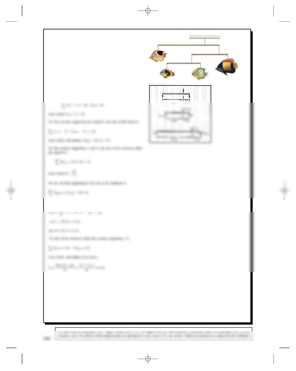
Problem 5.21 The mobile is in equilibrium. The fish
Bweighs 27 oz. Determine the weights of the fish A,C,
and D. (The weights of the crossbars are negligible.) 12 in 3 in
2 in6 in
2 in7 in
A
C
D
B
Solution: Denote the reactions at the supports by FAB,FCD, and
FBCD as shown. Start with the crossbar supporting the weights C
and D. The sum of the forces is
CD
FCD
280
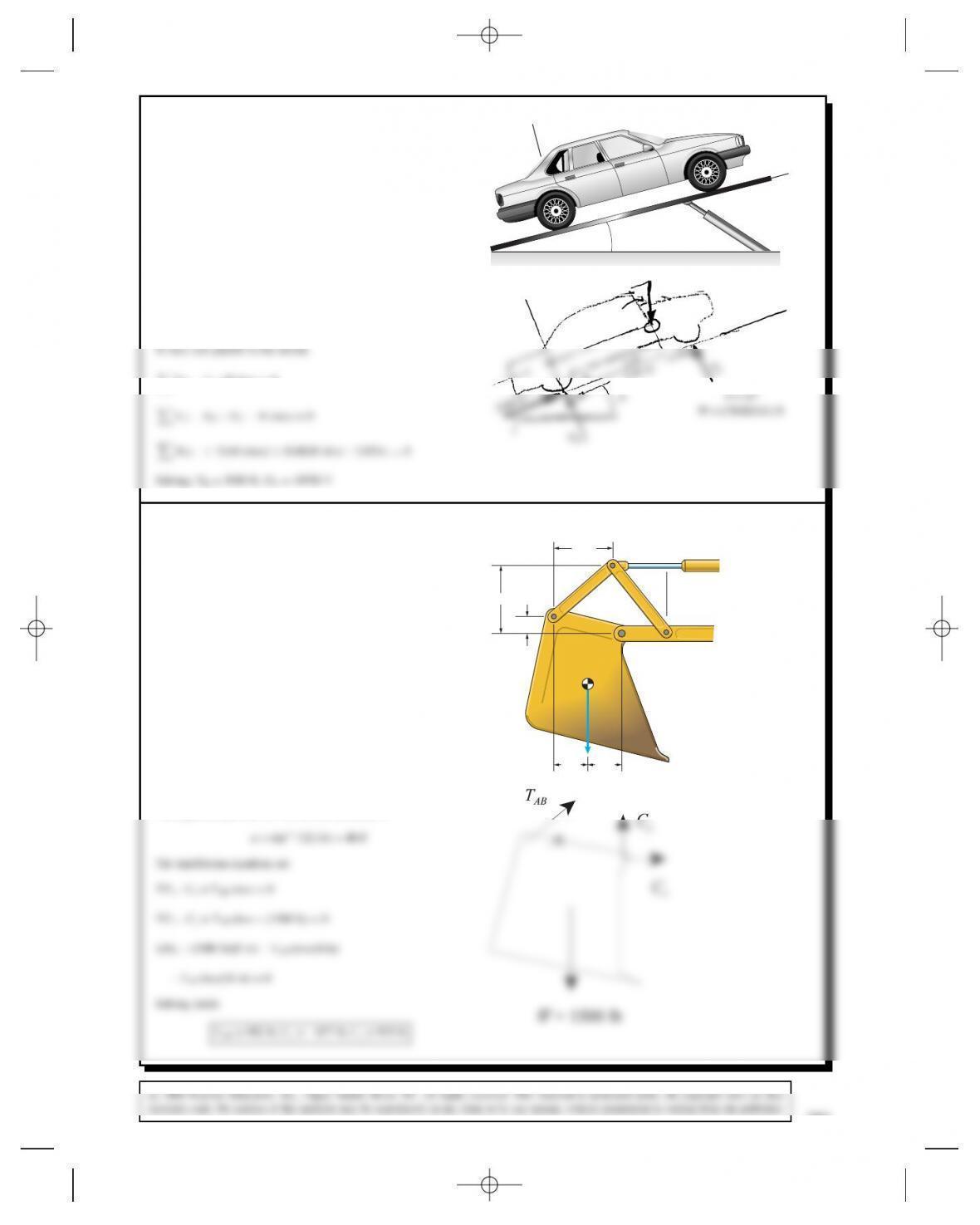
Problem 5.22 The car’s wheelbase (the distance
between the wheels) is 2.82 m. The mass of the car is
1760 kg and its weight acts at the point xD2.00 m,
yD0.68 m. If the angle ˛D15°, what is the total
normal force exerted on the two rear tires by the sloped
ramp?
y
x
α
Solution: Split Winto components:
Wcos ˛acts ?to the incline
FY:NRCNFWcos ˛D0
MR:⊲2⊳⊲W cos ˛⊳ C⊲0.68⊳W sin ˛C2.82NFD0
Solving: NRD5930 N, NFD10750 N
0.68 m
fNR
α
y
x
W
W = (1760X9.81) N
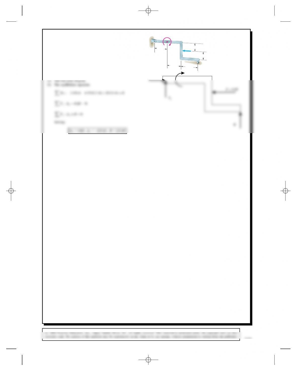
Problem 5.23 The link AB exerts a force on the bucket
of the excavator at Athat is parallel to the link. The
weight W= 1500 lb. Draw the free-body diagram of the
bucket and determine the reactions at C. (The connection
at Cis equivalent to a pin support of the bucket.)
8 in
14 in
8 in
W
CD
A
16 in
4 in
B
Solution: The free-body diagram is shown.
The angle between the link AB and the horizontal is
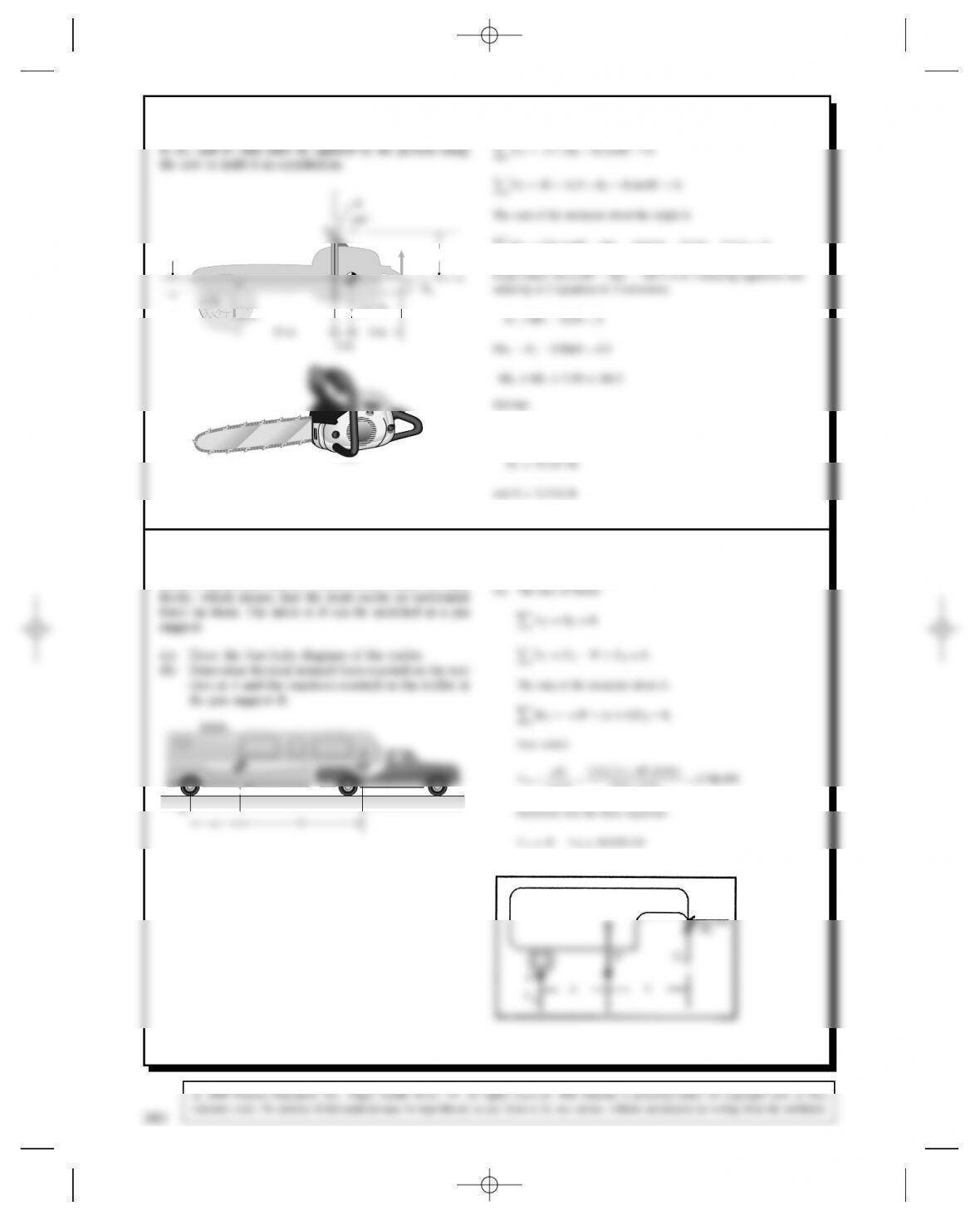
Problem 5.24 The 14.5-lb chain saw is subjected to
the loads at Aby the log it cuts. Determine the reactions
Solution: The sum of the forces are
FXD5CBXRcos 60°D0.
BXD11.257 lb,
Problem 5.25 The mass of the trailer is 2.2 Mg (mega-
grams). The distances aD2.5 m and bD5.5 m. The
truck is stationary, and the wheels of the trailer can turn
Solution:
(a) The free body diagram is shown.
ab
A
282
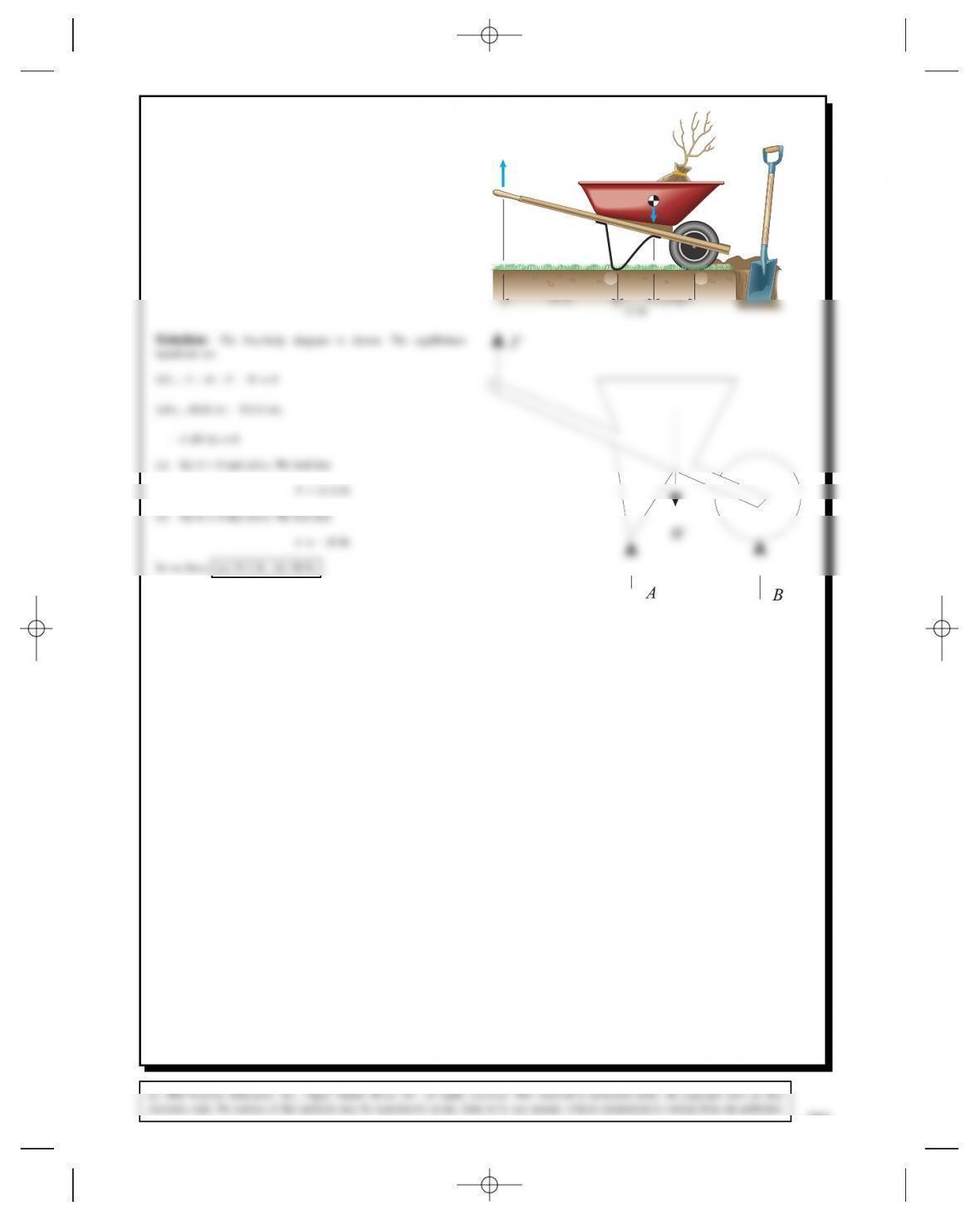
Problem 5.26 The total weight of the wheelbarrow
and its load is W= 100 lb. (a) What is the magnitude of
the upward force Fnecessary to lift the support at Aoff
the ground? (b) What is the magnitude of the downward
force necessary to raise the wheel off the ground?
B
W
A
F
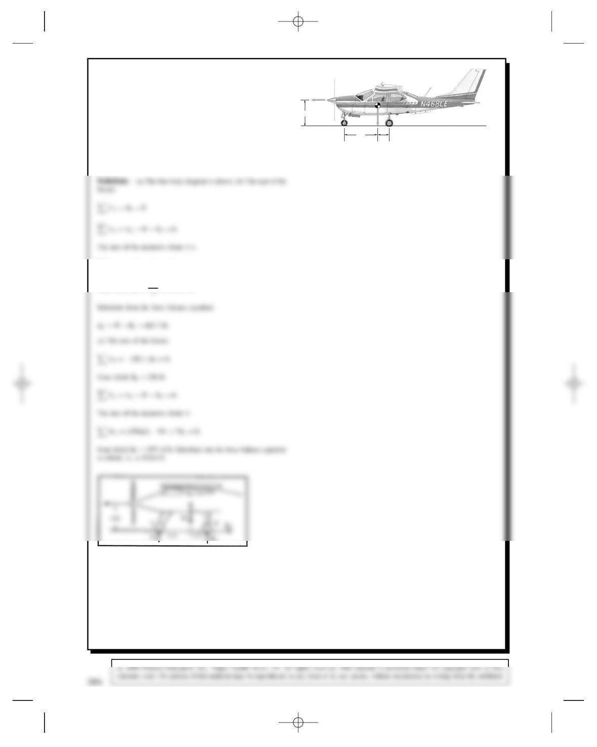
Problem 5.27 The airplane’s weight is WD2400 lb.
Its brakes keep the rear wheels locked. The front (nose)
wheel can turn freely, and so the ground exerts no hori-
zontal force on it. The force Texerted by the airplane’s
propeller is horizontal.
(a) Draw the free-body diagram of the airplane. Deter-
mine the reaction exerted on the nose wheel and
the total normal reaction on the rear wheels
(b) when TD0,
(c) when TD250 lb.
W
T
B
A
5 ft
4 ft
2 ft
MAD5WC7BYD0,
from which BYD5W
284
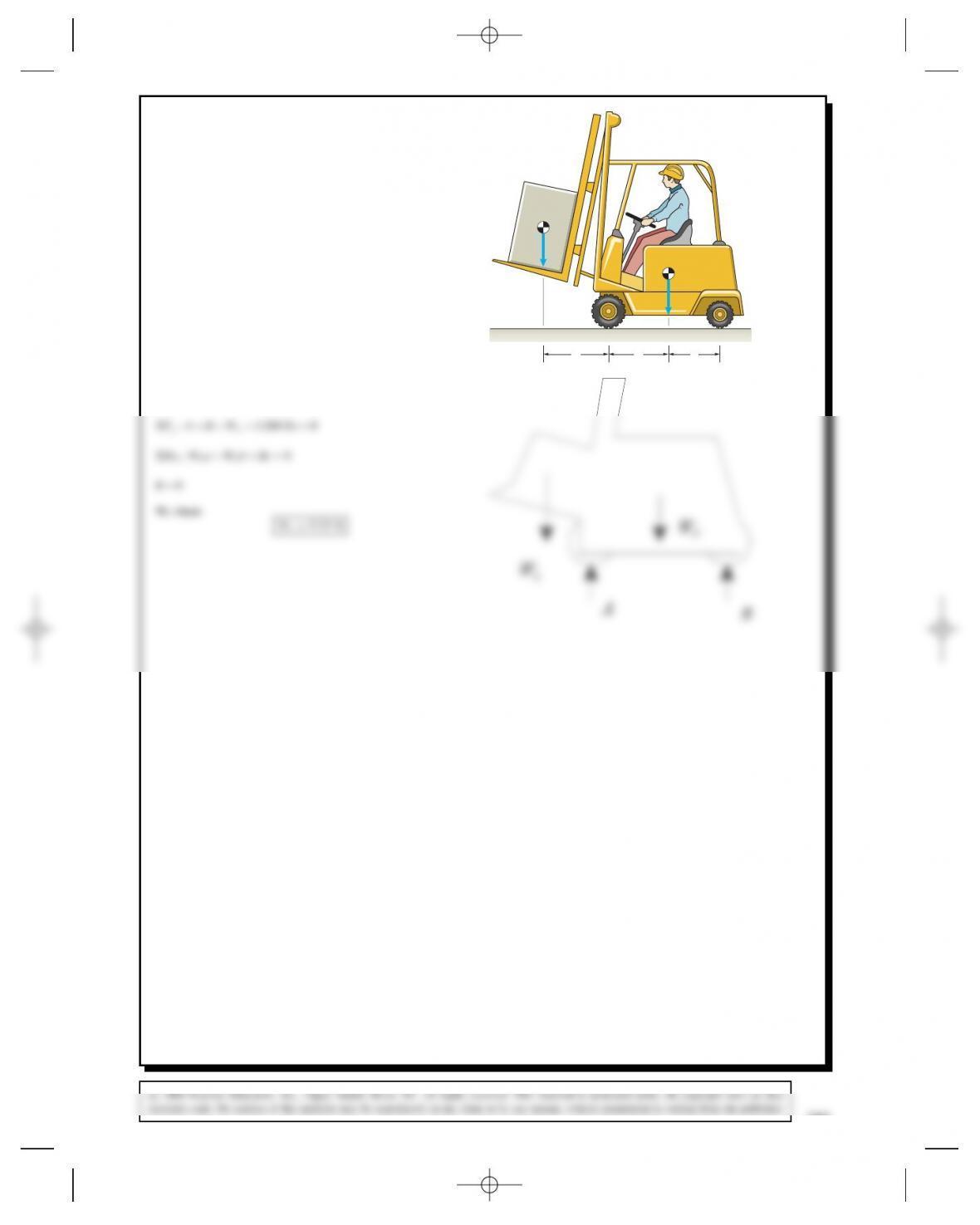
Problem 5.28 A safety engineer establishing limits on
the load that can be carried by a forklift analyzes the
situation shown. The dimensions are a= 32 in, b=30
in, and c= 26 in. The combined weight of the forklift and
operator is WF= 1200 lb. As the weight WLsupported
by the forklift increases, the normal force exerted on the
floor by the rear wheels at Bdecreases. The forklift is
on the verge of tipping forward when the normal force
at Bis zero. Determine the value of WLthat will cause
this condition.
abc
WF
BA
WL
Solution: The equilibrium equations and the special condition for
this problem are
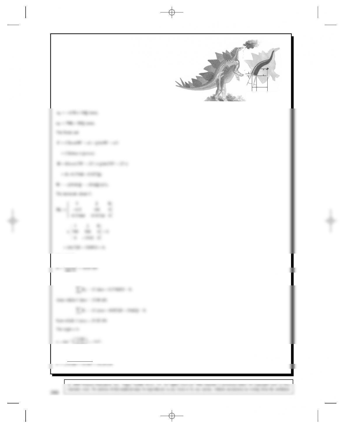
Problem 5.29 Paleontologists speculate that the ste-
gosaur could stand on its hind limbs for short periods
to feed. Based on the free-body diagram shown and
assuming that mD2000 kg, determine the magnitudes
of the forces Band Cexerted by the ligament –muscle
brace and vertebral column, and determine the angle ˛.
mg
B
22°
α
C
160
mm
580
mm
415
mm
790
mm
Solution: Take the origin to be at the point of application of the
force C. The position vectors of the points of application of the forces
Band Ware:
from which
444.72 D34.85 kN.
The sums of the forces:
51.93 D14.1°.
The magnitude of C,
286
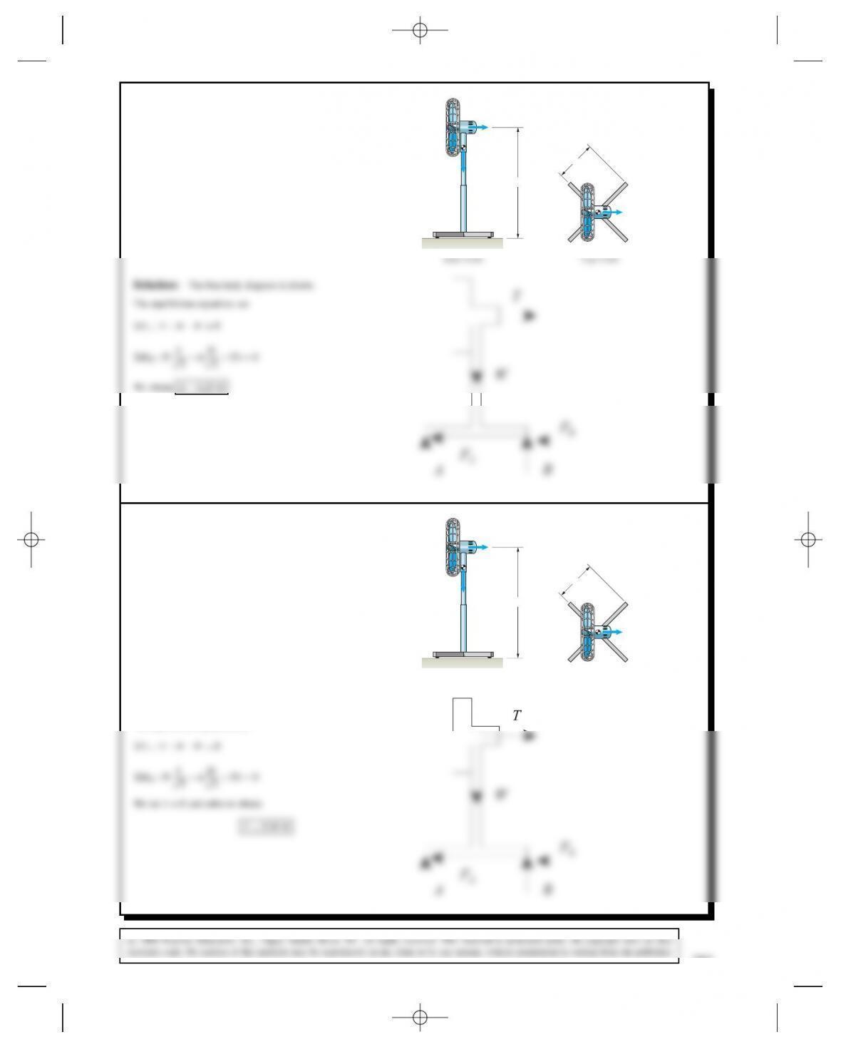
Problem 5.30 The weight of the fan is WD20 lb. Its
base has four equally spaced legs of length bD12 in.
Each leg has a pad near the end that contacts the floor
and supports the fan. The height hD32 in. If the fan’s
blade exerts a thrust TD2 lb, what total normal force
is exerted on the two legs at A?
h
b
T
W
AB
T
Problem 5.31 The weight of the fan is WD20 lb. Its
base has four equally spaced legs of length bD12 in.
Each leg has a pad near the end that contacts the floor
and supports the fan. The height hD32 in. As the thrust
Tof the fan increases, the normal force supported by the
two legs at Adecreases. When the normal force at Ais
zero, the fan is on the verge of tipping over. Determine
the value of Tthat will cause this condition.
h
b
T
W
Side View
AB
Top View
T
Solution: The free-body diagram is shown.
The equilibrium equations are