299
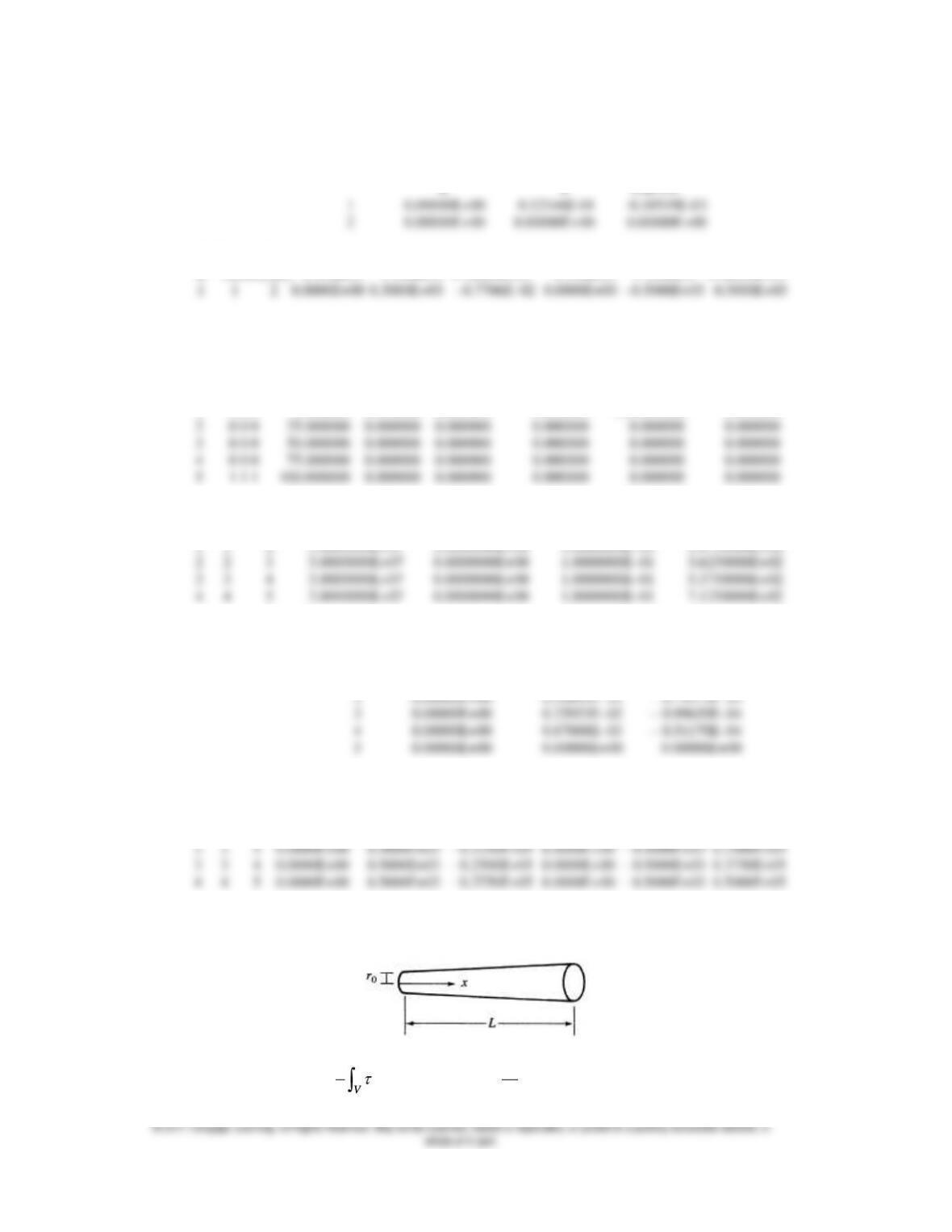
K NODE(I,K) E(K) G(K) A(K) XI(K)
1 1 2 3.0000000E+07 0.0000000E+00 1.0000000E–01 4.5000000E+02
NODE DISPLACEMENTS Z-ROTATION
ELEMENTS
K NODE(I,K) X-FORCE Y-FORCE Z-MOMENT X-FORCE Y-FORCE Z-MOMENT
NUMBER OF ELEMENTS = 4
NUMBER OF NODES = 5
NODE POINTS
K IFIX XC(K) YC(K) ZC(K) FORCE(1,K) FORCE(2,K) FORCE(3,K)
1 0 0 0 0.000000 0.000000 0.000000 0.000000 500.000000 0.000000
ELEMENTS
K NODE(I,K) E(K) G(K) A(K) XI(K)
1 1 2 3.0000000E+07 0.0000000E+00 1.0000000E–01 1.8750000E+02
NODE DISPLACEMENTS Z-ROTATION
X Y THETA
1 0.00000E+00 0.97156E–02 – 0.17050E–03
ELEMENTS
K NODE X-FORCE Y-FORCE Z-MOMENT X-FORCE Y-FORCE Z-MOMENT
(1,K)
1 1 2 0.0000E+00 0.5000E+03 0.3812E –01 0.0000E+00 – 0.5000E+03 0.1250E+05
5.46
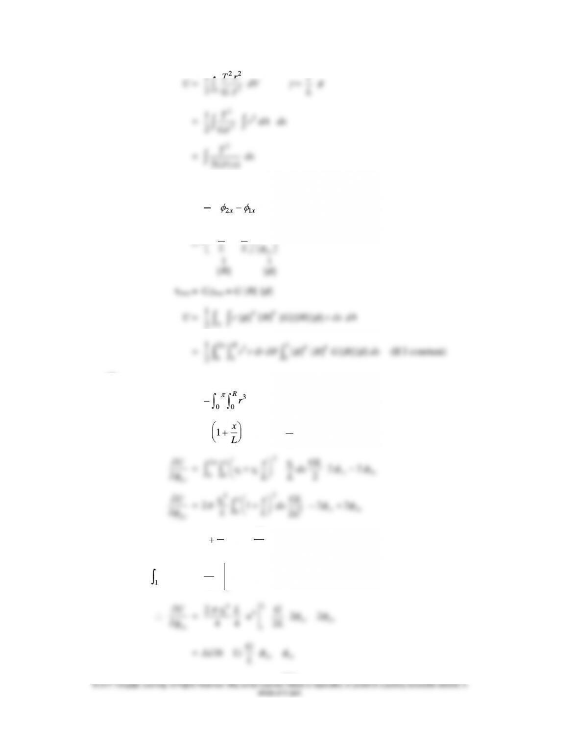
U =
1
2V
dV
=
Tr
J
= G
300
22
2
1
2V
r
GJ
r
L
=
22
2
1
2
Tr dA
GJ
dx
=
2
2 ( )
T
GJ x
dx
Now
=
r
L
21xx
1
|| ||
11
[ ] { }
x
rLL
B
max = G
max = G [B]
{}
U =
1{ } [ ] { }[ ]{ }
2
TT
Ar B G B r dx
dA
=
22
00
1
2
Rr
r dr d
0{ } [ ] [ ]{ }
LTT
B G B dx
(If J constant)
or
U =
23
00
1
2
Rr
dr d
0{ } [ ] [ ]{ }
LTT
B G B dx
r = r0
1x
L
dr =
0
r
L
dx
U
3
2
Lx
012
rGL
2x
2
01 – 2 2
2
xx
LL
L
Let u =
1x
L
, du =
dx
L
2
1
u3 L du =
2
4
1
4
uL
U
4
0
2
rL
2
4
G
21
xx
L
301
U
G
11
L
5.47
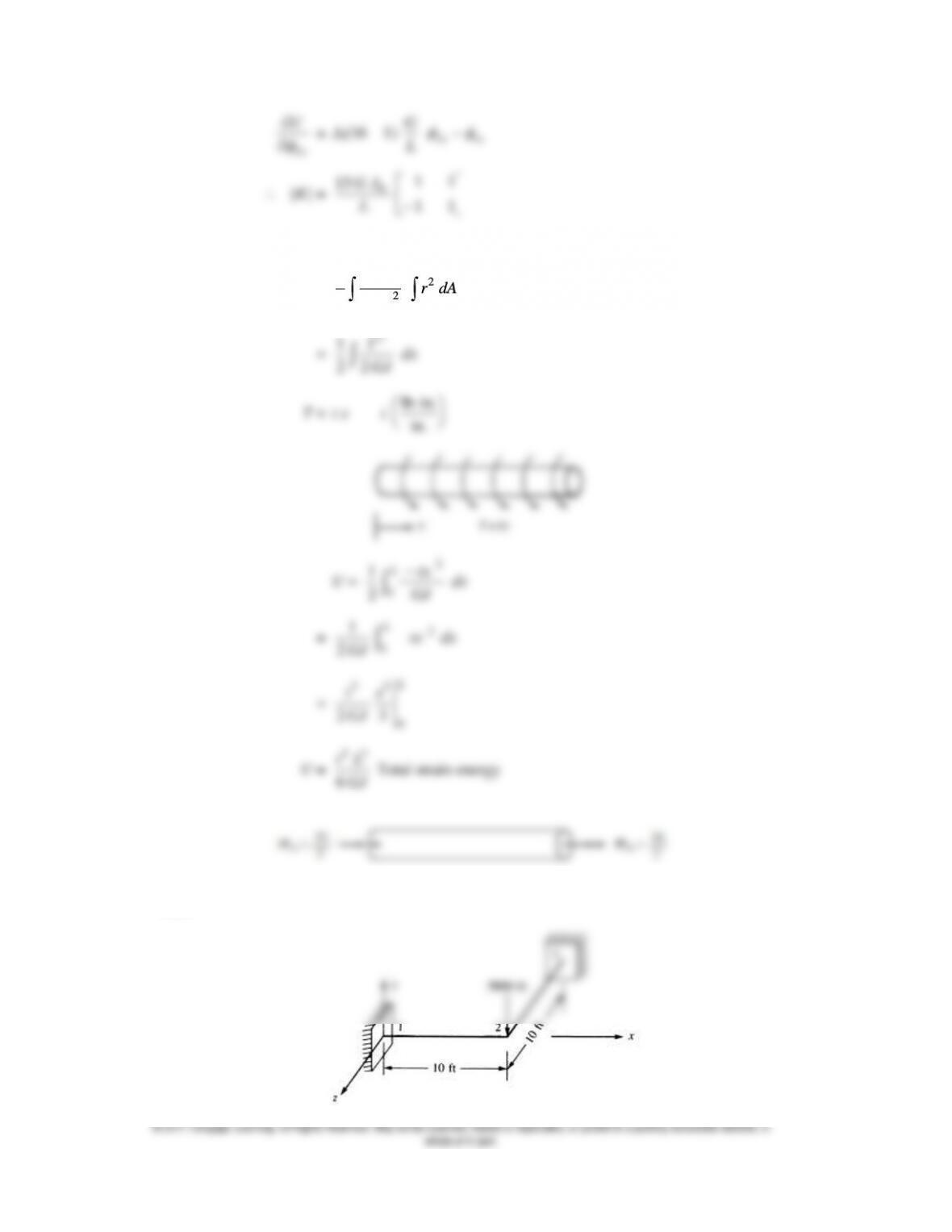
U =
22
2
1
22
Tr dA
GJ
dx
2
1
T
6
GJ
5.48
302
NUMBER OF ELEMENTS = 2
NUMBER OF NODES = 3
NODE POINTS
K IFIX XC(K) YC(K) ZC(K) FORCE(1,K) FORCE(2,K) FORCE(3,K)
1 1 1 1 0.0000000 0.000000 0.000000 0.000000 0.000000 0.000000
ELEMENTS
K NODE(I,K) E(K) XI(K) XJ(K) G(K)
1 1 2 3.0000000E+04 2.0000000E+02 1.0000000E+02 1.0000000E+04
NODE DISPLACEMENT THETA-X THETA-Z
1 0.00000E+00 0.00000E+00 0.00000E+00
ELEMENTS
K NODE Y-FORCE X-MOMENT Z-MOMENT Z-MOMENT Y-FORCE X-MOMENT
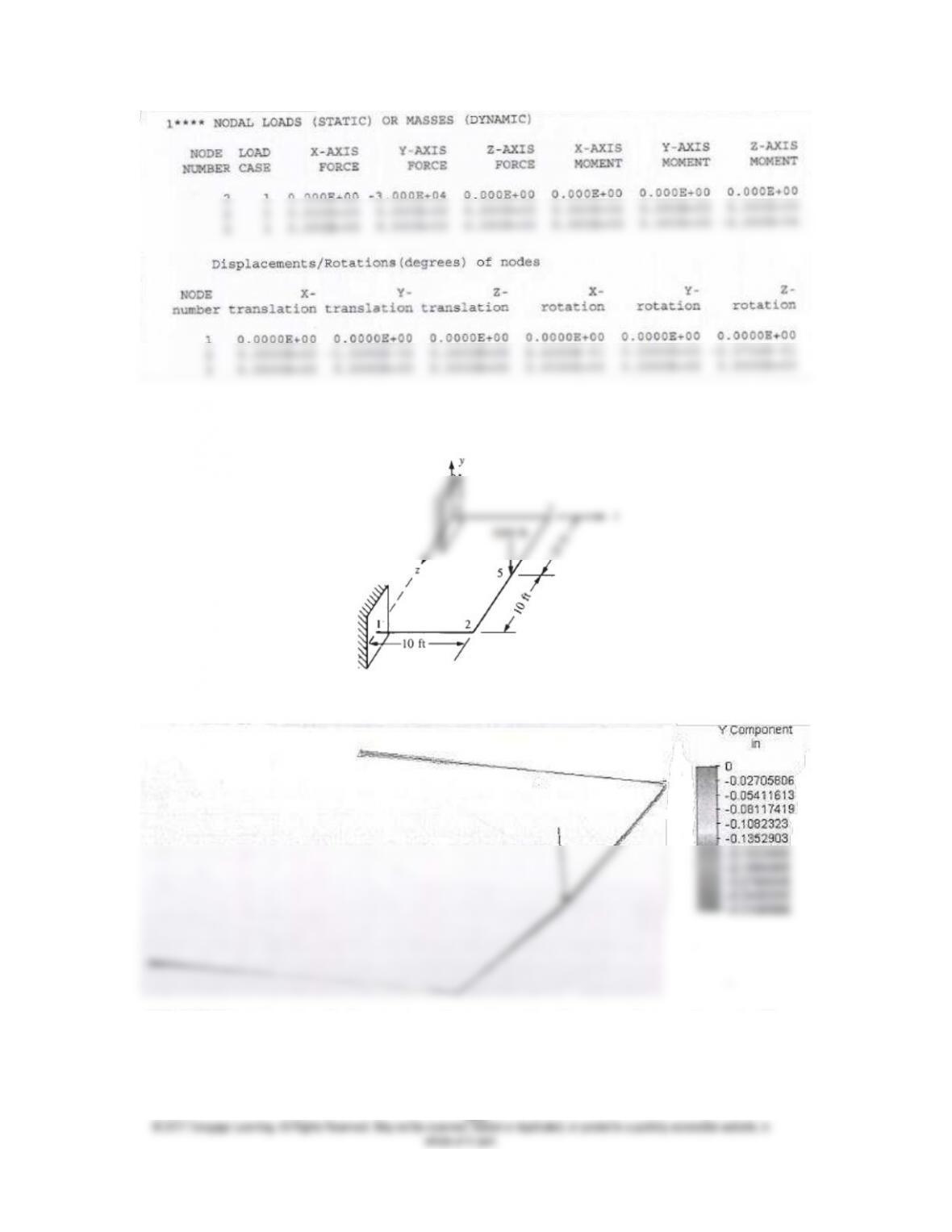
5.51
303
5.52
Figure P5–52
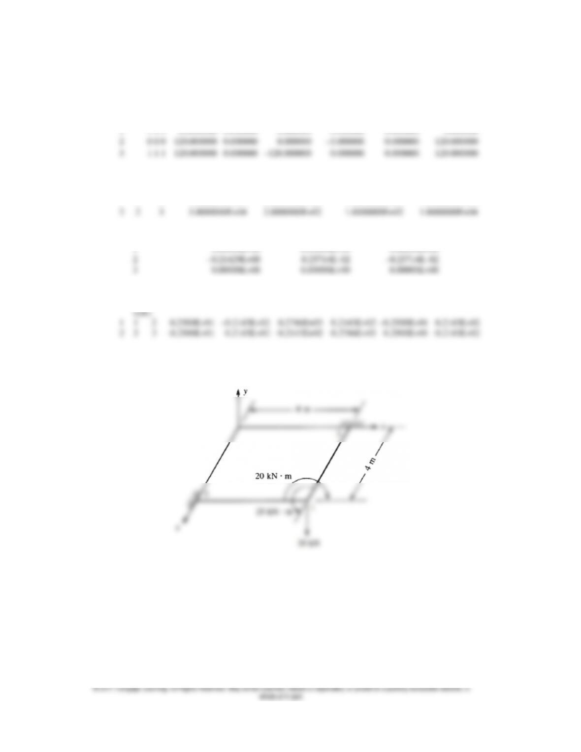
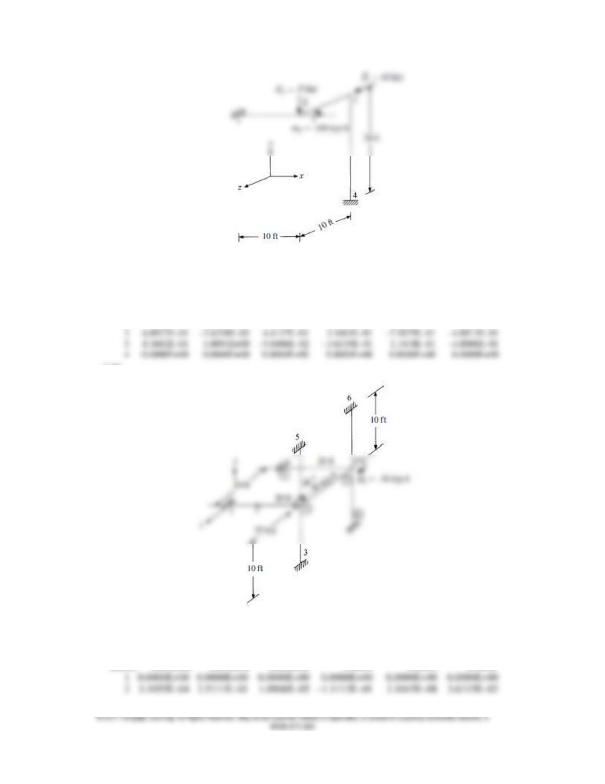
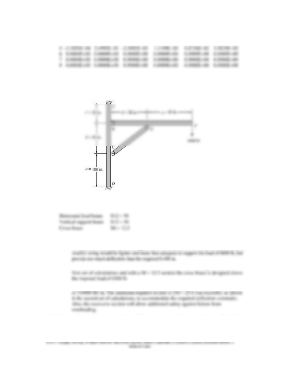
5.58-5.59 Determine the displacements and reactions for the space frames shown in Figures
P5–58 and P5–59. Let Ix = 100 in.4, Iy = 200 in.4, Iz = 1000 in.4, E = 30,000 ksi,
G = 10,000 ksi, and A = 100 in.2 for both frames.
304
Figure P5–58
Displacements/Rotations (degrees) of nodes
NODE X– Y– Z– X– Y– Z–
number translation translation translation rotation rotation rotation
1 0.0000E+00 0.0000E+00 0.0000E+00 0.0000E+00 0.0000E+00 0.0000E+00
5.59
Figure P5–59
Displacements/Rotations (degrees) of nodes
NODE X– Y– Z– X– Y– Z–
number translation translation translation rotation rotation rotation
305
3 0.0000E+00 0.0000E+00 0.0000E+00 0.0000E+00 0.0000E+00 0.0000E+00
4 0.0000E+00 0.0000E+00 0.0000E+00 0.0000E+00 0.0000E+00 0.0000E+00
5.60 Design a jib crane as shown in Figure P5–60 that will support a downward load of 6000 lb.
Choose a common structural steel shape for all members. Use allowable stresses of 0.66 Sy (Sy
is the yield strength of the material) in bending, and 0.60 Sy in tension.
FigureP5–60
All members A36 structural steel
The required maximum deflection governed the selection of the material section size, as
The force in the cross brace (21066 lbf) does not yield to buckling as shown in the
The horizontal load beam is designed to withstand above the imposed bending moment
5.61 Design the support members, AB and CD, for the platform lift shown in Figure P5-61. Select
a mild steel and choose suitable cross-sectional shapes with no more than a 4 : 1 ratio of
moments of inertia between the two principal directions of the cross section. You may
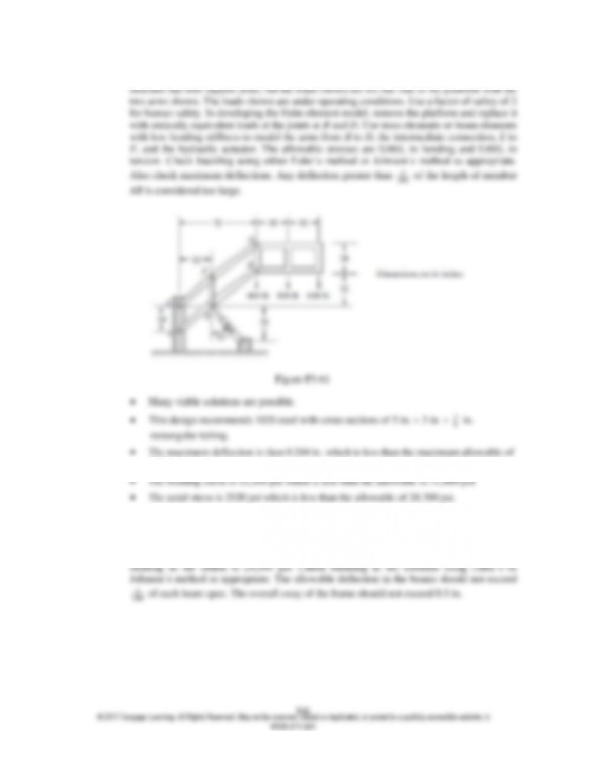
choose two different cross sections to make up each arm to reduce weight. The actual
360
0.25 in.
5.62 A two-story building frame is to be designed as shown in Figure P5-62. The members are all
to be I-beams with rigid connections. We would like the floor joists beams to have a 15-in.
depth and the columns to have a 10 in. width. The material is to be A36 structural steel. Two
horizontal loads and vertical loads are shown. Select members such that the allowable
360
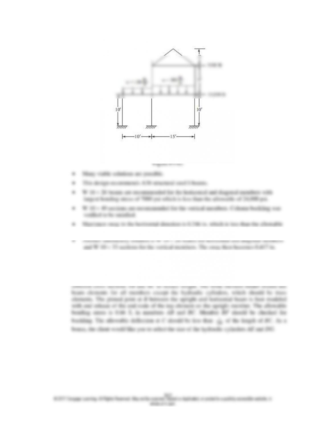
of 0.50 in.
5.63 A pulpwood loader as shown in Figure P5–63 is to be designed to lift 2.5 kip. Select a steel
and determine a suitable tubular cross section for the main upright member BF that has
attachments for the hydraulic cylinder actuators AE and DG. Select a steel and determine a
suitable box section for the horizontal load arm AC. The horizontal load arm may have two
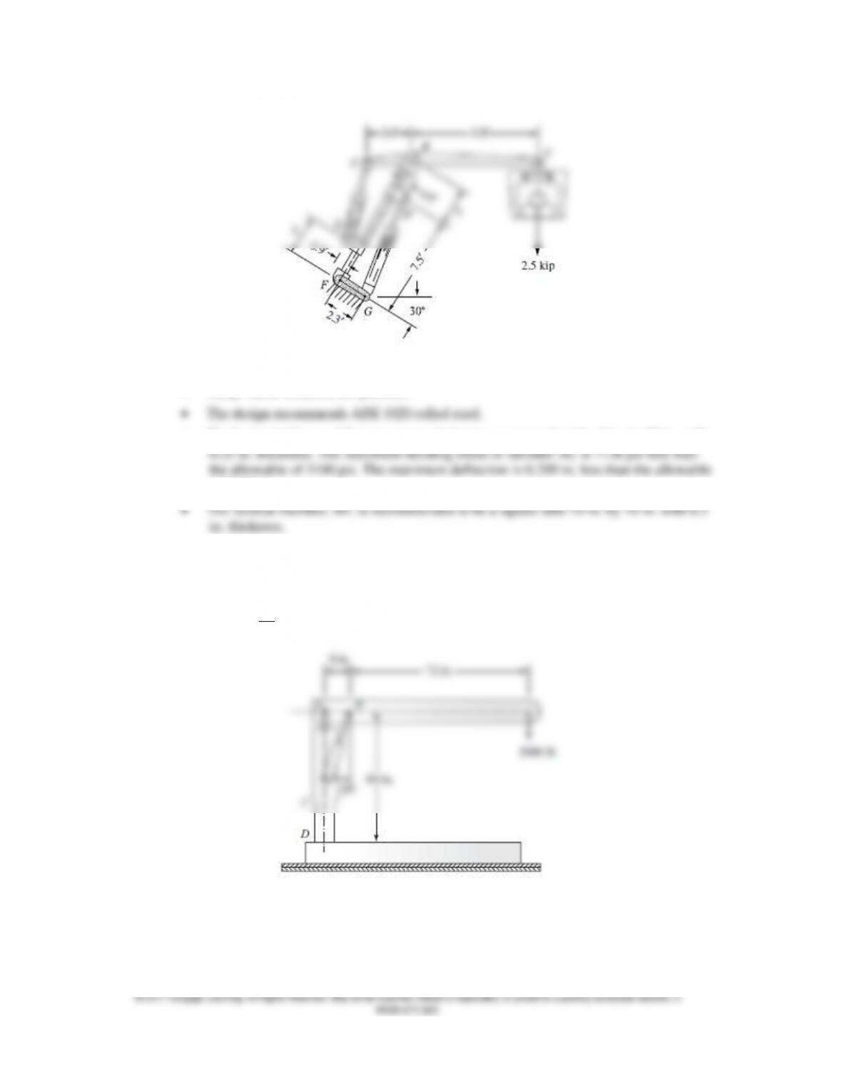
308
Figure P5–63
Many viable solutions are possible.
The horizontal beam, AC, is recommended to be a rectangular tube 4 in. by 16 in. with
of 0.300 in.
5.65 A small hydraulic floor crane as shown in Figure P5-65 carries a 5000 lb load. Determine the
size of the beam and column needed. Select either a standard box section or a wide-flange
section. Assume a rigid connection between the beam and column. The column is rigidly
connected to the floor. The allowable bending stress in the beam is 0.60Sy. The allowable
deflection is
1
360
of the beam length. Check the column for buckling.
Figure P5-65
Many viable solutions are possible.
The design recommends A36 structural steel.
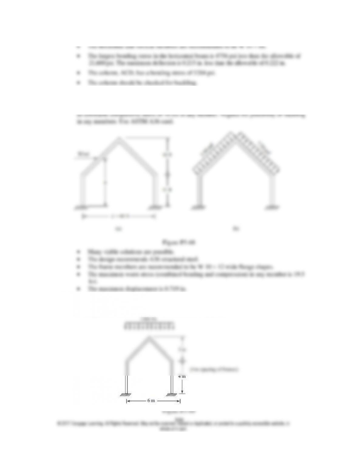
The horizontal and vertical members are recommended to be W 10 68.
The largest bending stress in the horizontal beam is 4756 psi less than the allowable of
21,600 psi. The maximum deflection is 0.215 in. less than the allowable of 0.222 in.
The column, ACD, has a bending stress of 5284 psi.
The column should be checked for buckling.
5.68 Design the gabled frame subjected to the external wind load shown (comparable to an
80 mph wind speed) for an industrial building. Assume this is one of a typical frame spaced
every 20 feet. Select a wide flange section based on allowable bending stress of 20 ksi and
5.69 Design the gabled frame shown for a balanced snow load shown (typical of the Mid-west)
for an apartment building. Select a wide flange section for the frame. Assume the allowable
bending stress not to exceed 140 MPa. Use ASTM A36 steel.
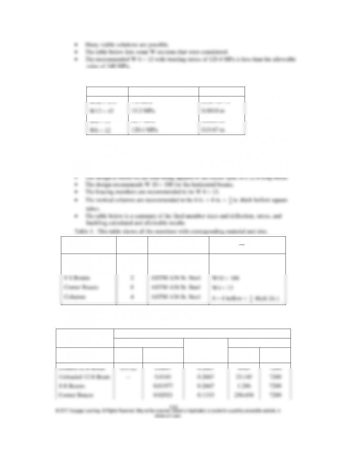
Many viable solutions are possible.
The table below lists some W sections that were considered.
The recommended W 6 12 with bending stress of 120.4 MPa is less than the allowable
value of 140 MPa.
The maximum displacement is 0.0147 m.
Table 1: Beam Trial Runs
Beam Section
Bending Stress (Local 3)
Displacement
W30 173
1.6 MPa
6.26*10^–5
W12 45
15.2 MPa
0.0010 m
W8 13
88.7 MPa
0.0082 m
W6 12
120.4 MPa
0.0147 m
5.70 Design a gantry crane that must be able to lift 10 tons as it must lift compressors, motors,
heat exchangers, and controls. This load should be placed at the center of one of the main
12-foot-long beams as shown in Figure P5-70 by the hoisting device location. Note that this
beam is on one side of the crane. Assume you are using ASTM A36 structural steel.
Many viable solutions are possible.
1
4
Member
Quantity
Material
Size (in.
lb
ft
)
loaded 12 ft beam
1
ASTM A36 St. Steel
W10 100
unloaded 12 ft beam
1
ASTM A36 St. Steel
W10 100
8 ft Beams
2
ASTM A36 St. Steel
W10 100
Corner Braces
8
ASTM A36 St. Steel
W4 13
Columns
4
ASTM A36 St. Steel
4 4 hollow
1
4
thick (in.)
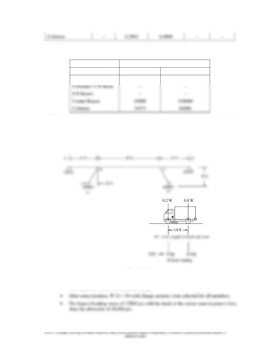
Table 2: This table shows that the maximum deflections are less than the allowable deflection, and
that the calculated bending stresses are less than the allowable stresses in the beams.
Calculations
Maximum Deflection (in.)
Allowable
Deflection (in.)
Bending Stress (psi)
Member
By Hand
Using
Autodesk
Calculated
Allowable
Loaded 12 ft Beam
0.0722
0.0847
0.2667
6405
7200
Unloaded 12 ft Beam
–
0.0141
0.2667
23.145
7200
8 ft Beams
–
0.01977
0.2667
1.286
7200
Corner Braces
–
0.02921
0.1333
256.654
7200
311
Columns
–
0.2863
0.4000
–
–
Table 3: This table shows that the corner braces and the columns have loads smaller than the load that
would cause buckling.
Buckling Strength (lb)
Member
Calculated load
Allowable load
Loaded 12 ft Beam
–
–
Unloaded 12 ft Beam
–
–
8 ft Beams
–
–
Corner Braces
24000
330000
Columns
24572
60000
5.71 Design the rigid highway bridge frame structure shown in Figure P5-71 for a moving truck
load (shown below) simulating a truck moving across the bridge. Use the load shown and
place it along the top girder at various locations. Use the allowable stresses in bending and
compression and allowable deflection given in the Standard Specification for Highway
Bridges, American Association of State Highway and Transportation Officials (AASHTO),
Washington, D.C. or use some other reasonable values.
Figure P5-71
Many viable solutions are possible.
A36 structural steel is chosen in the design.
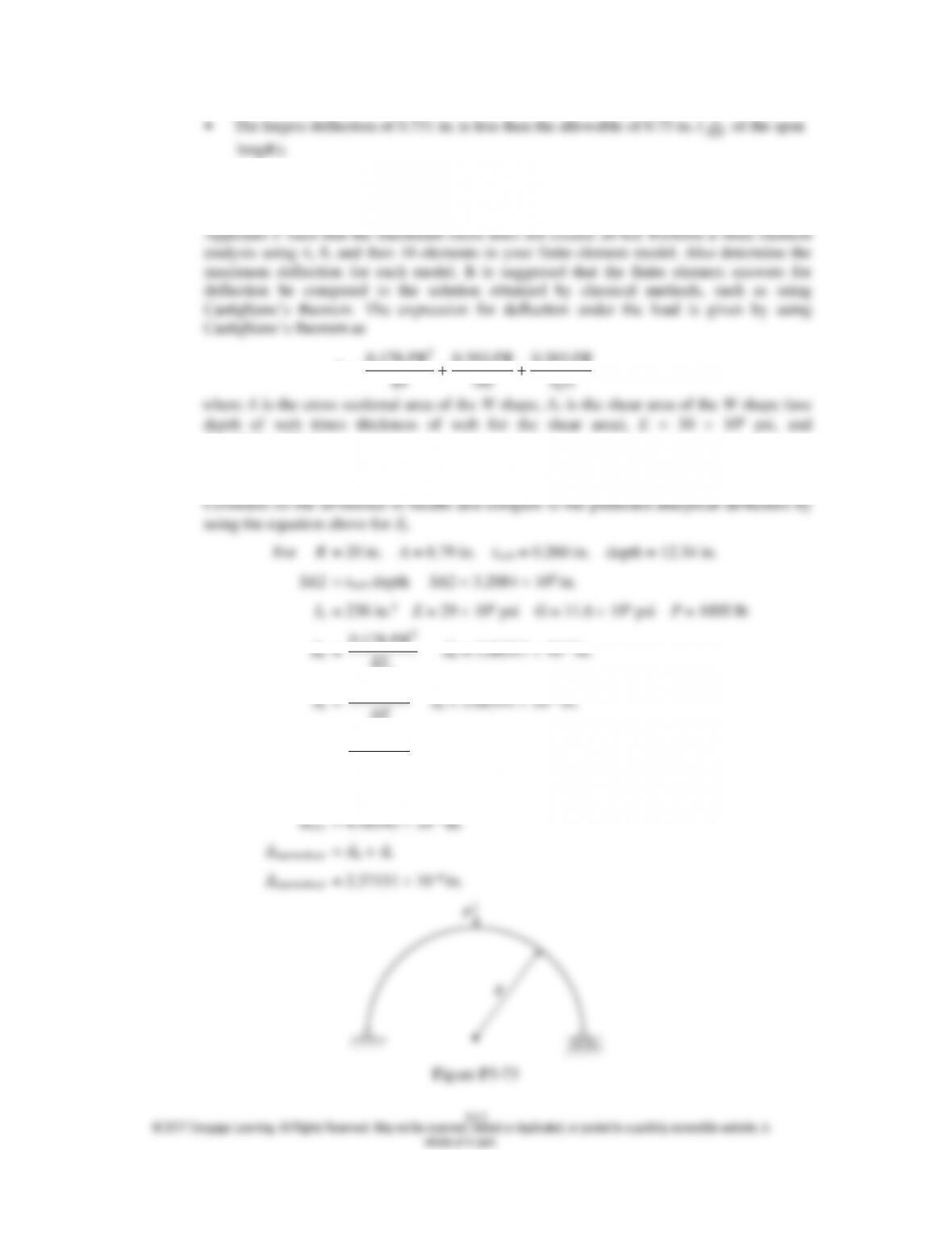
The largest deflection of 0.731 in. is less than the allowable of 0.75 in. (
1
800
of the span
length).
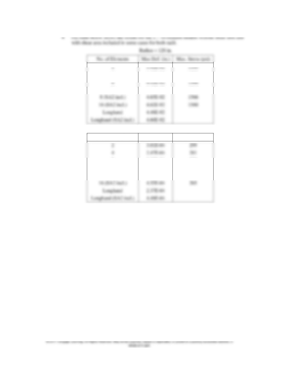
5.73 The curved semi-circular frame shown in Figure P 5-73 is supported by a pin on the left end
and a roller on the right end and is subjected to a load P = 1000 lb at its apex. The frame has
a radius to centerline of cross section of R = 120 in. Select a structural steel W shape from
y =
3
0.178 0.393 0.393
v
PR PR PR
EI AE A G
G = 11.5 106 psi.
Now change the radius of the frame to 20 in. and repeat the problem. Run the finite element
model with the shear area included in your computer program input and then without.
313
No. of Elements
Max Def. (in.)
Max. Stress (psi)
2
5.92E-02
1595
4
4.69E-02
1576
8
4.52E-02
1566
16
4.48E-02
1560
8 (SA2 incl.)
4.65E-02
1566
16 (SA2 incl.)
4.62E-02
1560
Longhand
4.48E-02
Longhand (SA2 incl.)
4.60E-02
Radius = 20 in.
No. of Elements
Max Def. (in.)
Max. Stress (psi)
2
3.01E-04
299
4
2.47E-04
281
8
2.39E-04
270
16
2.39E-04
265
8 (SA2 incl.)
4.55E-04
270
16 (SA2 incl.)
4.55E-04
265
Longhand
2.37E-04
Longhand (SA2 incl.)
4.48E-04

314