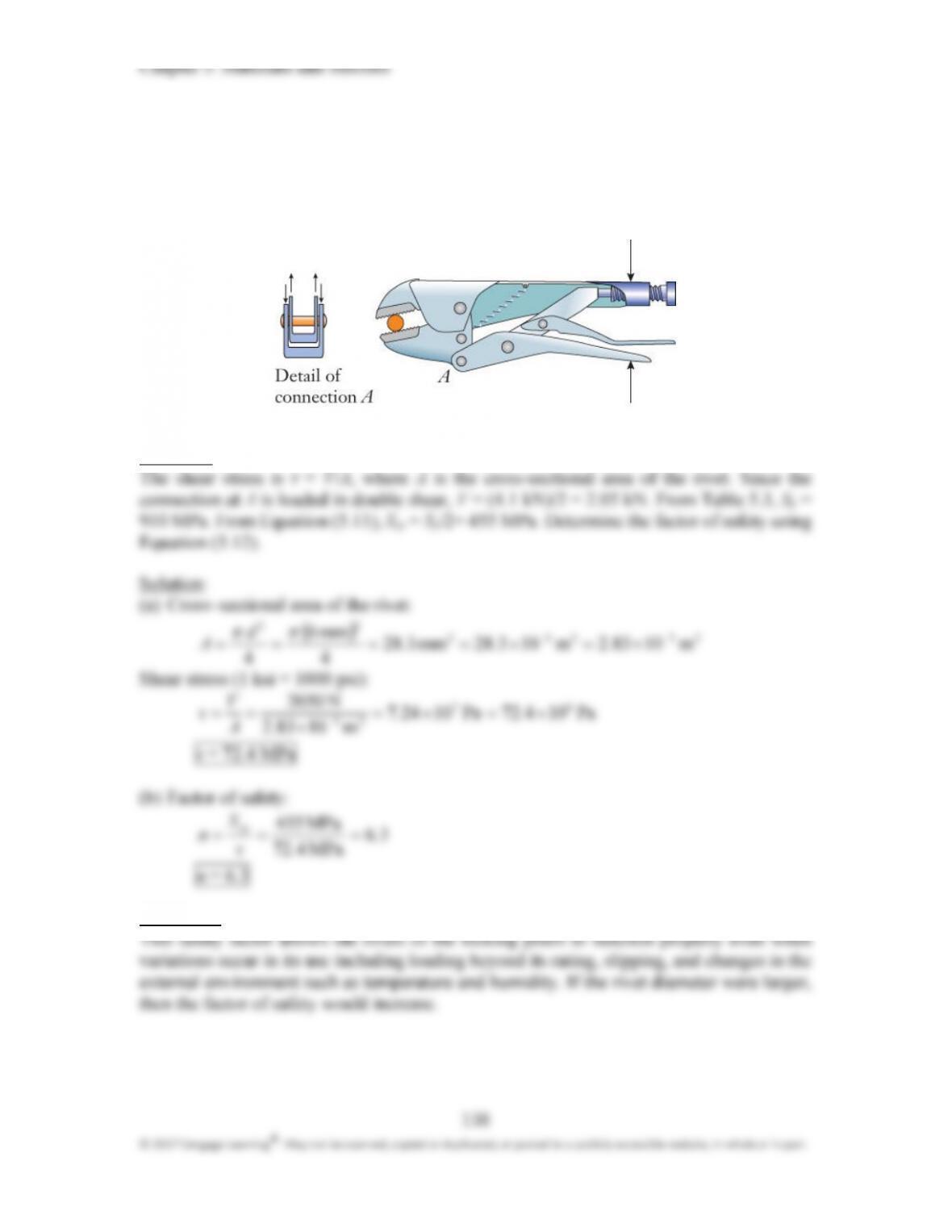
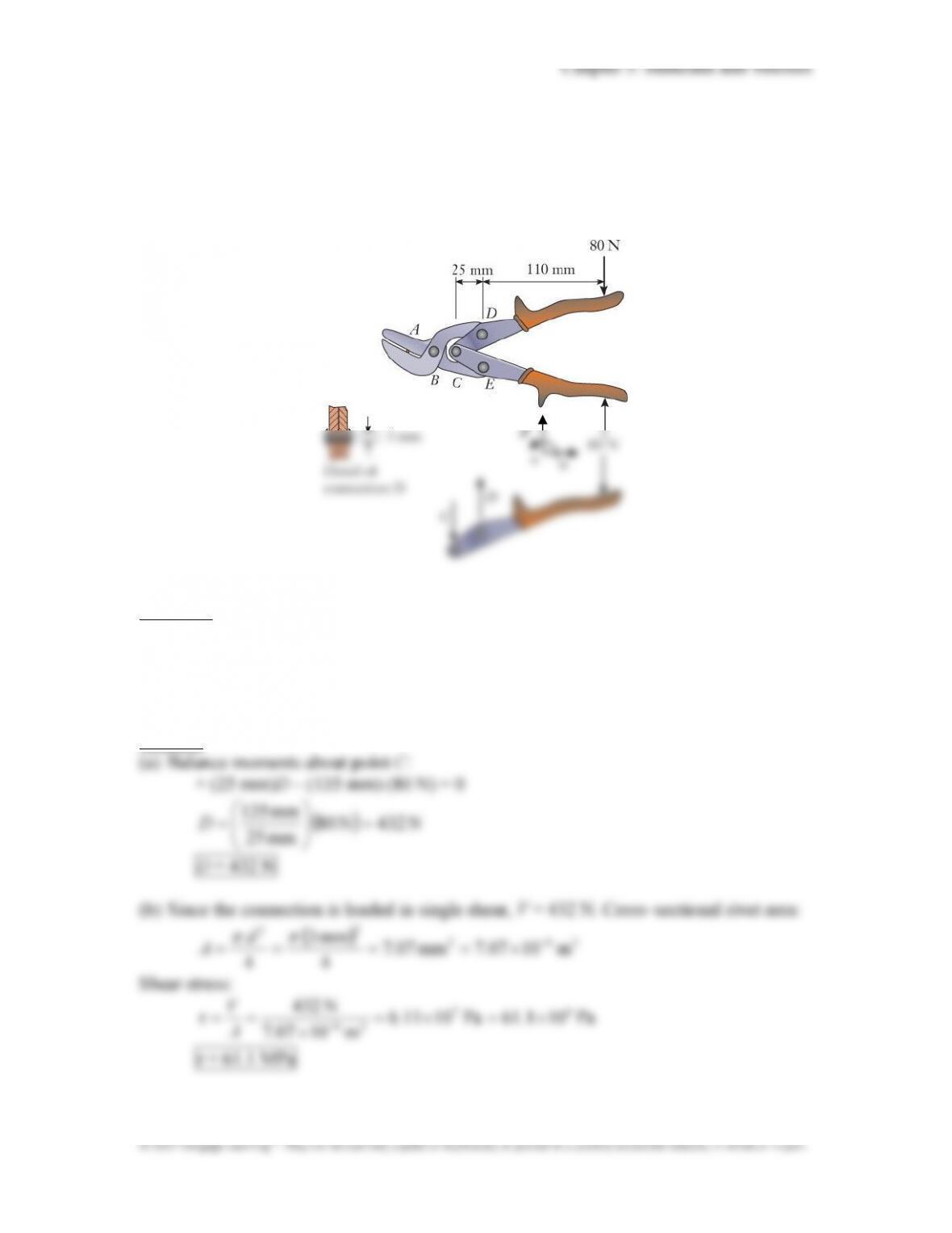
P5.31:
Compound lever shears cut through a piece of wire at A. (a) By using the free body
diagram of handle CD, determine the magnitude of the force at rivet D. (b) Referring to
the magnified cross9sectional drawing of the connection at D, determine the shear
stress in the rivet. (c) If the rivet is formed from 4340 steel alloy, what is the factor of
safety?
Approach:
Determine the force at connection D by summing moments about point C. The shear stress
is τ = V/A, where A is the cross–sectional area of the rivet and the connection is placed in
single shear. From Table 5.3, S
y
= 910 MPa. From Equation (5.11), S
sy
= S
y
/2= 455 MPa.
Determine the factor of safety using Equation (5.12).
Solution:
Chapter 5: Materials and Stresses
140
© 2017 Cengage Learning
®
. May not be scanned, copied or duplicated, or posted to a publicly accessible website, in whole or in part.
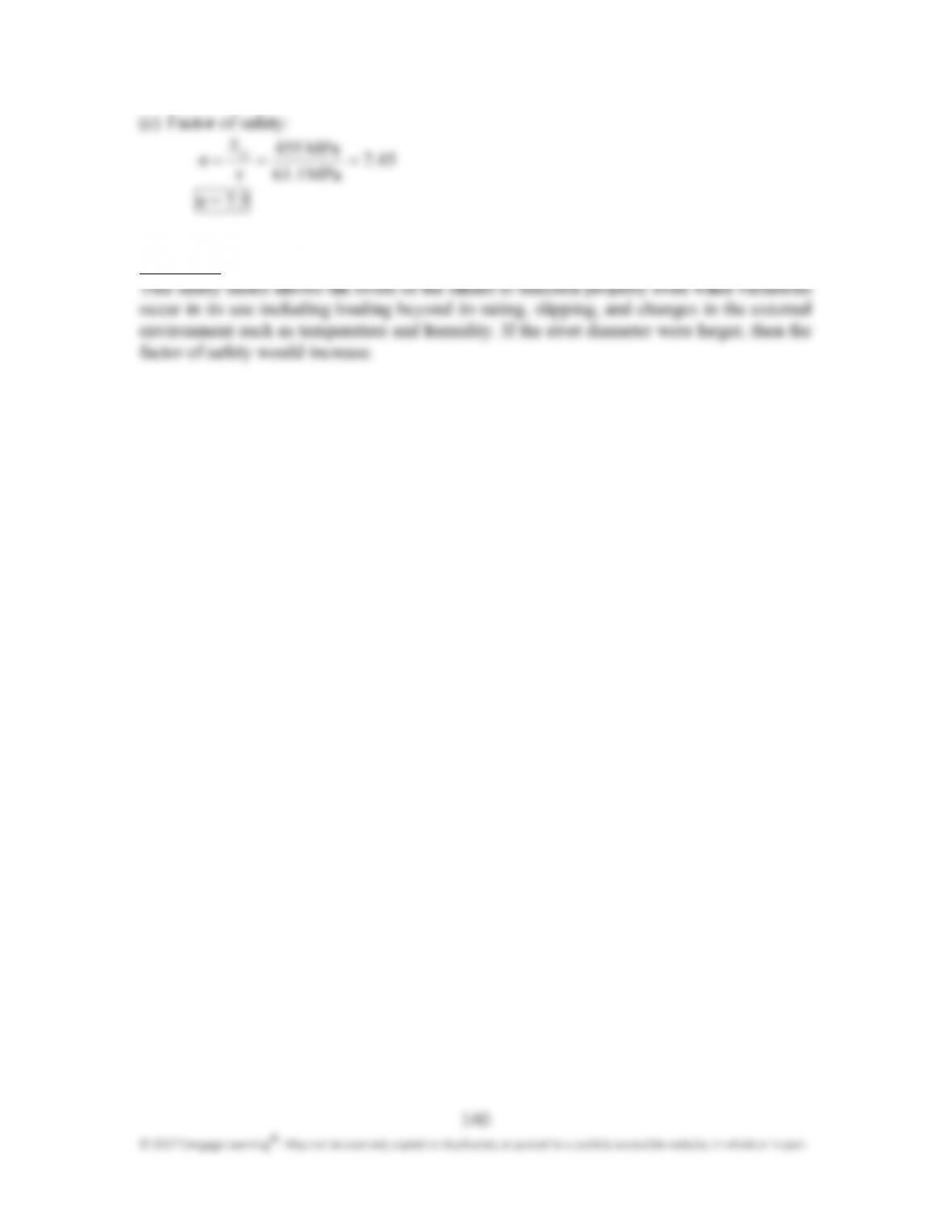
(c) Factor of safety:
457
MPa161
MPa455 .
.τ
S
n
sy
===
n = 7.5
Discussion:
141
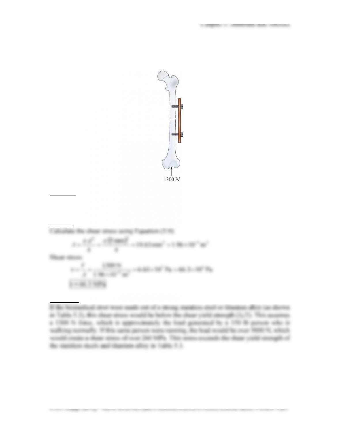
P5.32:
Plates and rods are frequently used to help rehabilitate broken bones. Calculate the
shear stress in the lower 5 mm diameter biomedical bolt if it is supporting a 1300 N
force from the bone.
Approach:
Calculate the shear stress in the rivet using Equation (5.9) τ = V/A, where A is the
cross–sectional area of the rivet and the connection is placed in single shear.
Solution:
Discussion:
142
P5.33*:
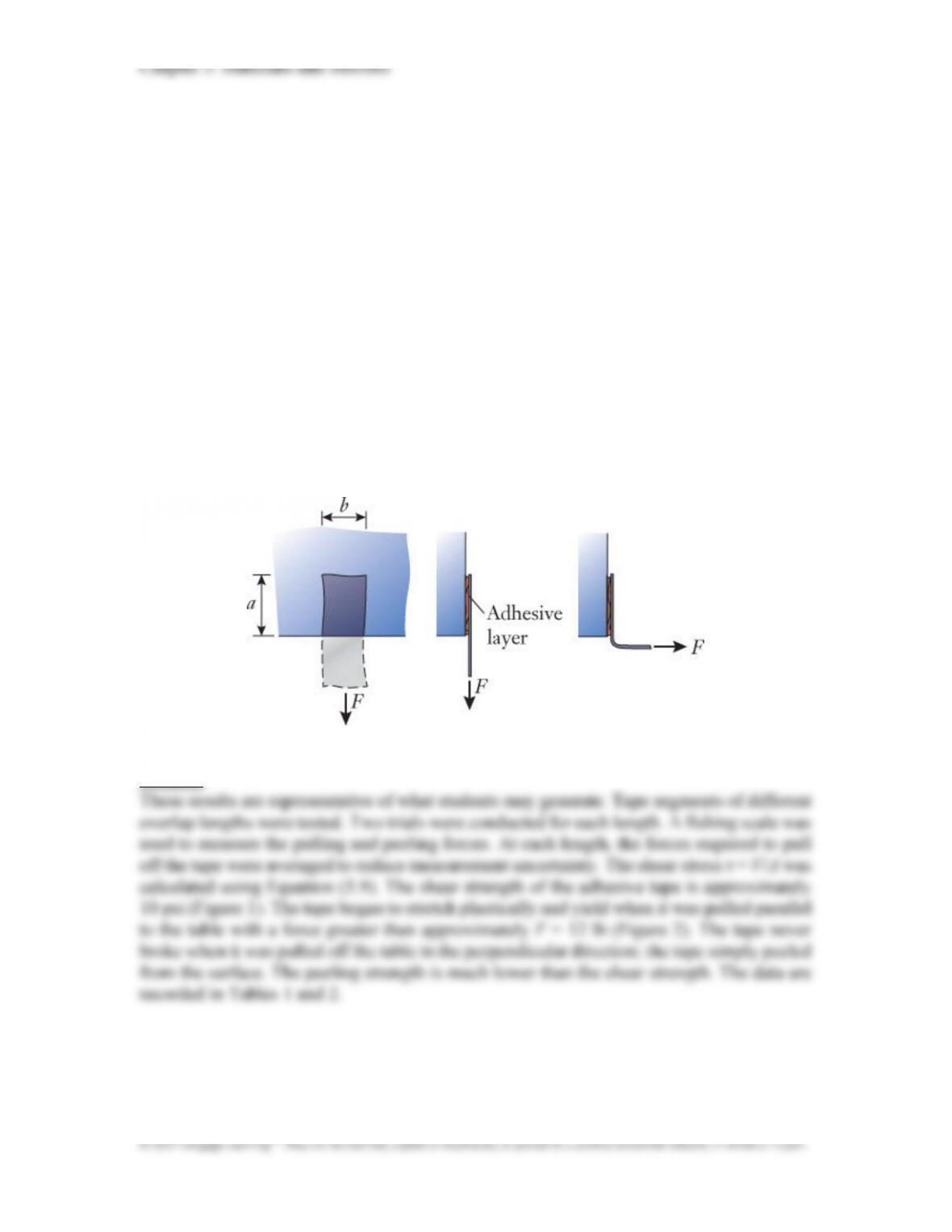
Adhesive tape is capable of supporting relatively large shear stress, but it is not
able to support significant tensile stress. In this problem, your group will measure the
shear strength of a piece of tape. (a) Cut about a dozen segments of tape having
identical length L and width b. The exact length isn’t important, but the segments
should be easily handled. (b) Develop a means to apply and measure the pull force F on
the tape. Use, for instance, dead weights (cans of soda or exercise weights) or a small
fishing scale. (c) Attach a segment of tape to the edge of a table, with only a portion of
tape adhering to the surface. In your tests, consider attachment lengths ranging between
a fraction of an inch and several inches. (d) Being careful to apply the pull force straight
along the tape, measure the value F necessary to cause the adhesive layer to slide or
shear off the table. Tabulate pull9force data for a half dozen different lengths a. (e)
Make graphs of pull force and shear stress versus a. From the data, estimate the value
of the shear stress above which the tape will slide and come loose from the table. (f) At
what length a did the tape break before it sheared off the table? (g) Repeat the tests for
the orientation in which F is applied perpendicular to the surface, tending to peel the
tape instead of shearing it. Compare the tape‘s strengths for shear and peeling.
Solution:
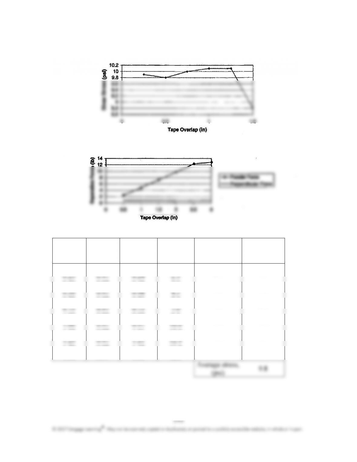
Chapter 5: Materials and Stresses
Figure 1: Shear stress for pulling forces in the parallel direction, as a function of tape
overlap length.
Figure 2: Comparison of pulling forces in the parallel and perpendicular directions
Table 1: Parallel force test
Length, a
Width, b Contact Shear Average shear Shear stress,
(in.) (in.) area, force, V force for two τ (psi)
A = ab (in
2
)
(lb) trials (lb)
0.25 0.97 0.24 2.5 2.4 9.9
0.50 0.97 0.48 5.0 4.8 9.8
0.75 0.97 0.73 7.5 7.3 10.0
1.00 0.97 0.97 9.5 9.8 10.1
1.25 0.97 1.21 12.0 12.3 10.1
1.50 0.97 1.45 13.0 12.8 8.8
1.50 0.97 1.45 12.5
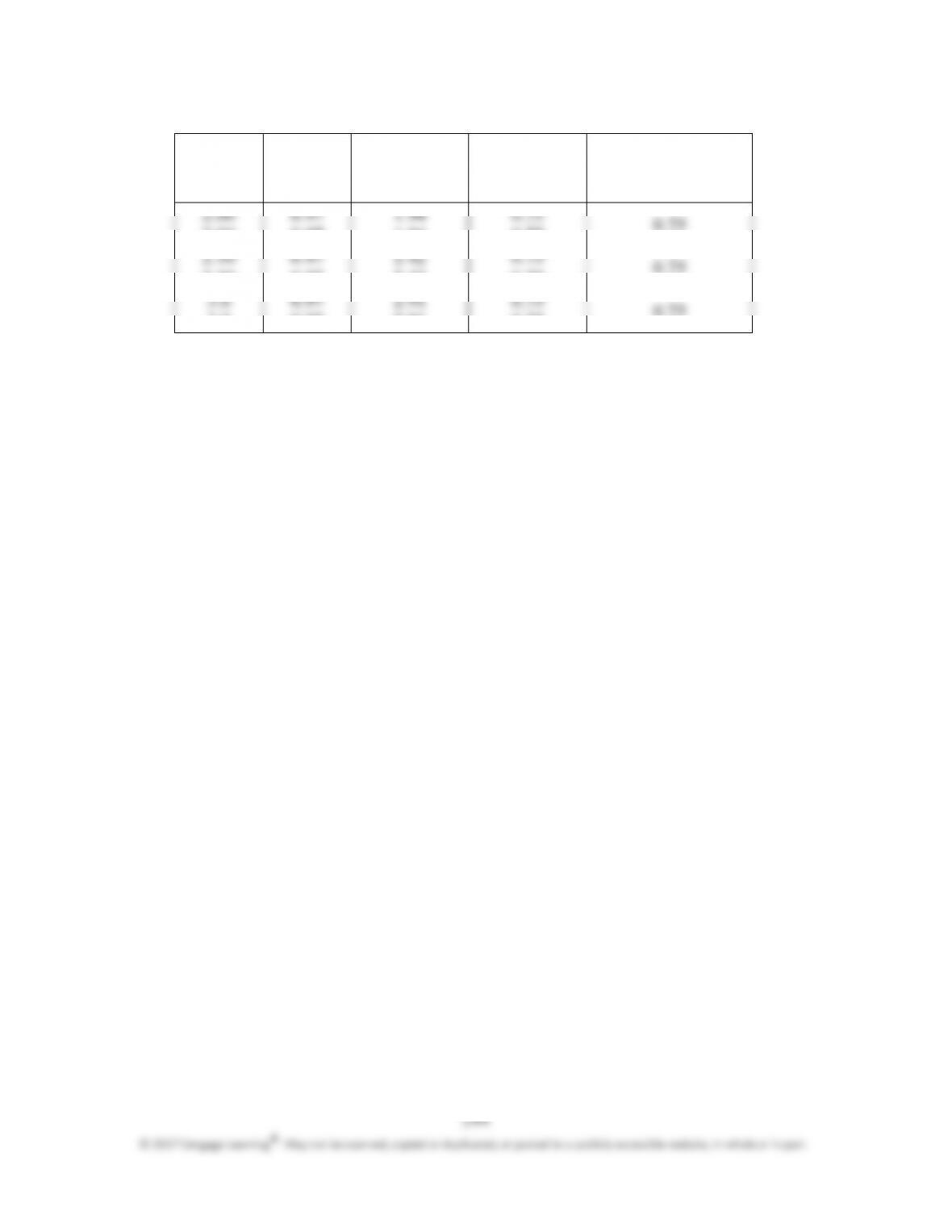
Chapter 5: Materials and Stresses
Table 2: Perpendicular force test
Length, a
Width, b Contact Peeling Average peeling
(in.) (in.) area, force, P force for two trials
A = ab (in
2
) (lb) (lb)
2.00 0.97 1.94 0.75
2.50 0.97 2.42 0.75
3.0 0.97 2.91 0.75
145
P5.34*:
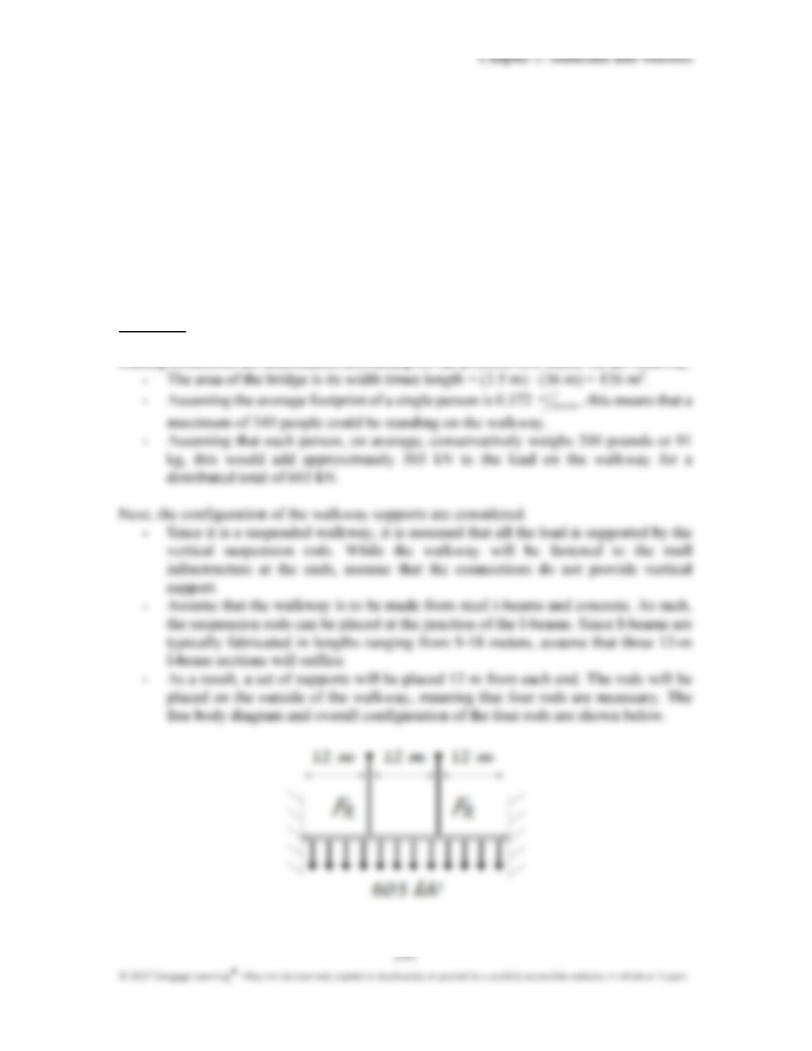
Using the bridge repair system in P5.15, as a group develop three additional
two9dimensional configurations that utilize different suspension arrangements. The
following design requirements must be met: Two9level access to the bridge must be
provided with the top platform at 90 in. below the road and the lower level 185 in.
below the road; each level must accommodate no more than two 200 lb workers;
standard structural steel cables (S
y
= 250 Mpa) of 0.50 in. diameter with varying
lengths are to be used. Evaluate the four designs (the three from this problem and the
one from P5.15) with respect to their factor of safety in worst9case loading conditions
and identify which configuration has the highest factor of safety.
Approach:
For each design configuration, perform the following steps:
9
Determine the worst case loading conditions. This may be a single condition, or a
series of worst case conditions for each cable (as in P5.16).
Solution:
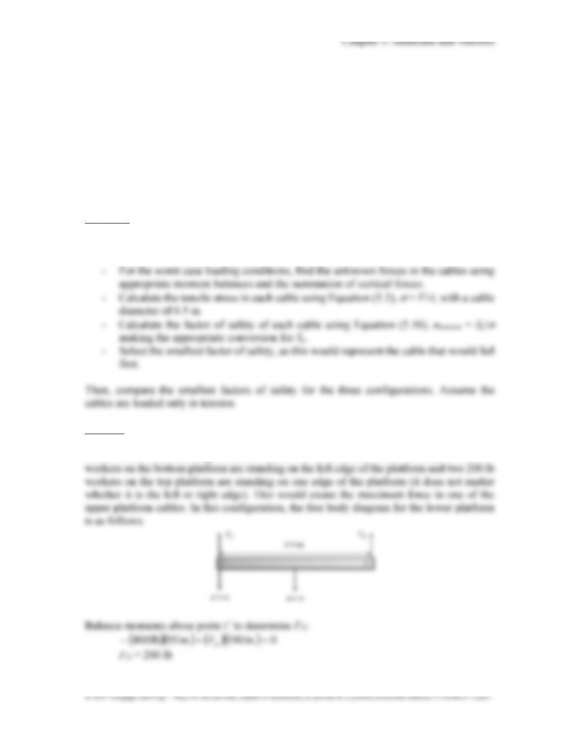
An example analysis is performed for the configuration in P5.15. The worst case condition
which would create the largest tensile force in one of the cables would be when two 200 lb
Chapter 5: Materials and Stresses
Sum forces in the vertical direction to find F
C
:
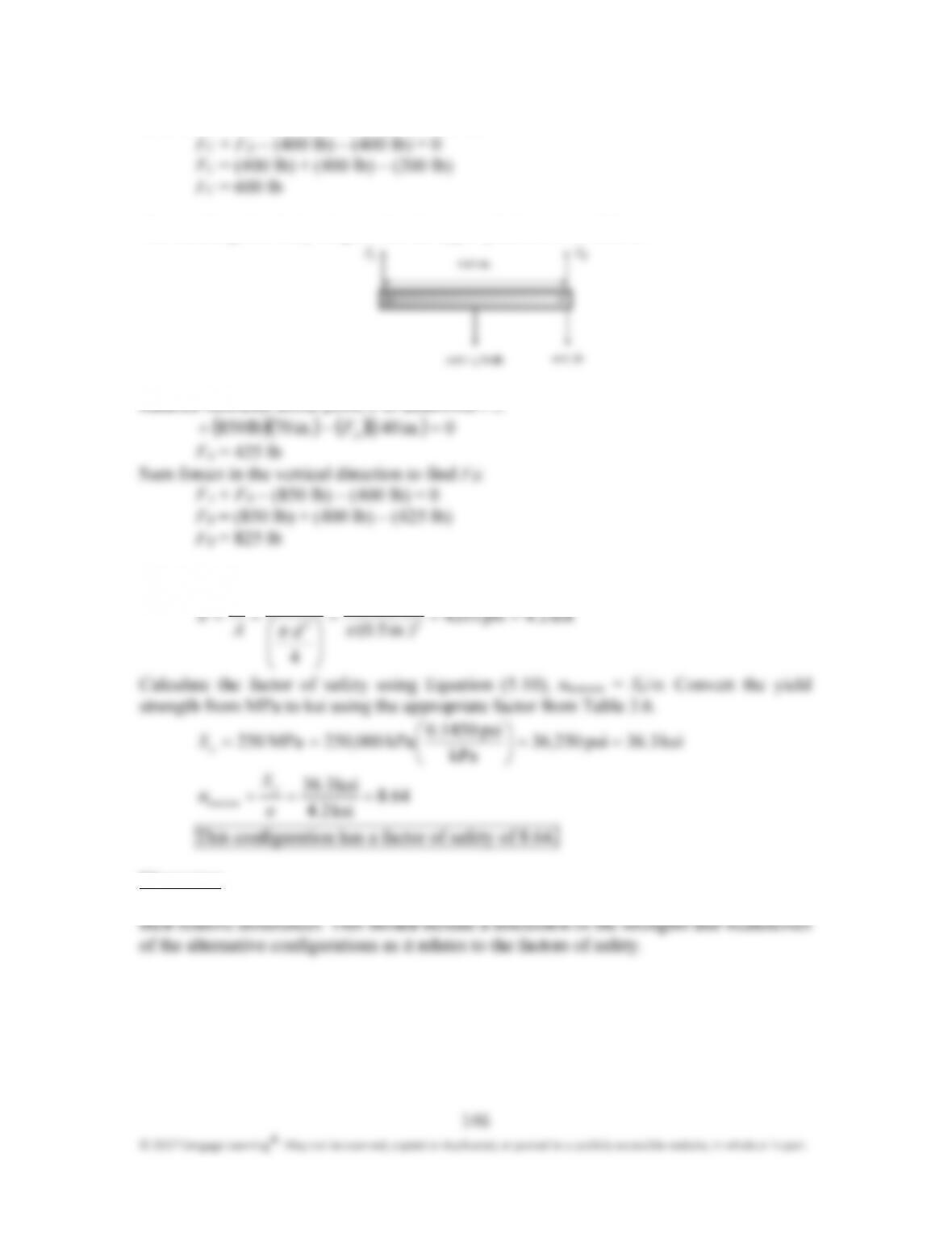
The resulting free body diagram for the upper platform is as follows:
(
)
(
)
(
)
(
)
0in140in70lb850
=
−
+
.F.
A
F
A
= 425 lb
Sum forces in the vertical direction to find F
B
:
F
A
+ F
B
– (850 lb) – (400 lb) = 0
F
B
= (850 lb) + (400 lb) – (425 lb)
F
B
= 825 lb
Using Equation (5.2), calculate the tensile stress:
lb8254
lb825
F
⋅
Discussion:
The discussion should focus on exploring and explaining the different factors of safety and
Chapter 5: Materials and Stresses
148
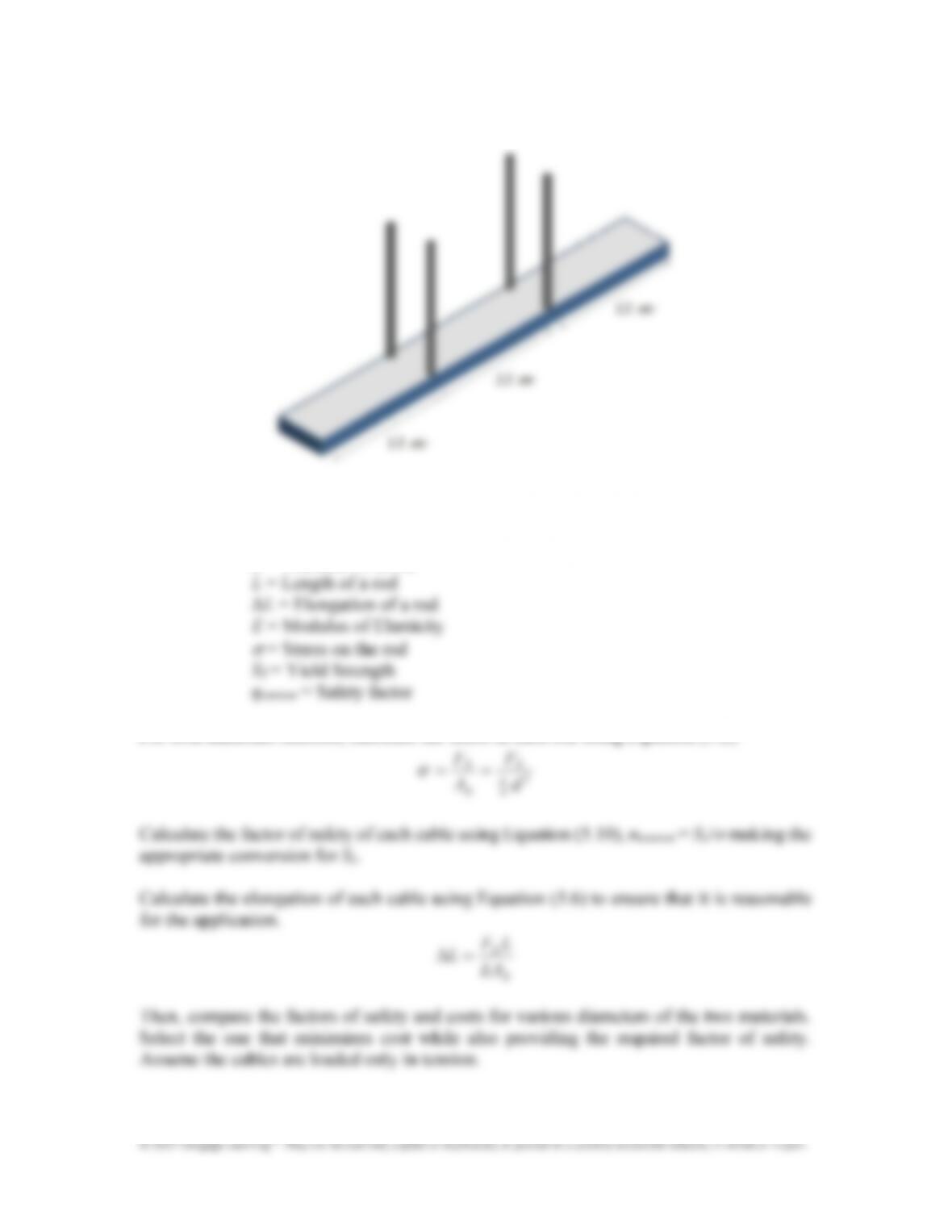
F
R
= Force on a single suspension rod
A
R
= Cross9sectional area of a rod (circular)
d = Diameter of a rod
For both materials selected, calculate the stress in each rod using Equation (5.2).
F
FR
R
σ
==
Chapter 5: Materials and Stresses
149
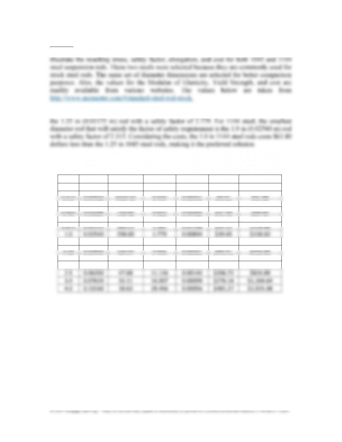
Solution:
Assuming the length of the rod is 6 m (as given in the problem), the following two tables
For 1045 steel, the smallest diameter rod that will satisfy the factor of safety requirement is
1045 Steel
(E = 200 GPa, S
Y
= 530 MPa)
(in)
(m)
σ
σσ
σ
(MPa)
“(m) $/rod Total $
0.25
0.00635
4768.04
0.111
0.14304
$4.40
$17.60
0.375
0.00953
2119.13
0.250
0.06357
$6.97
$27.88
0.5
0
0.01270
1192.01
0.445
0.03576
$10.97
$43.88
0.625
0.01588
762.89
0.695
0.02289
$17.00
$68.00
0.75
0.01905
529.78
1.000
0.01589
$23.69
$94.76
0.875
0.02223
389.23
1.362
0.01168
$32.22
$128.88
1
.0
0.02540
298.00
1.779
0.00894
$39.65
$158.60
1.25
0.03175
190.72
2.779
0.00572
$60.14
$240.56
1.5
0
0.03810
132.45
4.002
0.00397
$85.47
$341.88
1.75
0.04445
97.31
5.447
0.00292
$110.21
$440.84
2
.0
0.05080
74.50
7.114
0.00224
$136.78
$547.12
2.5
0.06350
47.68
11.116
0.00143
$206.72
$826.88
3
.0
0.07620
33.11
16.007
0.00099
$276.16
$1,104.64
4
.0
0.10160
18.63
28.456
0.00056
$481.27
$1,925.08
Chapter 5: Materials and Stresses
150
1144 Steel
(E = 200 GPa, S
Y
= 690 MPa)
(in) (m)
σ
σσ
σ
(MPa)
“(m) $/rod Total $
0.25
0.00635
4,768.04
0.145
0.14304
$4.30
$17.20
0.375
0.00953
2,119.13
0.326
0.06357
$9.12
$36.48
0.5
0
0.01270
1,192.01
0.579
0.03576
$14.44
$57.76
0.625
0.01588
762.89
0.904
0.02289
$20.75
$83.00
0.75
0.01905
529.78
1.302
0.01589
$27.79
$111.16
0.875
0.02223
389.23
1.773
0.01168
$35.37
$141.48
1
.0
0.02540
298.00
2.315
0.00894
$44.19
$176.76
1.25
0.03175
190.72
3.618
0.00572
$67.58
$270.32
1.5
0.03810
132.45
5.210
0.00397
$93.82
$375.28
1.75
0.04445
97.31
7.091
0.00292
$121.98
$487.92
2
.0
0.05080
74.50
9.262
0.00224
$153.25
$613.00
2.5
0.06350
47.68
14.471
0.00143
$230.78
$923.12
3
.0
0.07620
33.11
20.839
0.00099
$416.05
$1,664.20
4
.0
0.10160
18.63
37.047
0.00056
$753.67
$3,014.68
Choose four 1144 Steel rods for a total cost of $176.76 and a safety factor of greater than 2.
The rods should be placed in sets of two on the outside of the walkway, one set 12 m from
one end of the walkway and the other set 12 m from the other end.
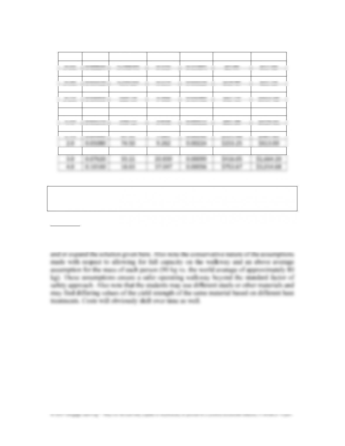
Discussion:
There is no one solution to this problem, as for many design problems. The conclusions
drawn should be evaluated on the assumptions made, and the arguments that support them.
Further consideration of connecting elements and other assembly components may change