360
L
=
10 m
360
= 0.0278 m
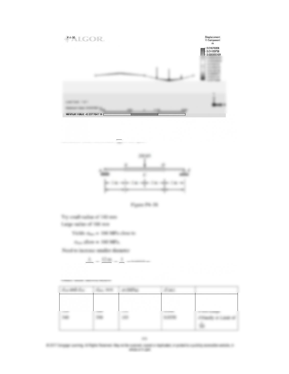
4.38 For the stepped shaft shown in Figure P4–38, determine a solid circular cross section for
each section shown such that the bending stress does not exceed 160 MPa and the maximum
deflection does not exceed
L
360
of the span.
360
L
=
12 m
360
=
1
30
= 0.0333 m
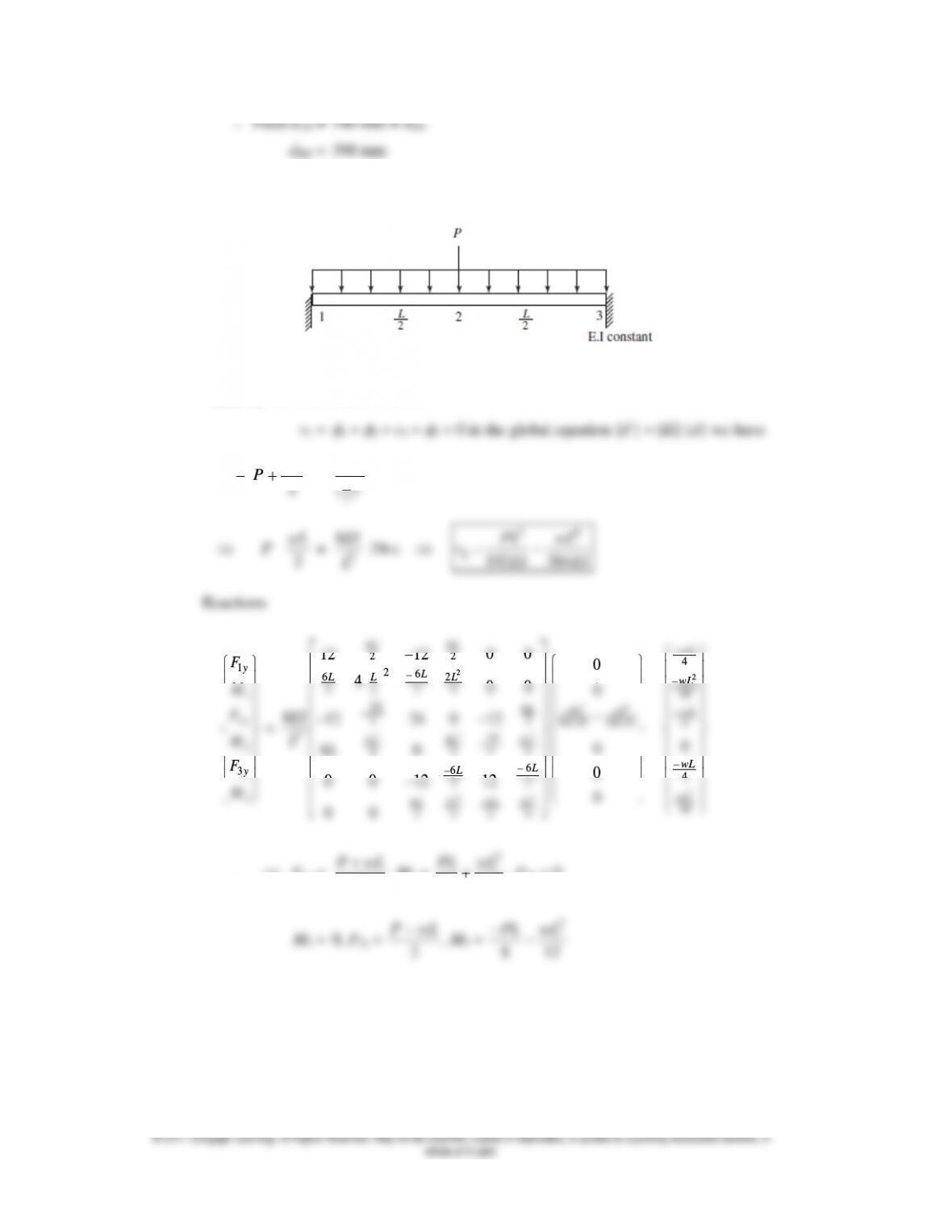
4.39
Applying the boundary conditions
2
wL
P
=
3
2
()
L
EI
[24v2]
wL
8EI
34
PL wL
2
3
3
y
M
F
M
2
22
22
36
8
22
4 4 2 4
6
6
22
66
24
2 2 2 4
0
60
0
0012 12
0
00
L
L
LL
L
L
LL
LL
LL
2
4
48
0
wL
wL
F1y =
2
P wL
, M1 =
2
8 12
PL wL
, F2y = 0
2
P wL
2
8 12
PL wL
4.40
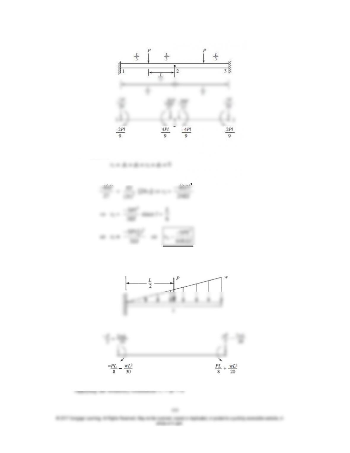
After applying the boundary conditions
We have in the equation {F} = [K] {d} the following
40
P
EI
3
40
Pl
3
EI
2
648
4.41
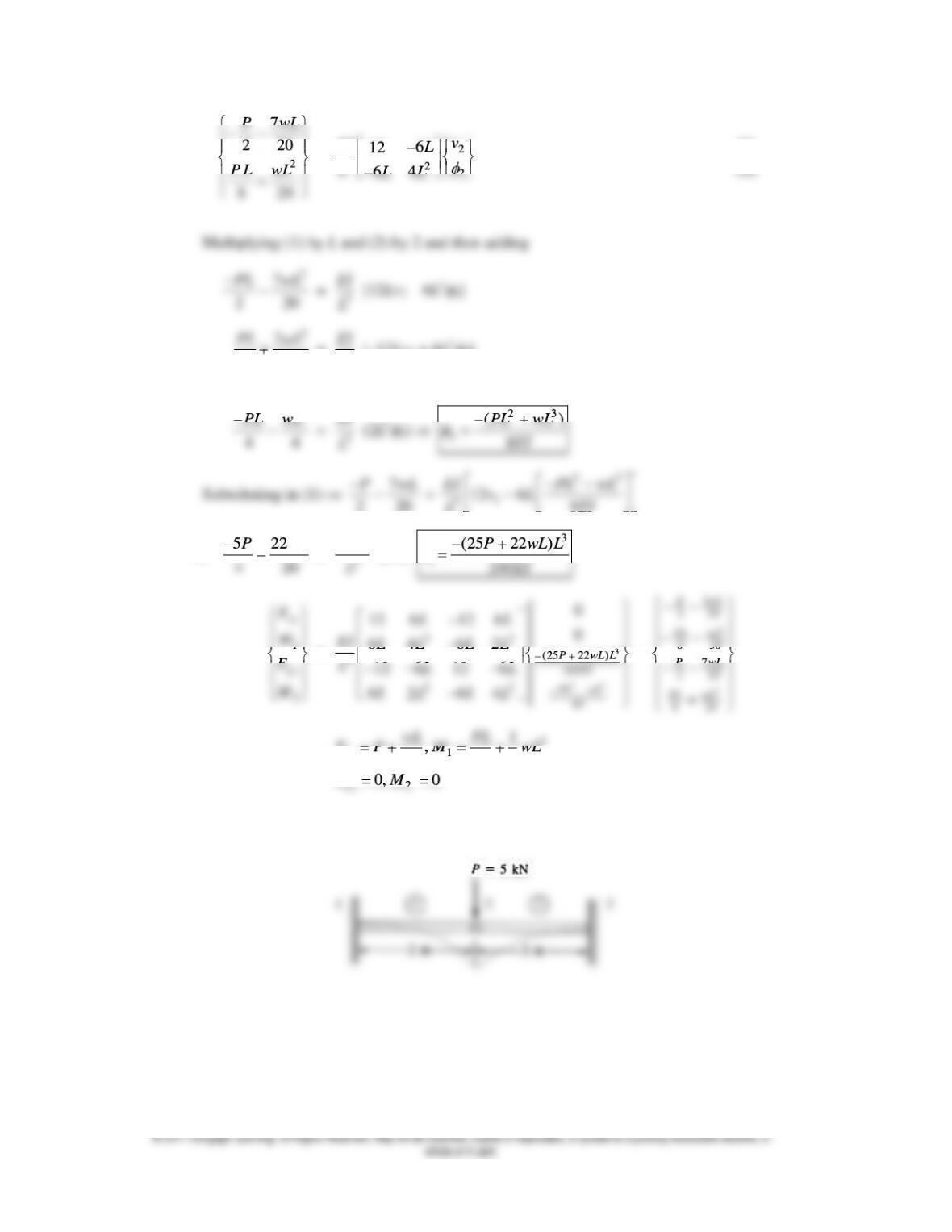
194
2
7
2 20
8 20
P wL
P L wL
=
2
322
(1)
6
12
(2)
64
v
EI L
LLL
2 20
3
L
2
2
4 20
PL wL
=
3
EI
L
[–12Lv2 + 8L2
2]
———————————————
2
44
PL wL
3
EI
L
23
()
8
PL wL
EI
7
2 20
P wL
23
2
312 6 8
EI PL wL
L
5 22
4 20
P wL
=
3
12EI
L
v2
3
2
(25 22 )
240
P wL L
vEI
1
1
2
2
y
y
F
M
F
M
=
3
23
22
(25 22 )
3240
22
–
0
66
12 12
0
66
42
66
12 12
66
24
P wL L
EI
PL wL
EI
LL
EI LL
LL
LLL
LL
LL
–
2
2
3
2 20
8 30
7
2 20
8 20
wL
P
wL
PL
wL
P
wL
PL
2
11
22
1
,
2 2 3
0, 0
y
y
wL PL
F P M wL
FM
4.42
Assume the hinge as a part of the first element. Therefore, stiffness matrix for element 1 is
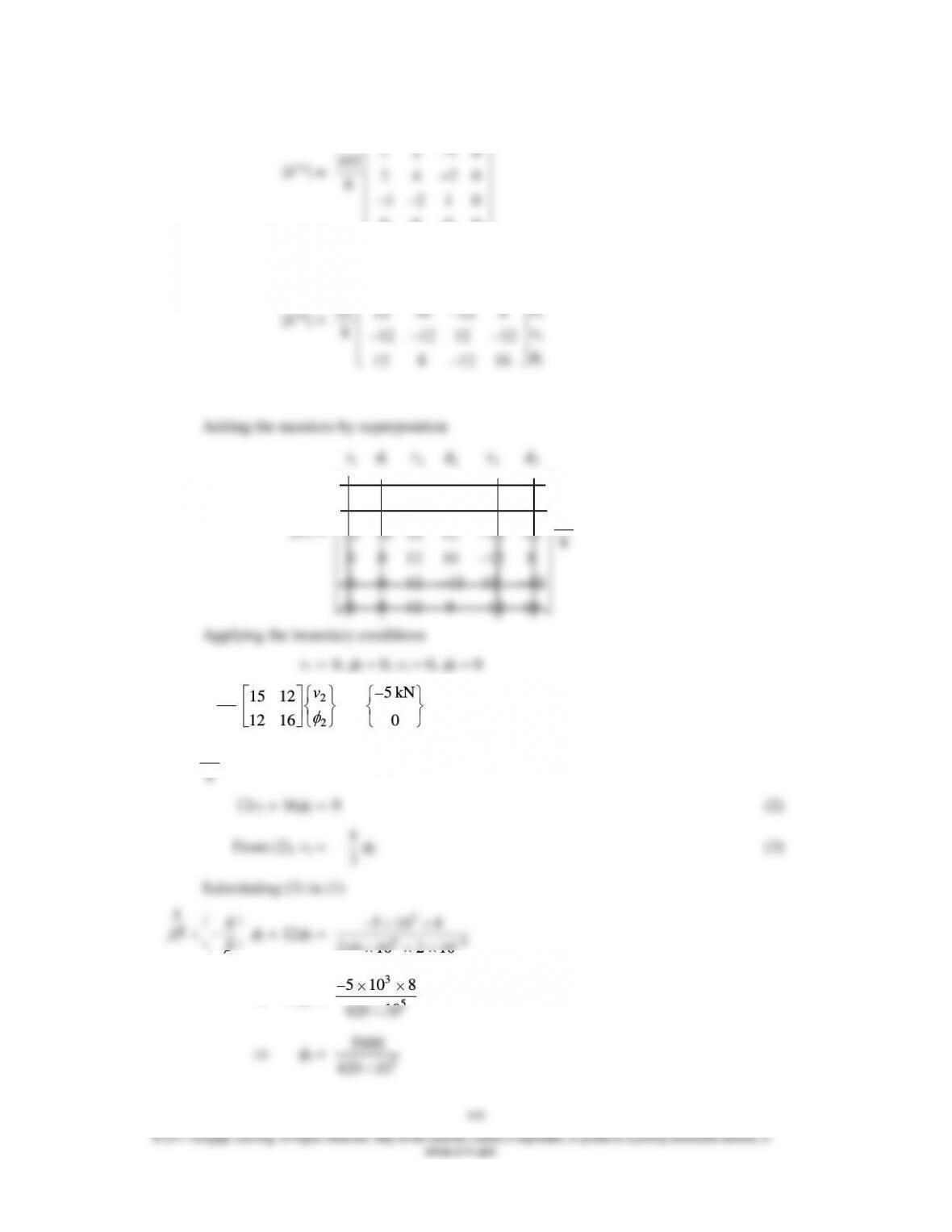
1 1 2 2
0
1 2 1
30
2 4 2
8
0
1 2 1
0 0 0 0
vv
EI
Stiffness matrix of element 2 is
2
2
3
3
12 12 12 12
16 8
12 12
812 12 12 12
8 16
12 12
v
EI
v
Adding the matrices by superposition
[K] =
33
1 1 2 2
3 6 3 0 0 0
6 6 0 0 0
12
3 6 15 12 12 12 8
0 0 16 8
12 12
00
12 12 12 12
0 0 8 16
12 12
v
vv
EI
8
EI
2
2
15 12
16
12
v
=
5 kN
0
8
EI
[15v2 + 12
2] = – 5000 N (1)
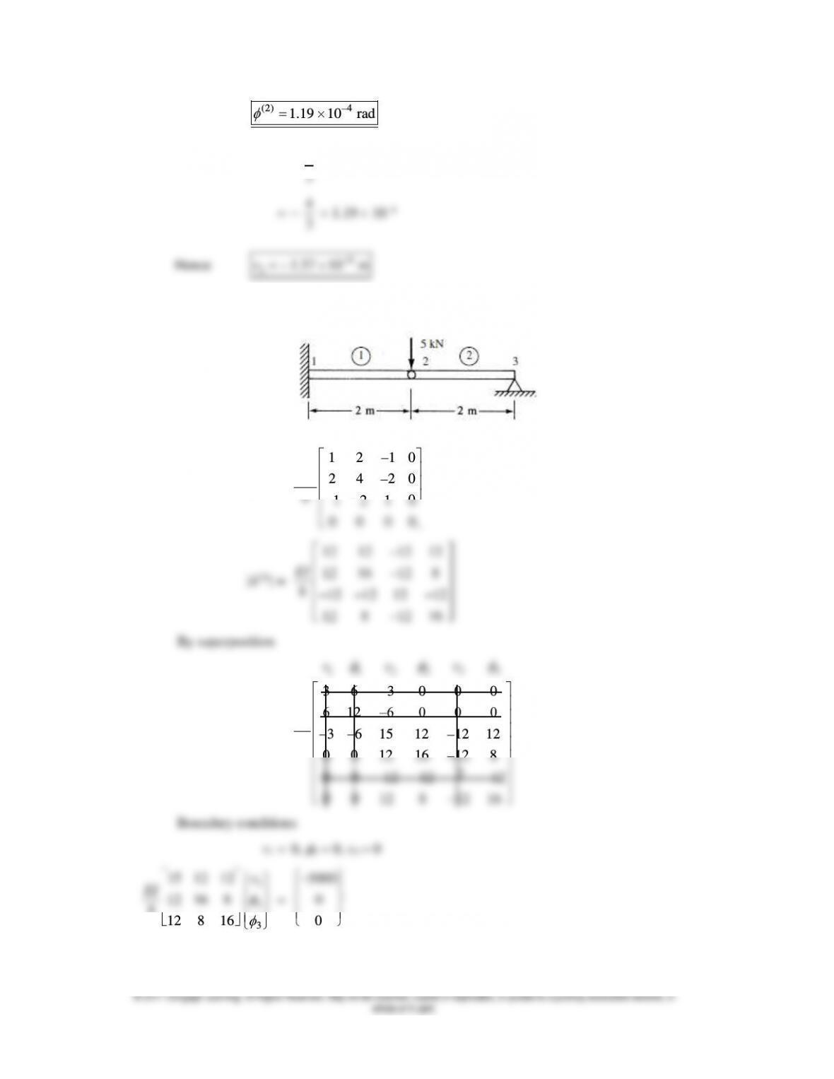
(2) 4
21.19 10 rad
v2 = –
4
3
2
4
3
Hence
4
21.57 10 mv
4.43
[k(1)] =
0
1 2 1
30
2 4 2
80
1 2 1
0 0 0 0
EI
12 12 12 12
16 8
12 12
EI
[K] =
33
1 1 2 2
3 6 3 0 0 0
6 –6 0 0 0
12
3 6 15 12 12 12
8
0 0 16 8
12 12
2
00 12 12 12
0 0 8 16
12 12
v
vv
EI
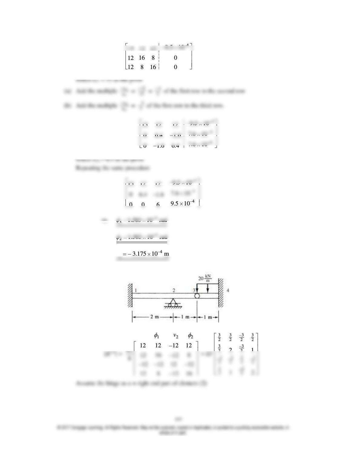
4
9.5 10
15 12 12
16 8 0
12
8 16 0
12
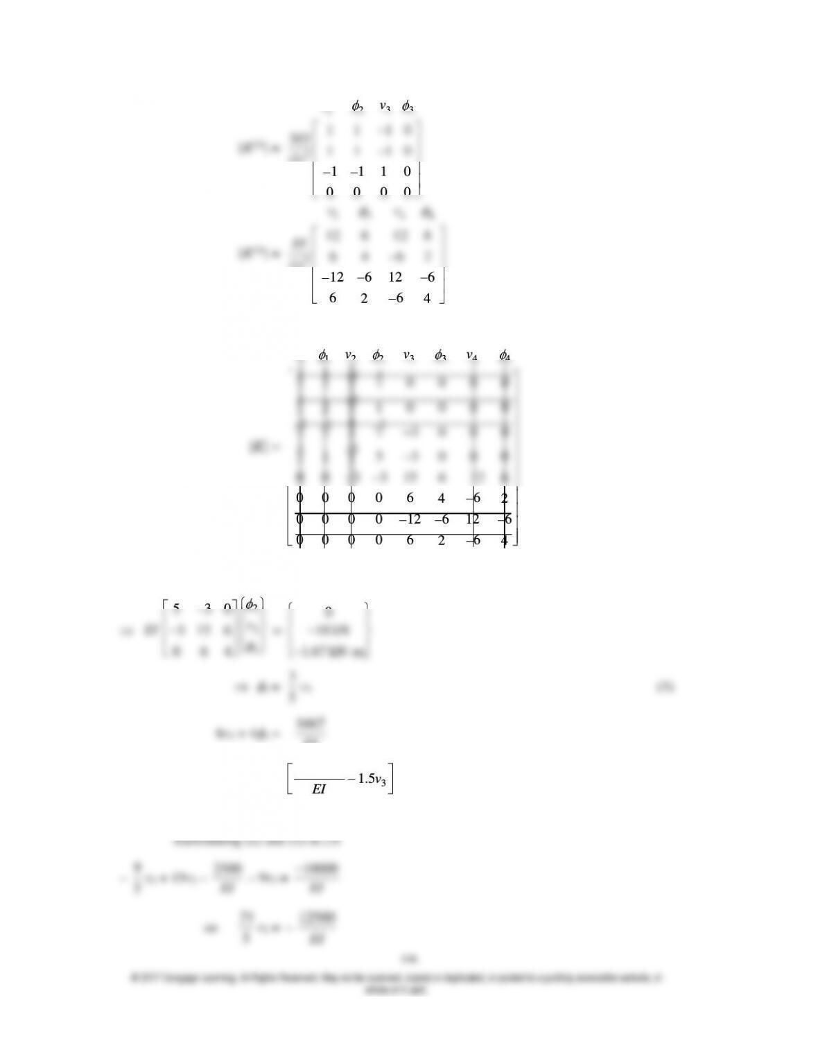
[K(2)] =
33
22
3
0
1 1 1
30
1 1 1
(1) 0
1 1 1
0 0 0 0
v
v
EI
[K(3)] =
3344
3
66
12 12
66
42
(1) 66
12 12
66
24
vv
EI
By superposition
33
1 1 2 2 4 4
3 3 3 3
2 2 2 2
33
22
3 3 9 3
2 2 2 2
0000
0000
21
3 0 0 0
v
v v v
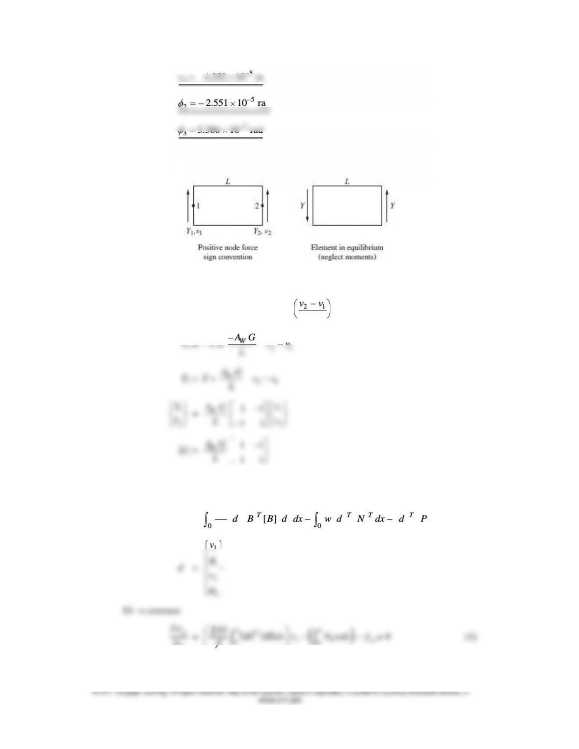
5
34.252 10 mv
5
22.551 10 rad
5
35.386 10 rad
4.46
Figure P4–46
Y = AW
= AW G
= Aw G
21
vv
L
vv
W
AG
L
21
Y2 = Y =
W
AG
L
21
vv
1
2
Y
Y
=
W
AG
L
1
2
11
11
v
v
[k] =
W
AG
L
11
11
4.47 From Equation (4.7.15)
p =
00
[]
2
LL
T
T T T
EI d B B d dx w d N dx d P
1
1
v
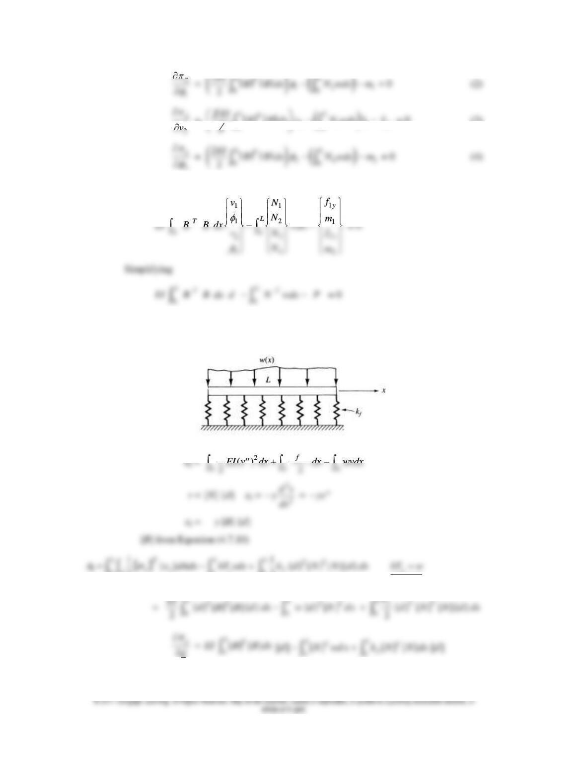
200
1
p
1 2 1
00
2
2
LL
T
EI B B dx N wdx m
2
p
v
=
2 3 1 2
00
21
2
LL
T
y
EI B B dx v N wdx f
= 0 (3)
2
p
2 4 2
00
2
2
LL
T
EI B B dx N wdx m
Equations (1) – (4) in matrix form are
11
12
00
3
2
24
LL
T
vN
N
v
N
1
1
2
2
y
y
f
m
f
m
Simplifying
EI
00
LL
T
T
B B dx d N wdx P
= 0
4.49
2
2
0 0 0
1()
22
L L L
f
kv
v = [N] {d}
x =
2
2
dv
ydx
=
yv
x = –
y
[B] {d}
[B] from Equation (4.7.10)
1{}
LL
T
1{ } [ ] [ ]{ }
LTT
d
0[ ] [ ]
00
f
6
[]k
= EI
00
[ ] [ ] [ ] [ ]
LL
TT
f
B B dx k N N dx
4.79 Find the deflection at the mid-span using four beam elements, making the shear area zero
and then making the shear area equal to
5
6
times the cross-sectional area (b times h). Then
make the beam have decreasing spans of 200 mm, 100 mm, and 50 mm with zero shear area
5