Chapter 4: Forces in Structures and Machines
92
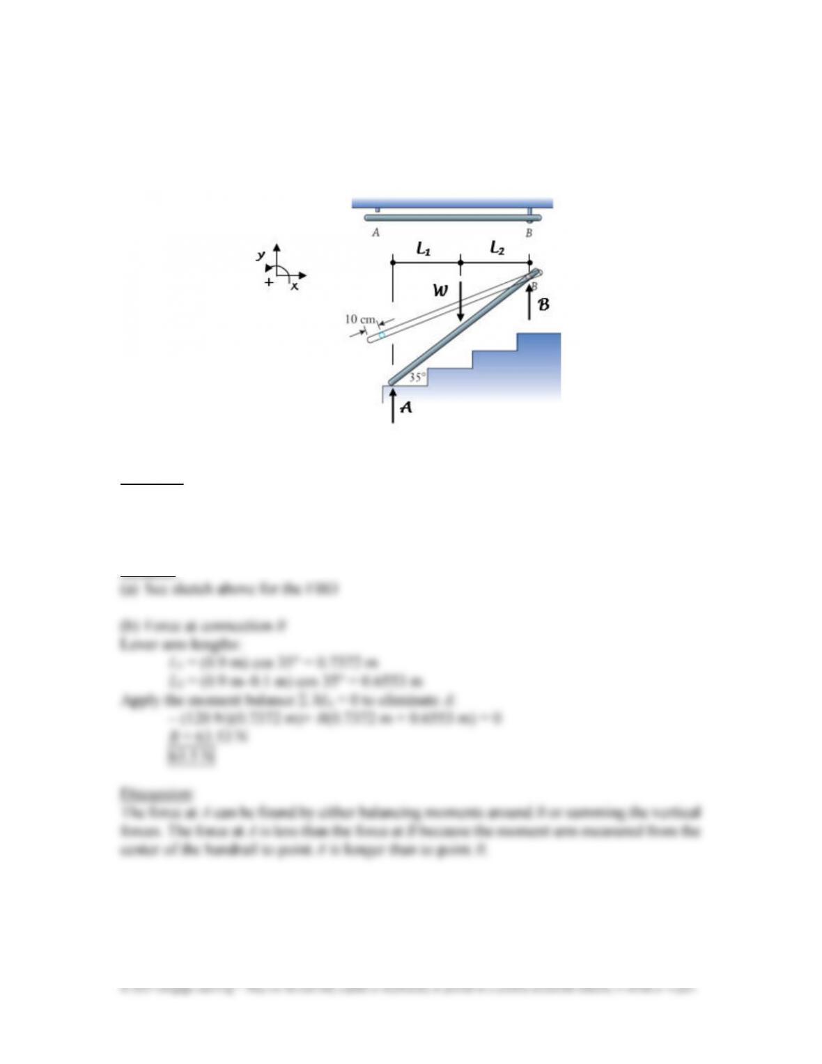
A handrail, which weighs 120 N and is 1.8 m long, was mounted to a wall adjacent
to a small set of steps. The support at A has broken, and the rail has fallen about the
loose bolt at B so that one end now rests on the smooth lower step. (a) Draw a free body
diagram of the handrail. (b) Determine the magnitude of the force at B.
Approach:
The contact force between the rail and step is unknown in magnitude, but it does act
vertical. Assuming the rail is in static equilibrium and by balancing moments about that
contact point, that unknown is eliminated and B can be found directly.
Solution:
Chapter 4: Forces in Structures and Machines
93
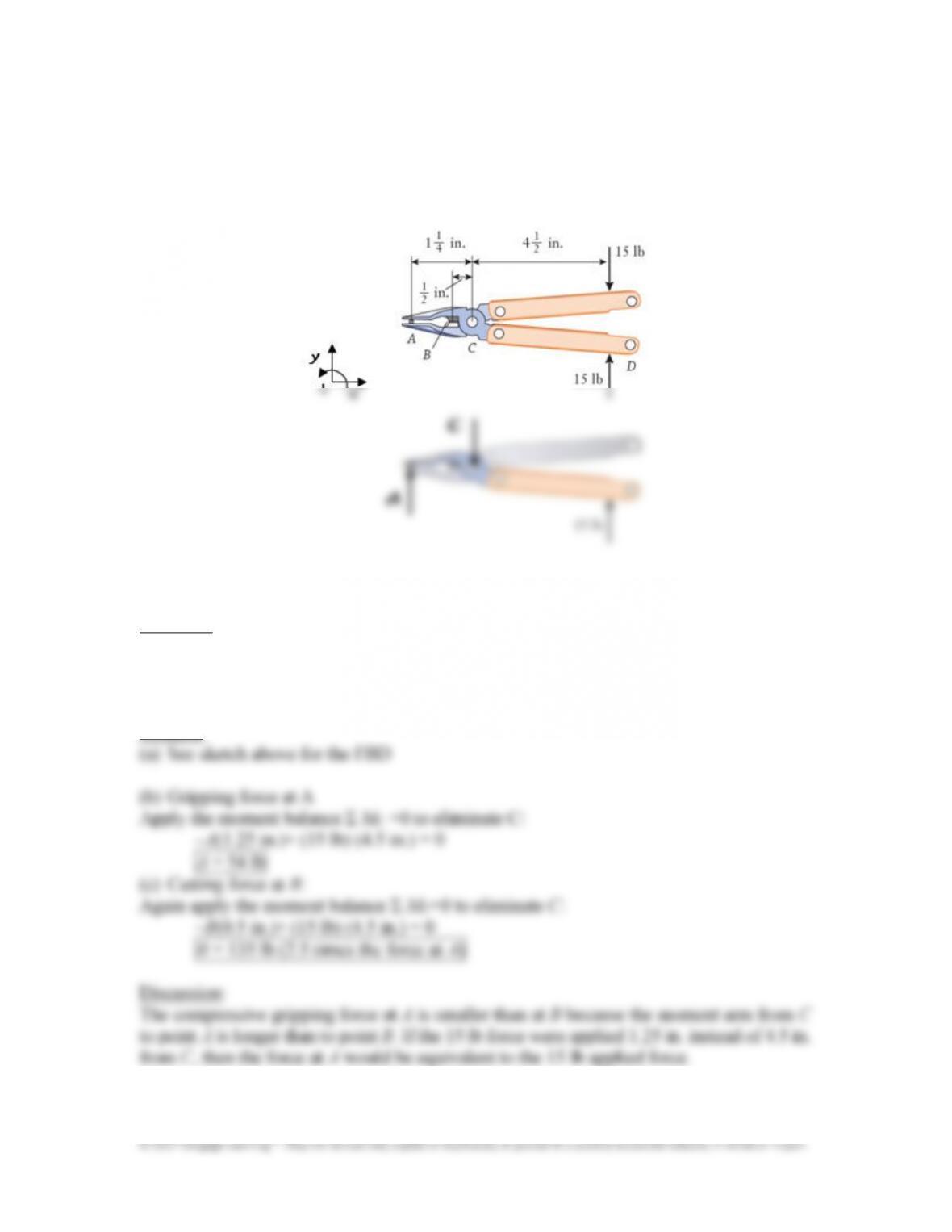
The multipurpose utility tool grips a cotter pin at A while 15 lb forces are applied to
the handles. (a) Complete the free body diagram of the combined upper jaw and lower
handle assembly, which has been only partially drawn. (b) Calculate the force acting at
A. (c) Alternatively, how much greater would the force be if the pin was being cut at B?
Approach:
The compressive gripping force at A is vertical, and force C acts downward on the FBD to
balance the combined effect of A and the 15 lb force on the handle. Balance moments about
the hinge to eliminate unknown C, and find the gripping force.
Solution:
Chapter 4: Forces in Structures and Machines
94
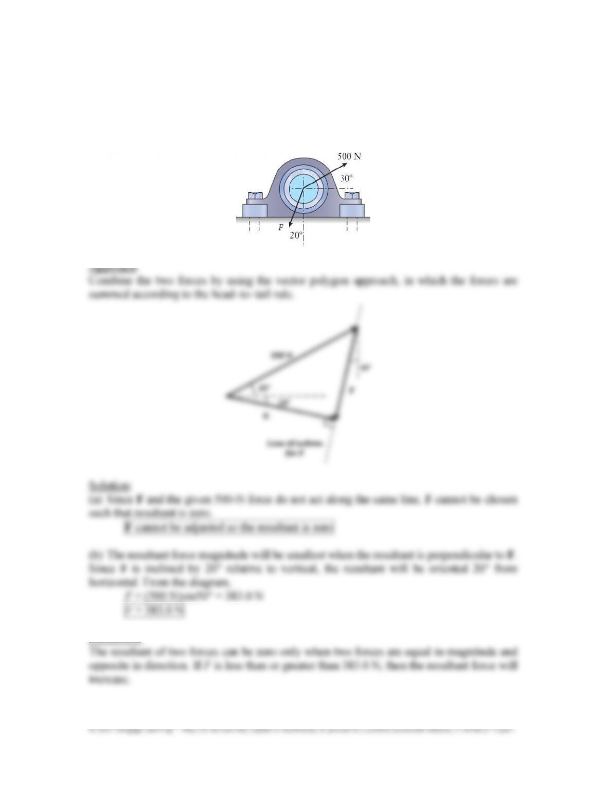
The rolling&element bearings in a pillow&block bearing are contained within the
housing block, which in turn can be bolted to another surface. Two radial forces act on
the pillow block bearing as shown. (a) Can the value of F be adjusted so that the
resultant of the two forces is zero? (b) If not, for what value will the resultant be
minimized?
Discussion:
The resultant of two forces can be zero only when two forces are equal in magnitude and
opposite in direction. If F is less than or greater than 383.0 N, then the resultant force will
increase.
Chapter 4: Forces in Structures and Machines
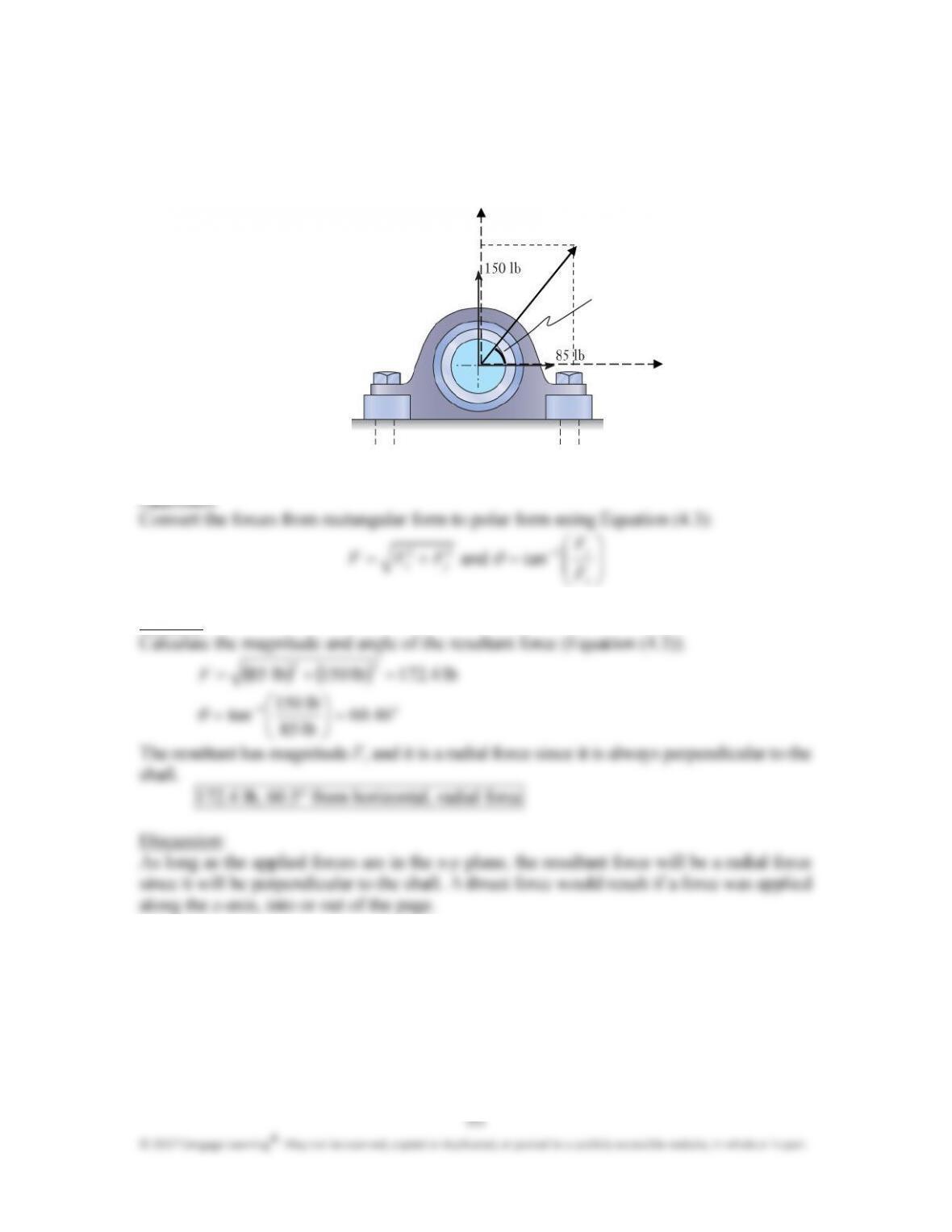
Horizontal and vertical forces act on the pillow&block bearing as it supports a
rotating shaft. Determine the magnitude of the resultant force and its angle relative to
horizontal. Is the resultant force on the bearing a thrust or radial force?
Approach:
y
F
x y
x
F
Solution:
%
%%
%
θ
Chapter 4: Forces in Structures and Machines
96
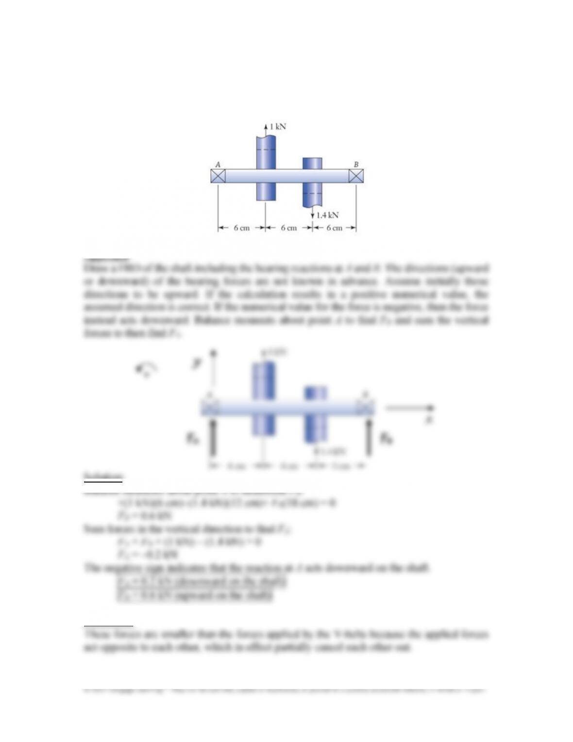
” Ball bearings support a shaft at points A and B. The shaft is used to transmit power
between two V&belts that apply forces of 1 kN and 1.4 kN to the shaft. Determine the
magnitudes and directions of the forces acting on the bearings.
Solution:
Discussion:
These forces are smaller than the forces applied by the V&belts because the applied forces
act opposite to each other, which in effect partially cancel each other out.
Chapter 4: Forces in Structures and Machines
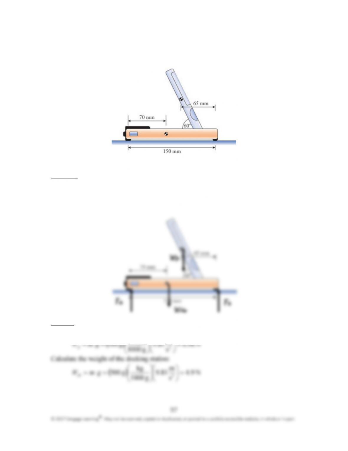
A smart phone is sitting in a docking station. The docking station has a mass of 500
g and the phone, 100 g. Determine the reaction forces at the two supports.
Approach:
Calculate the weight of the player and docking station. Draw a FBD of the player and
docking station including the reaction forces at the supports. Assuming the system is in
static equilibrium, balance moments about the point A to find the support reaction at B and
sum the vertical forces to then find the support reaction at A.
Solution:
Calculate the weight of the player:
m
kg
Calculate the weight of the docking station:
( )
N 94
s
m
819
g 1000
kg
g 005
2
..gmW
ds
=
=⋅=
‘
‘‘
‘
(
((
(
98
© 2017 Cengage Learning
®
. May not be scanned, copied or duplicated, or posted to a publicly accessible website, in whole or in part.
Balance moments about point A to determine F
B
:
( )( ) ( ) ( )( ) ( )
0
mm 1000
m
mm 150
mm 1000
m
mm 1507N .980
mm 1000
m
mm 07N .94 =
+
+−
−
B
F
F
B
= 2.8 N
Sum forces in the vertical direction to find F
A
:
F
A
+ F
B
– (4.9 N) – (0.98 N) = 0
F
A
= 3.1 N
Discussion:
Both reaction forces are positive which is expected because they support the weight of the
player and docking station. Their added magnitudes also equal the added weights of the
player and docking station. F
B
is slightly larger than F
A
because the player is closer to the
support at B.
Chapter 4: Forces in Structures and Machines
99
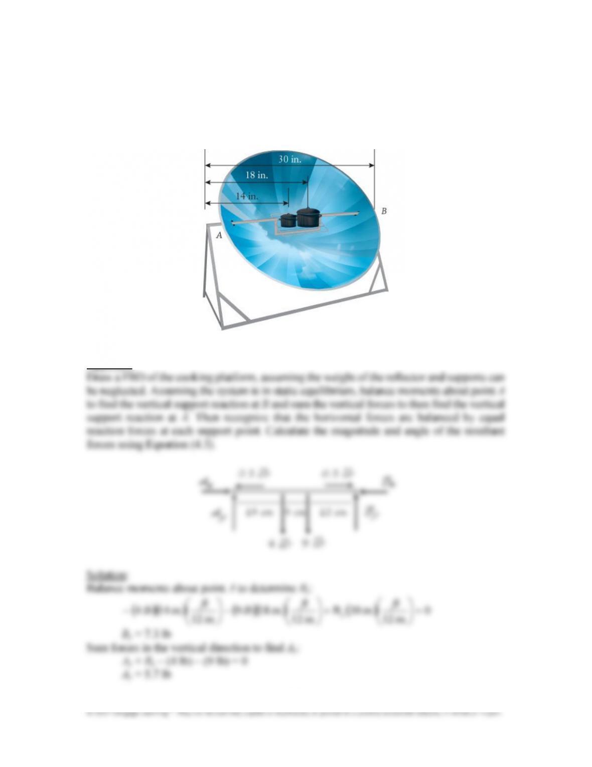
Two pots of food are being cooked on a solar cooker. The smaller pot weighs 4 lb,
and the larger pot weighs 9 lb. Also, due to the thermal expansion of the parabolic
reflector, a horizontal force of 0.5 lb is exerted outward on the two supports. Determine
the magnitude of the resultant force at the two supports, A and B, and the angle of each
resultant force relative to horizontal.
Approach:
Chapter 4: Forces in Structures and Machines
100
© 2017 Cengage Learning
®
. May not be scanned, copied or duplicated, or posted to a publicly accessible website, in whole or in part.
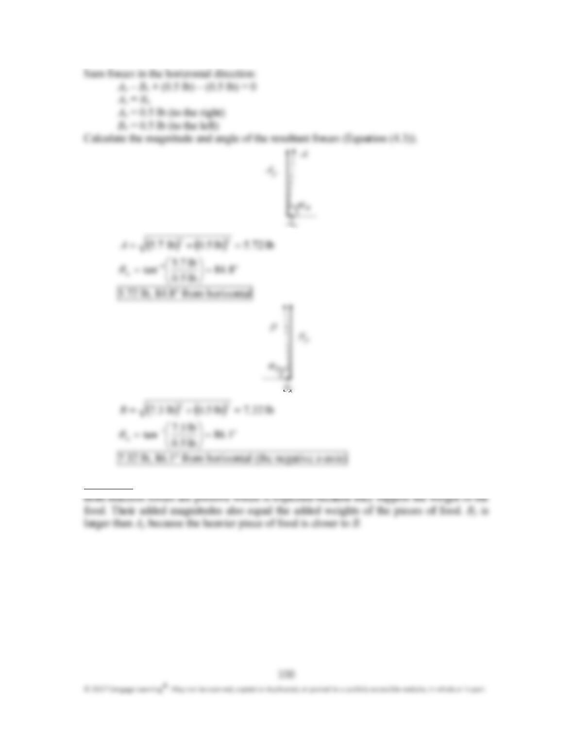
Sum forces in the horizontal direction:
A
x
– B
x
+ (0.5 lb) – (0.5 lb) = 0
A
x
= B
x
A
x
= 0.5 lb (to the right)
B
x
= 0.5 lb (to the left)
Calculate the magnitude and angle of the resultant forces (Equation (4.3)).
( ) ( )
lb 725lb 0.5 lb75
22
..A
=+=
o1
A
884
lb .50
lb .75
tan .=
=
−
θ
5.72 lb, 84.8° from horizontal
( ) ( )
lb 327lb 0.5 lb37
22
..B
=+=
o1
A
186
lb .50
lb .37
tan .=
=
−
θ
7.32 lb, 86.1° from horizontal (the negative x&axis)
Discussion:
Chapter 4: Forces in Structures and Machines
101
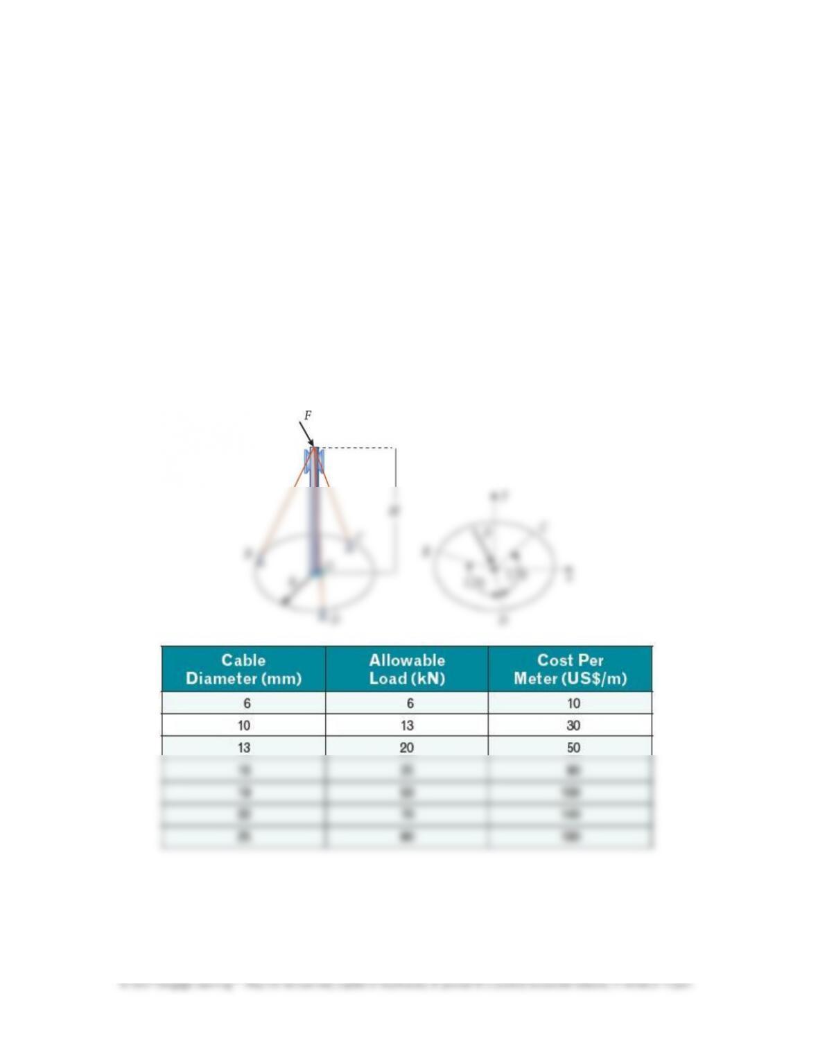
#: Considering both safety and cost, determine the best cable option from Table
P4.35 to support a cellular tower of a given height, H = 30 m, and maximum horizontal
force, F = 20 kN. Also specify the radius R (to the nearest meter) of the supports at
point B, C, and D measured from the base of the structure; the diameter of the steel
cable chosen; and the total cost of the cable used. Present your approach, solution, and
discussion in a formal report. Note the following starting assumptions your group
should make (you will most likely have more assumptions):
•The force remains horizontal and acts at the top of the tower.
•The center of the base of the tower acts as the origin, O.
•The direction of the force in the figure is arbitrary. Your cable structure should be
designed to withstand this force acting at any angle on the tower.
•The cables support the tower only in tension. Otherwise, they are slack.
•The tower and supports are all on a flat horizontal plane.
•Supports B, C, and D should all be located at a distance, R, from the base and
equally spaced from each other.
•Neglect the weight of the cables.
Chapter 4: Forces in Structures and Machines
102
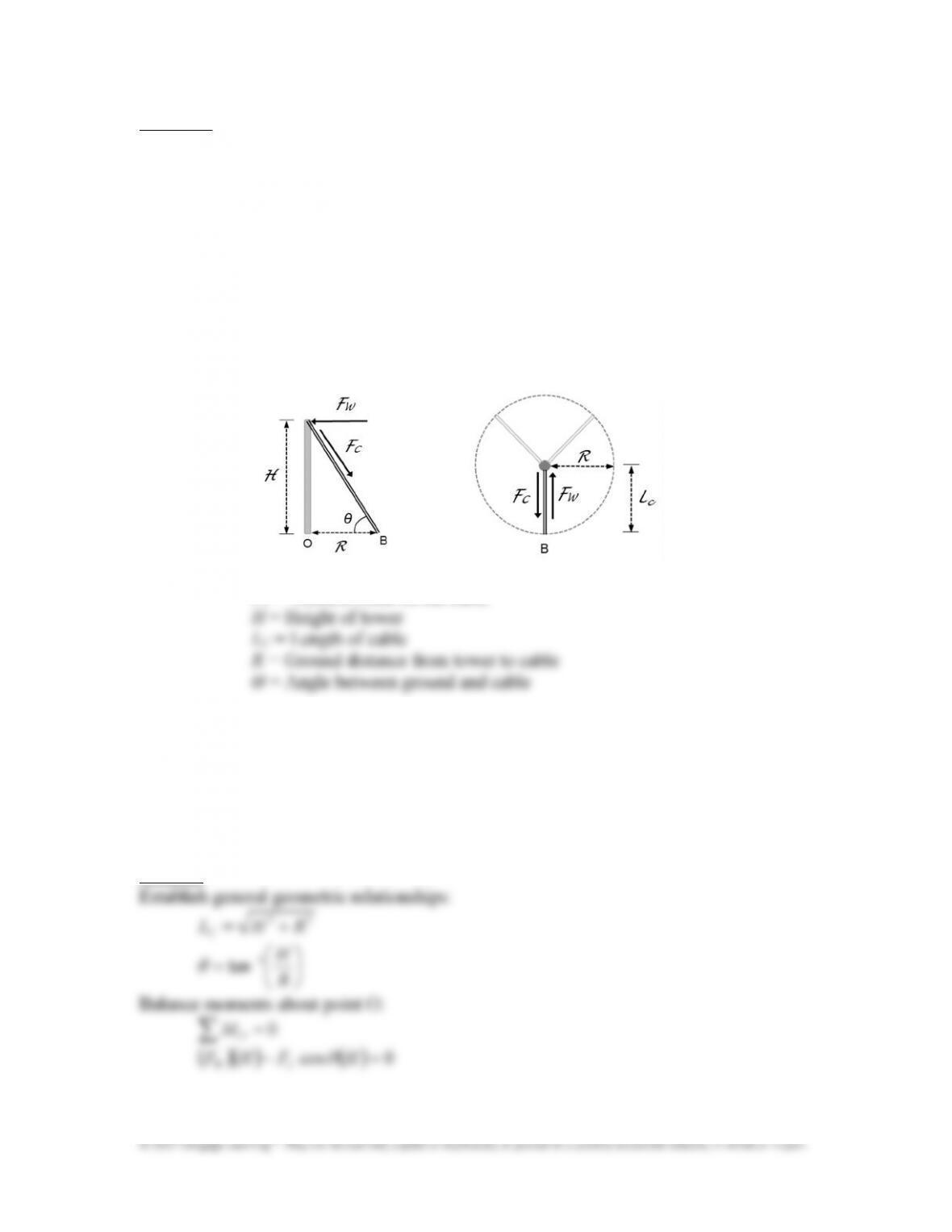
Approach:
From the given assumptions, the cables only act in tension. Therefore, the worst case
scenario is designed for when the wind loading is directly aligned with one of the three
cables. In this scenario, two of the cables are in slack and only one cable is supporting the
entire wind load, as long as the three cables are equally spaced from each other around the
tower (a given assumption).
Draw a FBD of this scenario and take moments around the base of the tower, O. Without
knowing the cable lengths or the distance from the base of the tower, the free body diagram
is kept in symbolic form. Then, the cable options from Table P4.35 are tested for their
ability to support the maximum load. The lowest cost option that will support the worst
case loading scenario is chosen.
F
W
= Force of the wind loading
F
C
= Tension force on the cable
Of these six variables, two are known (F
W
and H). Of the remaining four, only one of them
is independent. That is, once one of the variables is set, the remaining three can be
determined from geometric or moment balance relationships. However, there is not enough
information given in the problem to solve for the remaining variables. The maximum load
information from Table P4.35 must be used to find possible design options that are
feasible.
Solution:
CW
Chapter 4: Forces in Structures and Machines
103
© 2017 Cengage Learning
®
. May not be scanned, copied or duplicated, or posted to a publicly accessible website, in whole or in part.
(
)
(
)
(
)
HFHF
CW
θ
cos=
θ
cos
CW
FF =
C
W
F
F
=
θ
cos
C
W
F
F
R
H=
−1
tancos
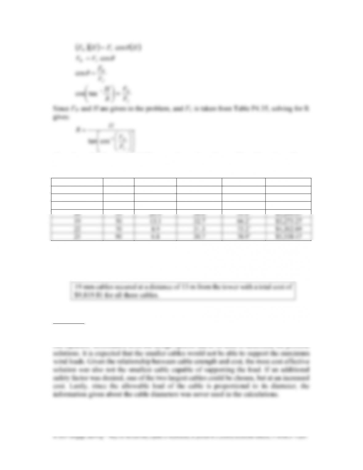
Since F
W
and H are given in the problem, and F
C
is taken from Table P4.35, solving for R
gives:
=
−
C
W
F
F
H
R
1
costan
The values of F
C
from Table P4.35 are used to evaluate the possible cable options. The
following table summarizes the resulting options.
Diameter (
mm)
(
)
(
)
ℎ
(
)
Θ (deg)
/
!
$
6 6 not feasible not feasible not feasible not feasible
10 13 not feasible not feasible not feasible not feasible
13 20 not feasible not feasible not feasible not feasible
The first three cable options are simply not strong enough to support the worst case load.
However, the largest four cables are all strong enough given their maximum allowable
load. Based on their overall cost, the 19 mm cable is the most cost effective solution.
Discussion:
Design problems are typically characterized as being under constrained. In other words,
they have more unknowns than equations. In this case, there are two unknowns and only
Chapter 4: Forces in Structures and Machines
104