
Chapter 4: Forces in Structures and Machines
59
Chapter 4: Forces in Structures and Machines
60
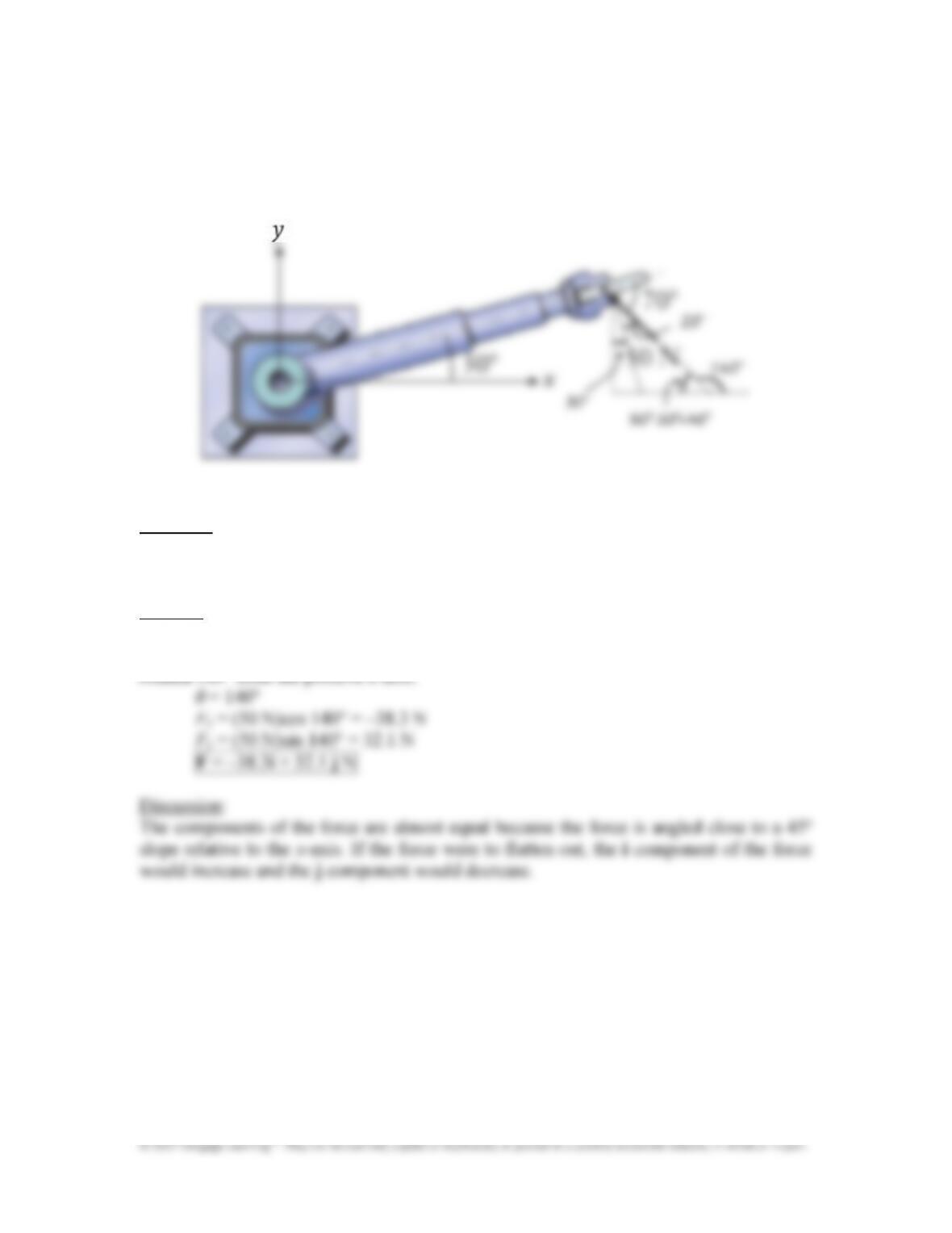
The cylindrical coordinate robot on a factory’s assembly line is shown in a top view.
The 50 N force acts on a workpiece being held at the end of the robot‘s arm. Express the
50 N force as a vector in terms of unit vectors and that are aligned with the x& and
y&axes.
Approach:
Find the angle θ between the force and the x&axis. Calculate rectangular components using
F=50 N and Equation (4.2): F
x
= Fcosθ and F
y
= Fsinθ
Solution:
The 50&N force makes a 20° angle with a line perpendicular to the robot arm, and a 50°
angle relative to vertical, since the arm itself is inclined by 30°. The force is therefore
rotated 140° from the positive x&axis.
Chapter 4: Forces in Structures and Machines
61
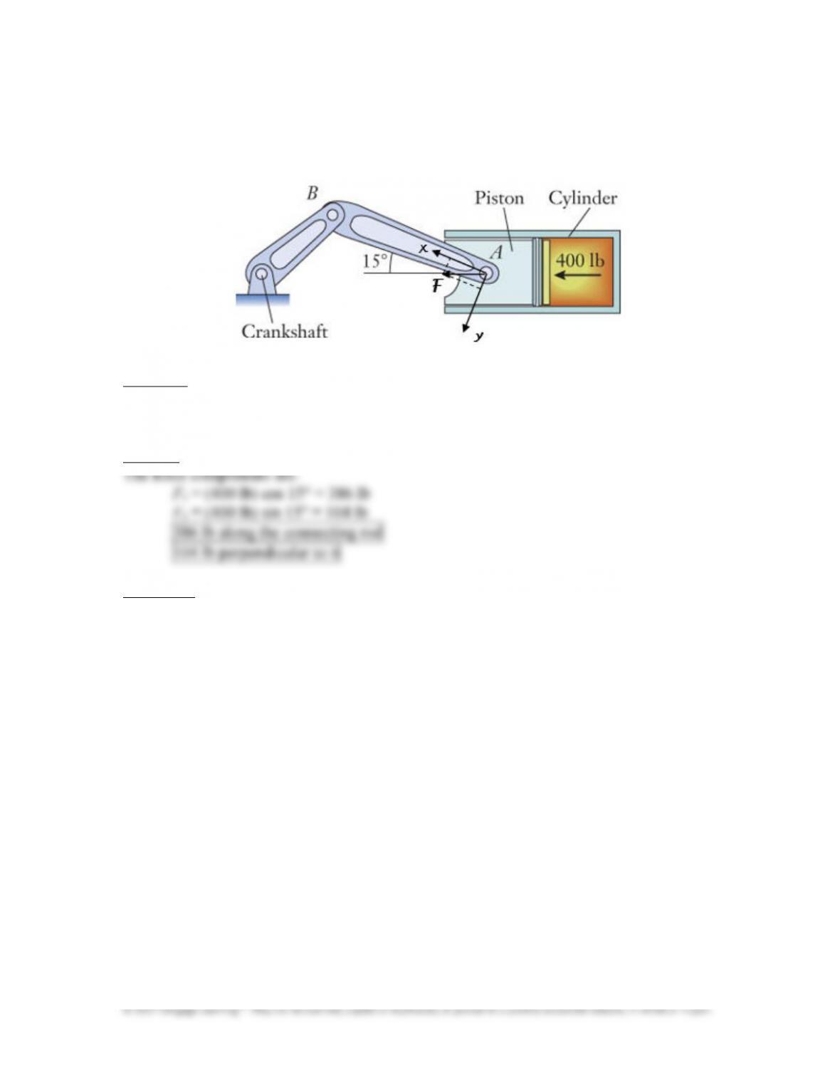
During the power stroke of an internal combustion engine, the 400 lb pressure force
pushes the piston down its cylinder. Determine the components of that force in the
directions along and perpendicular to the connecting rod AB.
Approach:
Use the x–y coordinates attached to the connecting rod as shown. Find the rectangular
components using Equation (4.2): F
x
= Fcosθ and F
y
= Fsinθ with F = 400 lb and θ = 15°.
Solution:
Discussion:
The force along the connecting rod is larger since the angle between the force and
connecting road is smaller than the angle between the force and the perpendicular to the
connecting road. As the piston moves to the left, the force along the connecting rod will
decrease and the force perpendicular to it will increase.
Chapter 4: Forces in Structures and Machines
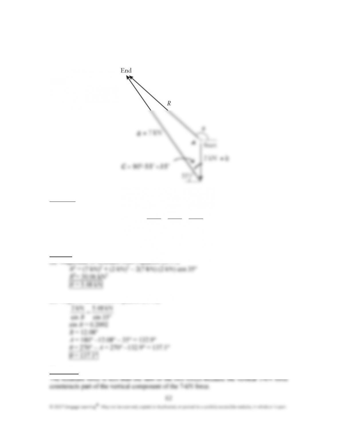
A vector polygon for summing 2 kN and 7 kN forces is shown. Determine (a) the
magnitude R of the resultant by using the law of cosines and (b) its angle of action θ by
using the law of sines.
Approach:
Apply the laws of cosines and sines from Appendix B:
c
2
= a
2
+ b
2
– 2ab cos c and
sin sin sin
a b c
A B C
= =
where A, B, and C are interior angles, and a, b, and c are side lengths. Angle C = 90° – 55°
= 35°.
Solution:
(b) Angle of action from Equation (B.16):
5
3
kN .485
kN 2 =
Discussion:
=
= –=
=
=
Chapter 4: Forces in Structures and Machines
63
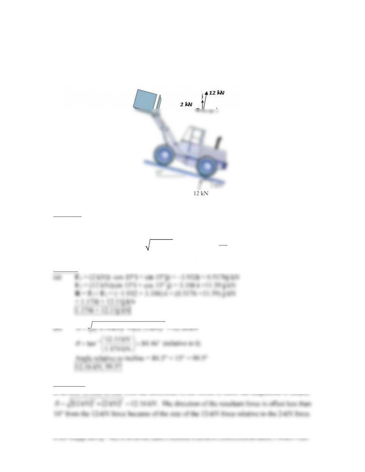
A hydraulic&lift truck carries a shipping container on the inclined loading ramp in a
warehouse. The 12 kN and 2 kN forces act on a rear tire as shown in the directions
perpendicular and parallel to the ramp. (a) Express the resultant of those two forces as a
vector using the unit vectors and . (b) Determine the magnitude of the resultant and
its angle relative to the incline.
Approach:
Use the vector algebra method and combine the two forces using Equations (4.4)–(4.6).
Find the magnitude and angle of action of the resultant using Equation (4.7):
2 2
x y
R R R
= + and
1
tan
y
x
R
R
θ
−
=
Solution:
22
Discussion:
Chapter 4: Forces in Structures and Machines
64
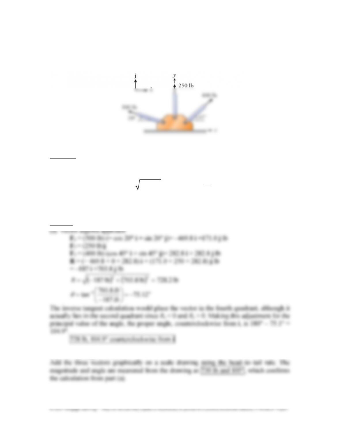
Three tension rods are bolted to a gusset plate. Determine the magnitude and
direction of their resultant. Use the (a) vector algebra and (b) vector polygon methods.
Compare the answers from the two methods to verify the accuracy of your work.
Approach:
Using the unit vectors, combine the horizontal and vertical components by the vector
algebra method using Equations (4.4)–(4.6). Apply Equation (4.7):
2 2
x y
R R R
= + and
1
tan
y
x
R
R
θ
−
=
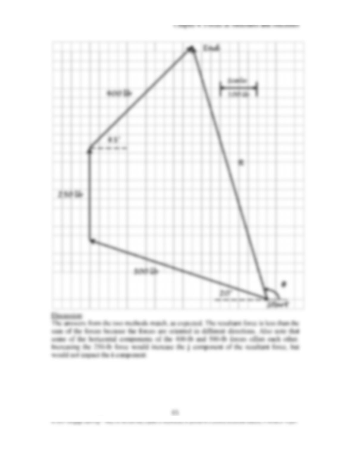
to find the resultant’s magnitude and angle of action. Make a scale drawing of the vector
polygon and measure the resultant’s length and angle graphically.
Solution:
(b) Vector polygon method
65
© 2017 Cengage Learning
®
. May not be scanned, copied or duplicated, or posted to a publicly accessible website, in whole or in part.
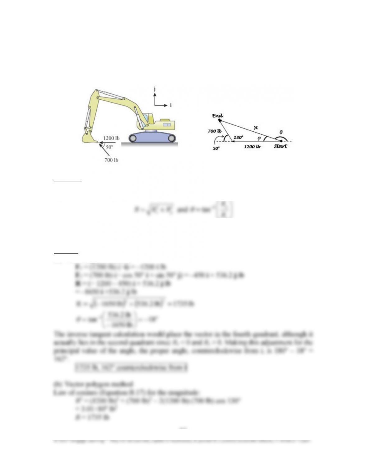
Chapter 4: Forces in Structures and Machines
The bucket of the excavator at a construction site is subjected to 1200 lb and 700 lb
digging forces at its tip. Determine the magnitude and direction of their resultant. Use
the (a) vector algebra and (b) vector polygon methods. Compare the answers with the
two methods to verify the accuracy of your work.
Approach:
Using the unit vectors, combine the horizontal and vertical components by the vector
algebra method using Equations (4.4)–(4.6). Apply Equation (4.7)
2 2
1
y
R
−
x
R
Chapter 4: Forces in Structures and Machines
67
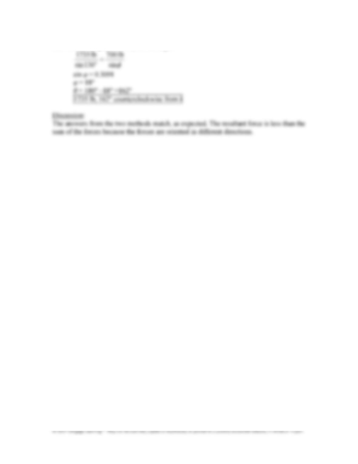
Law of sines (Equation B.16) for the angle:
lb 007
lb 7351
o
=
Chapter 4: Forces in Structures and Machines
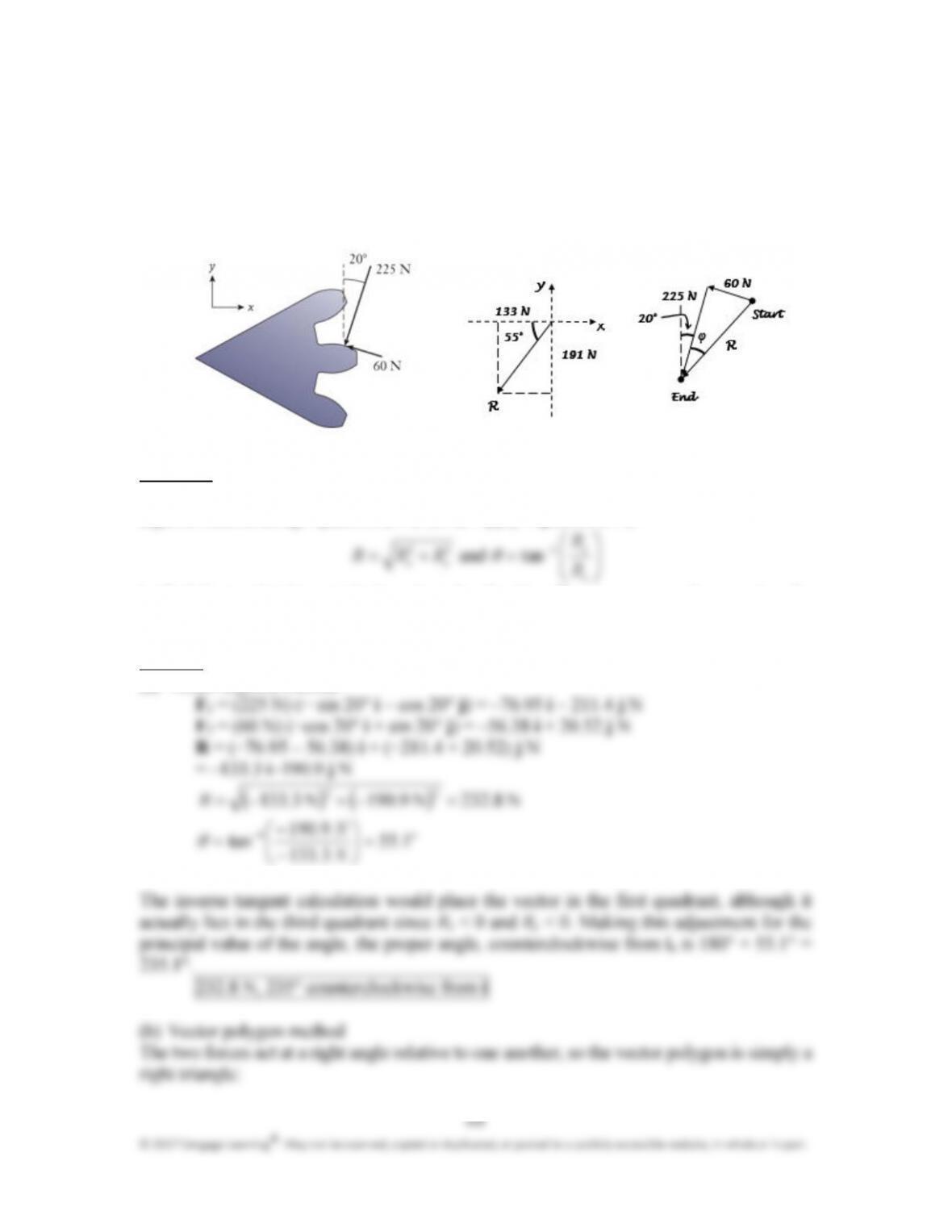
Forces of 225 N and 60 N act on the tooth of a spur gear. The forces are
perpendicular to one another, but they are inclined by 20° relative to the x–y
coordinates. Determine the magnitude and direction of their resultant. Use the (a)
vector algebra and (b) vector polygon methods. Compare the answers from the two
methods to verify the accuracy of your work.
Approach:
Using the unit vectors, combine the horizontal and vertical components by the vector
algebra method using Equations (4.4)–(4.6). Apply Equation (4.7):
y
x y
x
R
R
to find the resultant‘s magnitude and angle of action. Draw a vector polygon using the
head–to–tail rule and apply laws of geometry to determine the magnitude and angle.
Solution:
(a) Vector algebra method
3133
N.
−
Chapter 4: Forces in Structures and Machines
69
© 2017 Cengage Learning
®
. May not be scanned, copied or duplicated, or posted to a publicly accessible website, in whole or in part.
( ) ( )
N 8232N 06N 252
22
.R
=+=
o1
914
N 252
N 06
tan .=
=
−
ϕ
The resultant R is directed 20° + 14.9° = 34.9° from vertical, and 180° + (90° – 34.9°) =
235.1° from the x–axis.
232.8 N, 235° counterclockwise from
Discussion:
The answers from the two methods match, as expected. This problem illustrates that the
law of cosines simplifies to the Pythagorean theorem when the forces are perpendicular to
each other.
Chapter 4: Forces in Structures and Machines
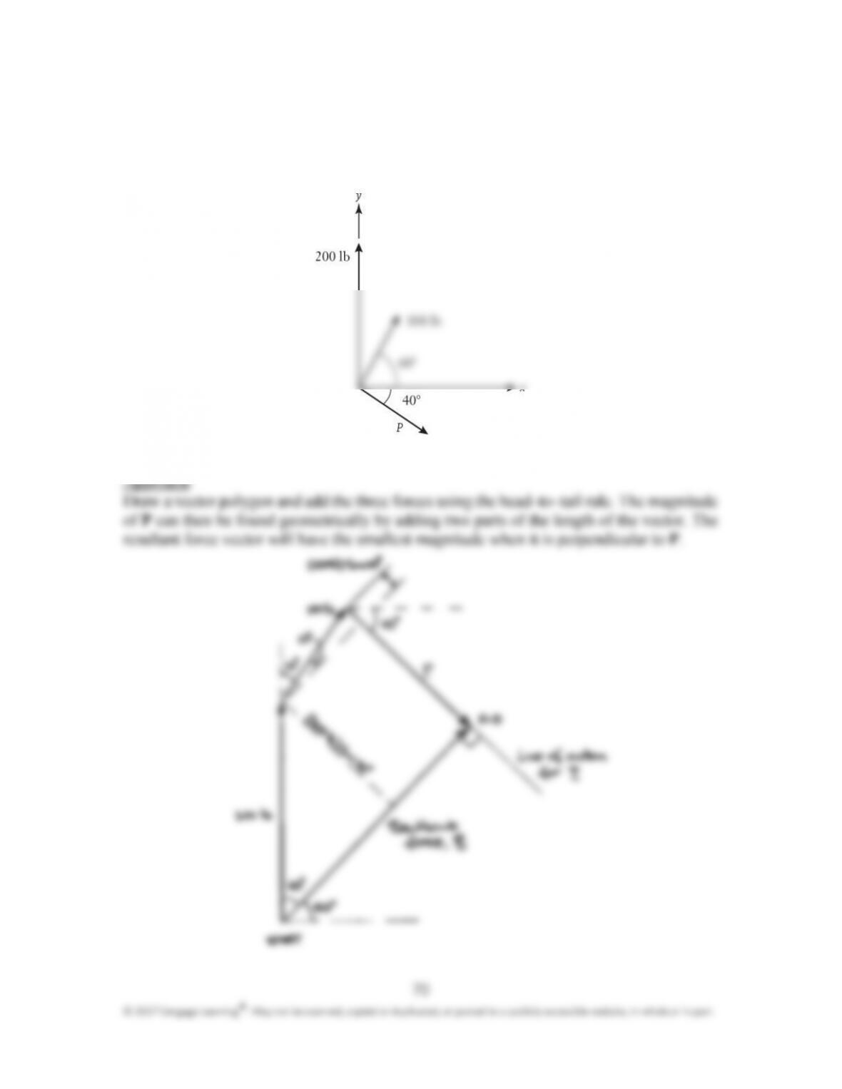
The three forces (magnitudes 100 lb, 200 lb, and P) combine to produce a resultant
. The three forces act in known directions, but the numerical value of P is unknown.
(a) What should the magnitude of be so that the resultant is a small as possible? (b)
For that value, what angle does the resultant make relative to the positive x&axis?
Chapter 4: Forces in Structures and Machines
71
Solution:
(a) From the diagram,
Chapter 4: Forces in Structures and Machines
72
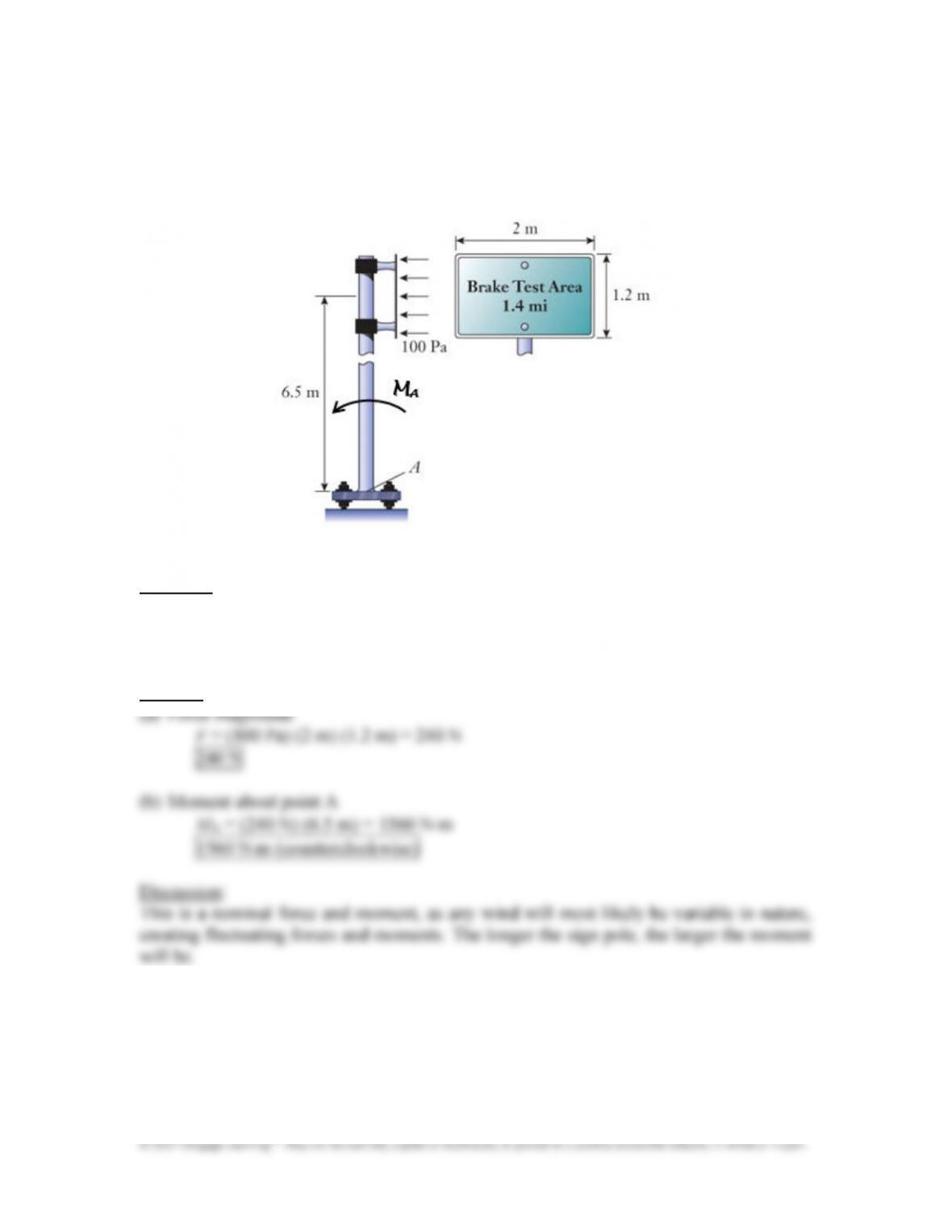
Resulting from a light wind, the air pressure imbalance of 100 Pa acts across the 1.2
m by 2 m surface of the highway sign. (a) Calculate the magnitude of the force acting
on the sign. (b) Calculate the moment produced about point A on the base of the sign
pole.
Approach:
The magnitude of the force acting on the sign is the product of the pressure imbalance and
the sign’s area. Find the moment about A using Equation (4.8) M
A
= Fd assuming the force
acts at the center of the sign. Recall from Table 3.2 that 1 Pa = 1 N/m
2
.
Solution:
Chapter 4: Forces in Structures and Machines
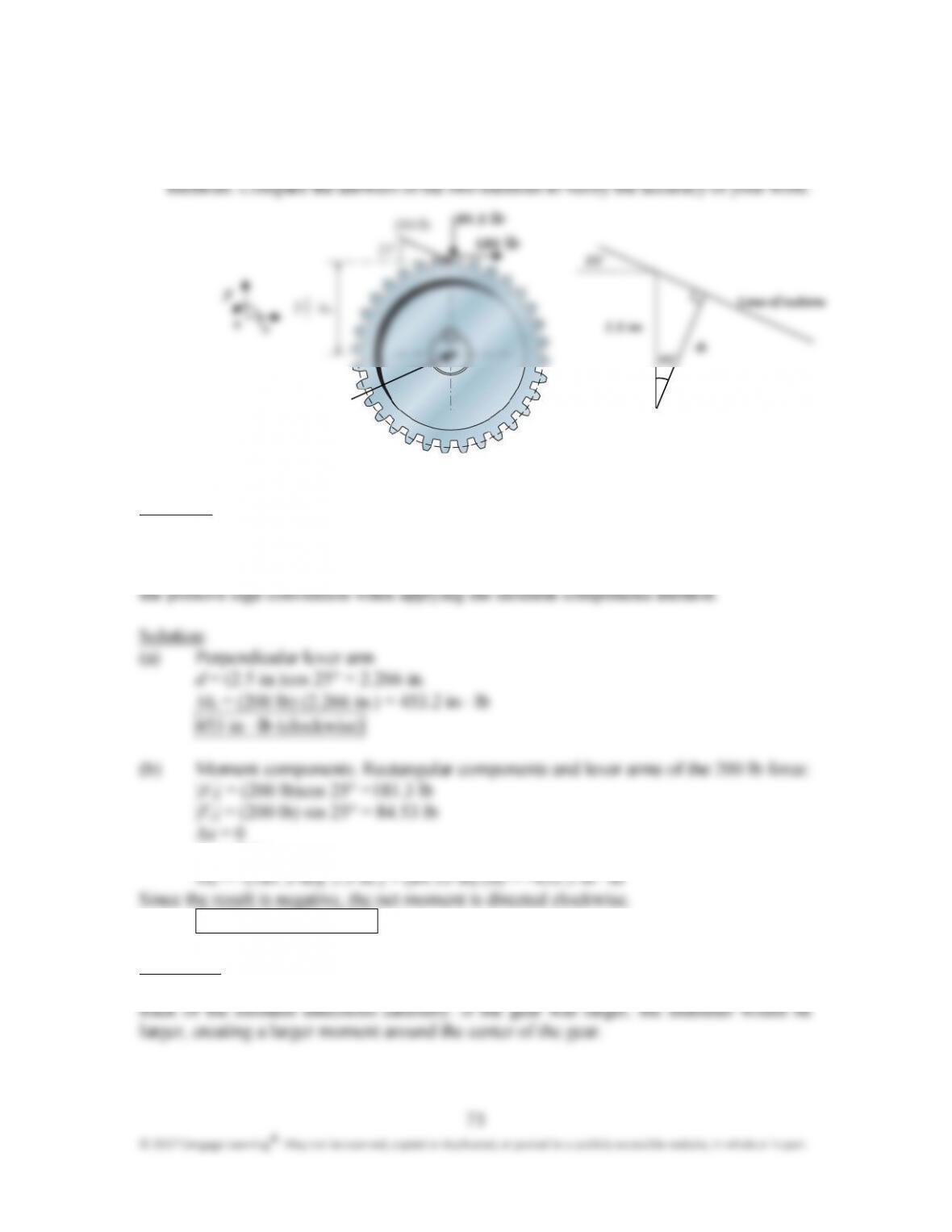
The spur gear has a pitch of 2.5 in. During a geartrain’s operation, a 200 lb meshing
force acts at 25° relative to horizontal. Determine the moment of that force about the
center of the shaft. Use the (a) perpendicular lever arm and (b) moment components
Approach:
A component of the force is directed radially toward the shaft’s center, and it contributes no
moment about that point. Apply Equation (4.8) M = Fd and find the perpendicular lever
arm distance d from the gear’s geometry. Then use Equation (4.9) M = ±F
x
Jy ± F
y
Jx and
Jy = 2.5 in.
453.2 in ⋅ lb (clockwise)
Discussion:
The methods give the same result, as expected. Both methods require an engineer to keep
track of the moment directions carefully. If the gear was larger, the diameter would be
larger, creating a larger moment around the center of the gear.
Chapter 4: Forces in Structures and Machines
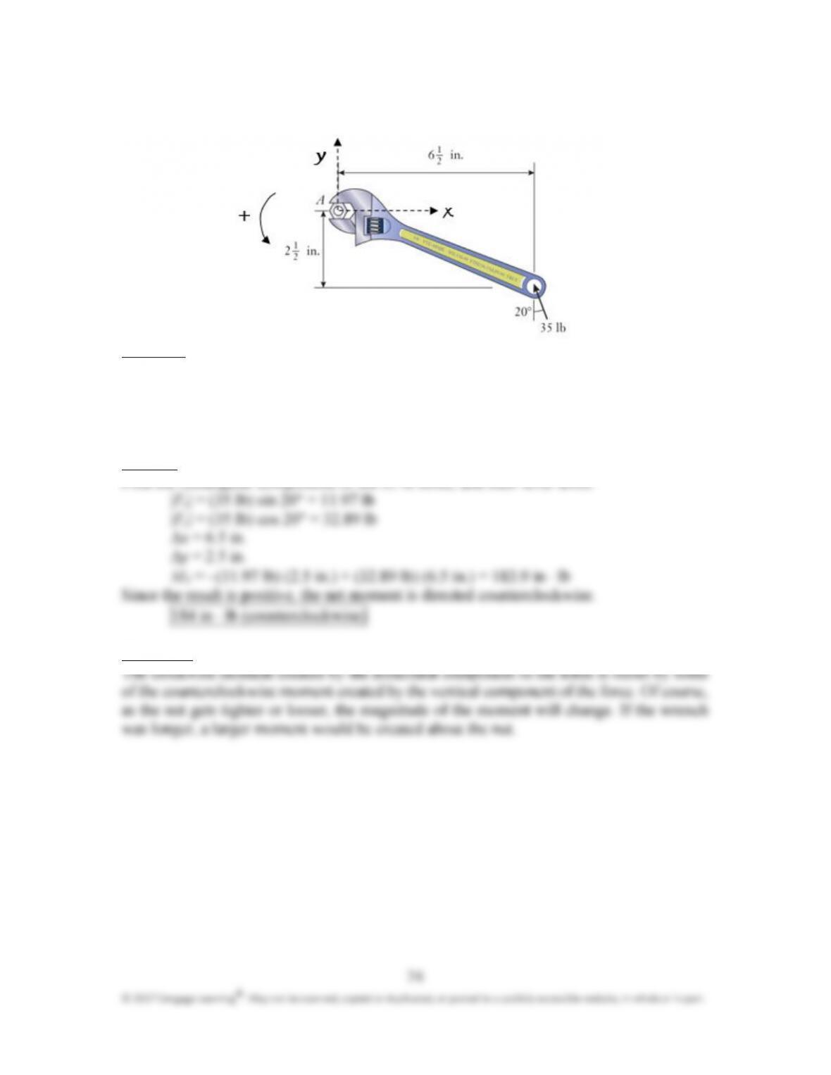
Determine the moment of the 35 lb force about the center A of the hex nut.
Approach:
Find the rectangular components of the force, and their lever arms. Then apply Equation
(4.9):
M = ±F
x
Jy ± F
y
Jx
Use the x&y coordinates and positive sign convention shown on the drawing.
Solution:
Find the rectangular components of the 35 lb force, and their lever arms:
Discussion:
Chapter 4: Forces in Structures and Machines
75
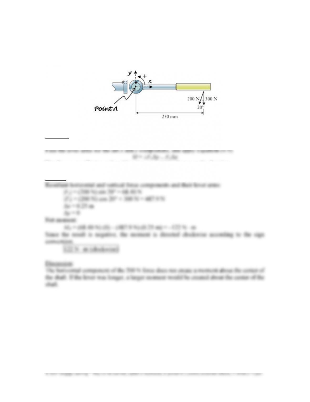
Two construction workers pull on the control lever of a frozen valve. The lever
connects to the valve’s stem through the key that fits into partial square grooves on the
shaft and handle. Determine the net moment about the center of the shaft.
Approach:
Find the rectangular components of the 200 N force, and combine with the 300 N force.
Use the x&y coordinates and positive sign convention shown on the drawing.
Solution:
Chapter 4: Forces in Structures and Machines
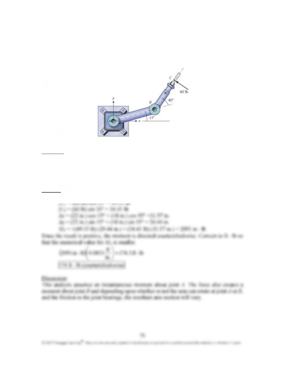
Gripper C of the industrial robot is accidentally subjected to the 60 lb side load,
directed perpendicular to BC. The lengths of the robot’s links are AB = 22 in. and BC =
18 in. By using the moment components method, determine the moment of this force
about the center of joint A.
Approach:
Find the rectangular components of the force, and their lever arms. Then apply Equation
(4.9):
M = ±F
x
Jy ± F
y
Jx
Use the x–y coordinates and positive sign convention shown on the drawing.
Solution:
Resultant horizontal and vertical force components and their lever arms:
Chapter 4: Forces in Structures and Machines
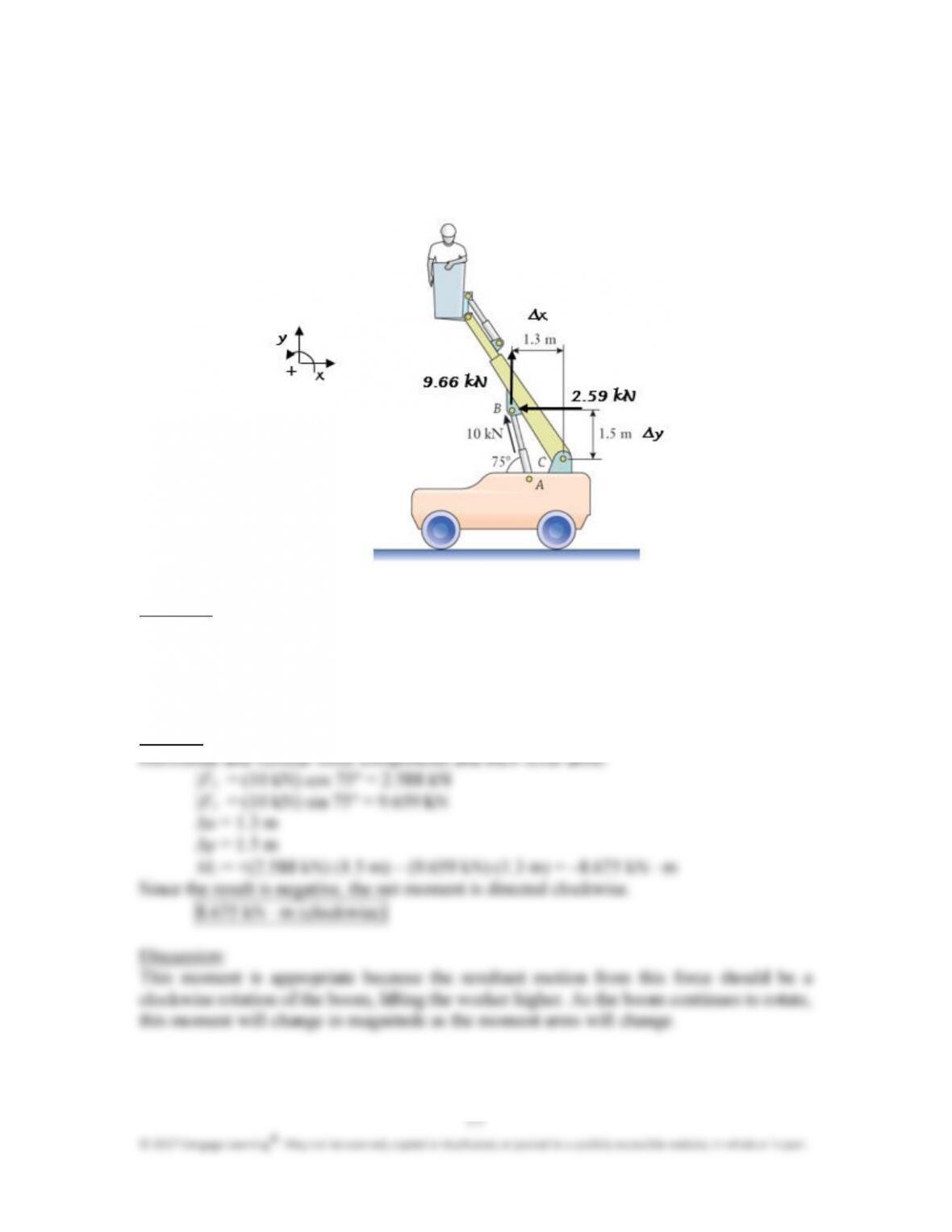
The mobile boom lift is used in construction and maintenance applications. The
hydraulic cylinder AB exerts a 10 kN force on joint B which is directed along the
cylinder. By using the moment components method, calculate the moment of this force
about the lower support point C of the boom.
Approach:
Find the rectangular components of the force, and their lever arms. Then apply Equation
(4.9):
M = ±F
x
Jy ± F
y
Jx
Use the x–y coordinates and positive sign convention shown on the drawing.
Solution:
Chapter 4: Forces in Structures and Machines
78
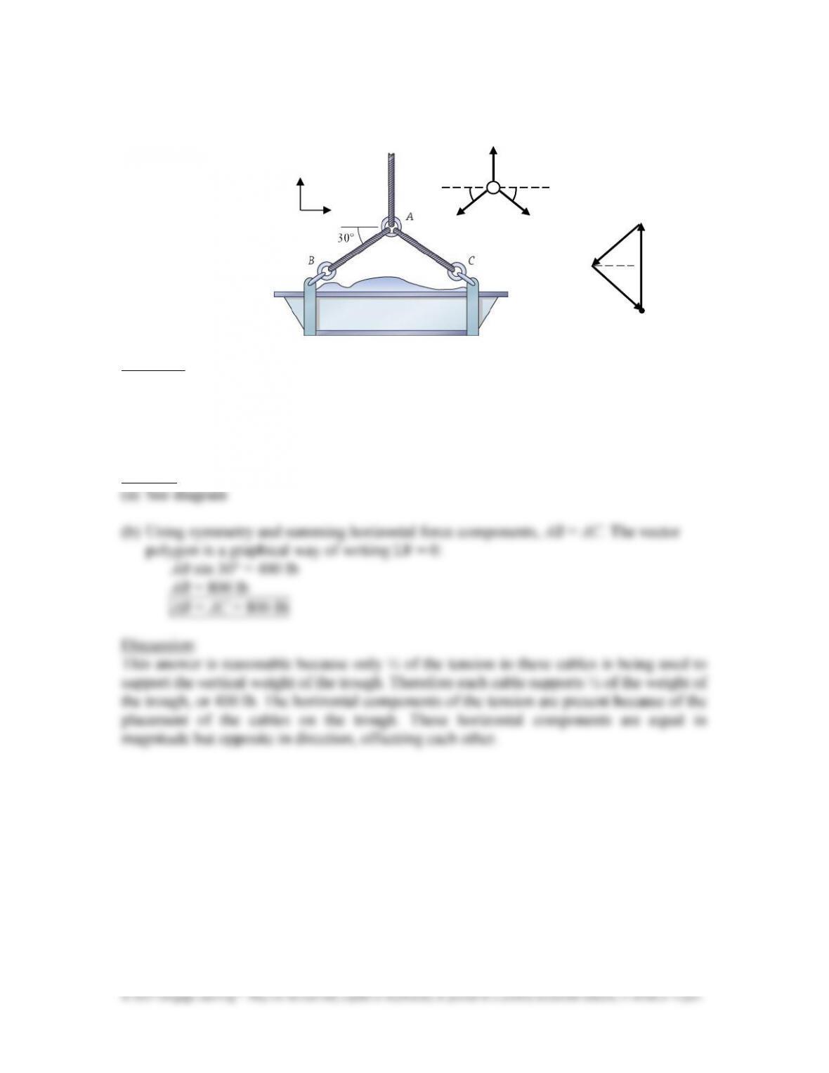
The trough of concrete weighs 800 lb. (a) Draw a free body diagram of the cable’s
ring A. (b) Treating the ring as a particle, determine the tension in cables AB and AC.
Approach:
The three tension forces act along the cables. Sum the forces on a vector polygon using the
head–to–tail rule. Assuming the suspension system is in static equilibrium, the polygon’s
start and end points are the same since there is zero resultant force acting on the ring. The
weights of the cables and ring are not considered.
Solution:
!
! !
!