Chapter 4: Forces in Structures and Machines
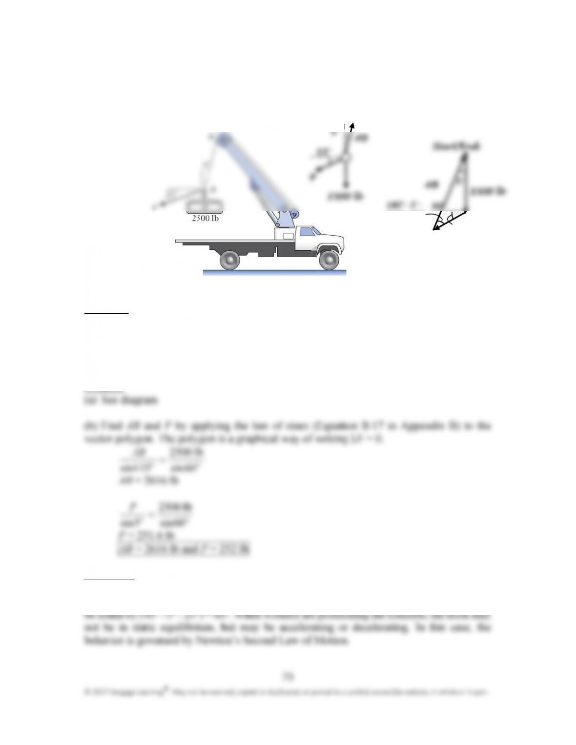
Cable AB of the boom truck is hoisting the 2500 lb section of precast concrete. A
second cable is under tension P, and workers use it to pull and adjust the position of the
concrete section as it is being raised. (a) Draw a free body diagram of hook A, treating it
as a particle. (b) Determine P and the tension in cable AB.
Approach:
The two tension forces act along the cables. Sum the forces on a vector polygon using the
head–to–tail rule. Assuming the hook is in static equilibrium, the polygon’s start and end
points are the same since there is zero resultant force acting on the hook. The weights of the
cable and hook are not considered.
Solution:
Discussion:
It makes sense that the tension in AB is much larger than P because AB is supporting all the
weight of the concrete section. The angle between AB and P in the vector polygon can also
o
o
o
o
not be in static equilibrium, but may be accelerating or decelerating. In this case, the
behavior is governed by Newton’s Second Law of Motion.
!
! !
!
= “
““
“

Chapter 4: Forces in Structures and Machines
80
Solve the problem of Example 4.5 by using the force components method. Replace
the polar representation of the anchor strap’s tension by the horizontal and vertical
components T
x
and T
y
, and solve for them. Use your solution for T
x
and T
y
to determine
the magnitude T and direction θ of the anchor strap’s tension.
Approach:
Use the FBD and coordinate system shown in the figure. The tension force is ! = T
x
+ T
y
. Assume the strap system is in equilibrium and then write the equilibrium equations in x
and y using the vector algebra approach.
Solution:
Write the given forces as vectors:

Chapter 4: Forces in Structures and Machines
81
Discussion:
It makes sense that the horizontal component of the tension is larger than the vertical
component since the tension in the lap strap is completely horizontal. If the tension in the
lap strap were to increase, then the angle of the resultant force would decrease (it would get
closer to being horizontal).
Chapter 4: Forces in Structures and Machines
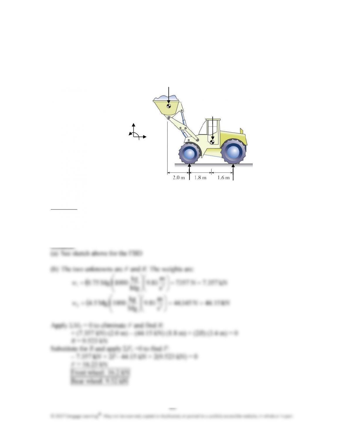
” The front loader of mass 4.5 Mg is shown in side view as it lifts a 0.75 Mg load of
gravel. (a) Draw a free body diagram of the front loader. (b) Determine the contact
forces between the wheels and the ground. (c) How heavy a load can be carried before
the loader will start to tip about its front wheels?
Approach:
Let F and R be the contact forces on one front and one rear tire. There are two unknowns.
Assuming the system is in static equilibrium, write a force balance in the vertical direction
and a moment balance about the front wheels.
#
##
#
#
##
#
$
$$
$
%
%%
%
83
© 2017 Cengage Learning
®
. May not be scanned, copied or duplicated, or posted to a publicly accessible website, in whole or in part.
(c) The two unknowns are w
1
and F. At the condition of tipping, R = 0. Apply Σ M
A
= 0 to
eliminate F and find w
1
+ w
1
(2.0 m) – (44.15 kN)(1.8 m)=0
w
1
= 39.74 kN
39.7 kN
Chapter 4: Forces in Structures and Machines
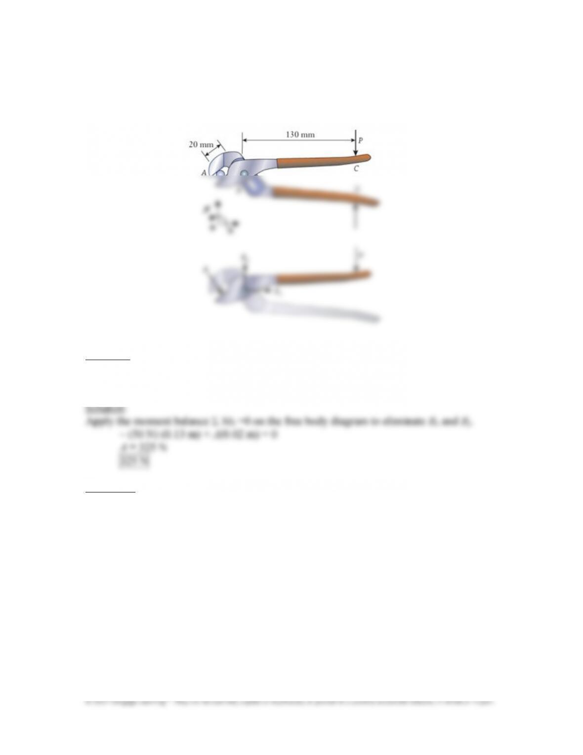
84
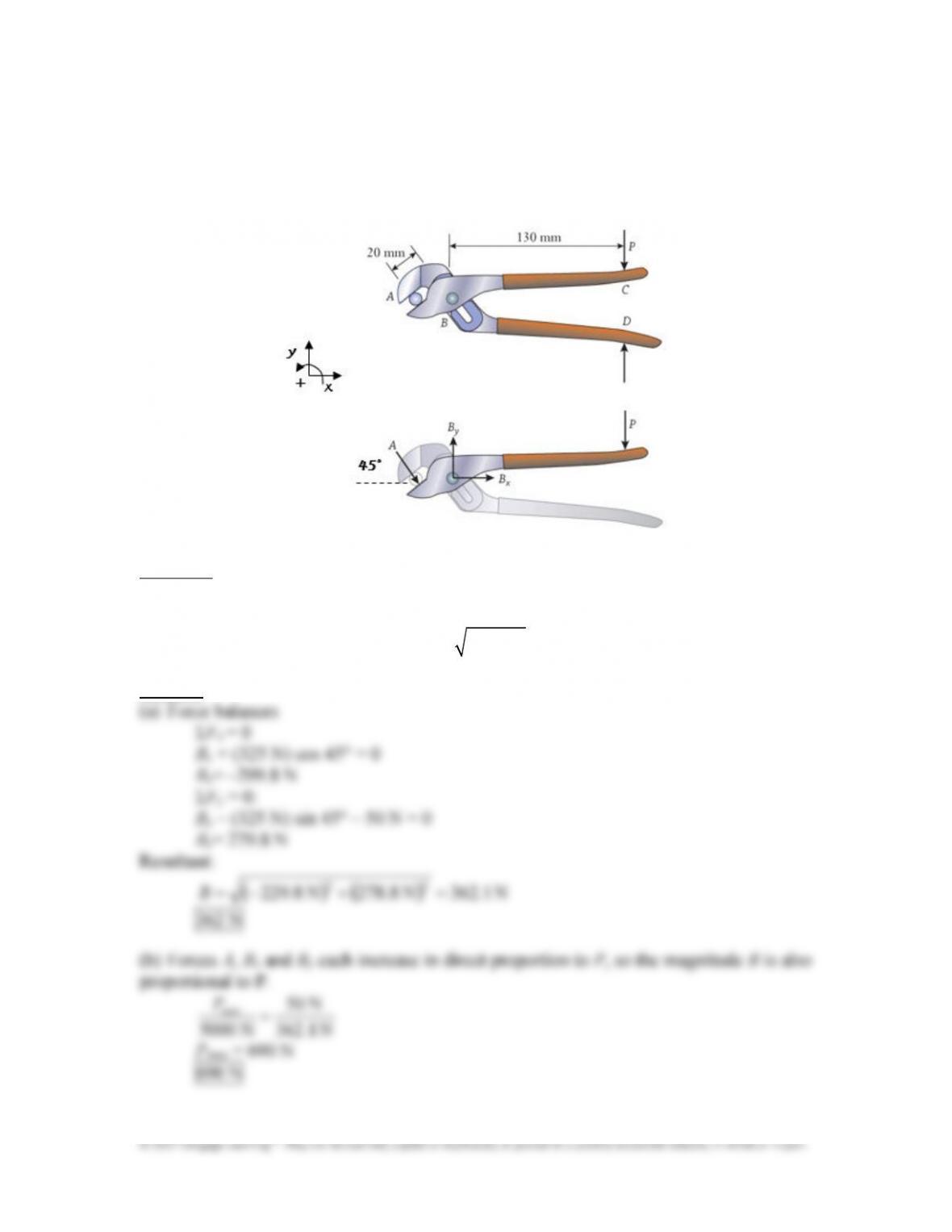
Adjustable pliers hold a round metal bar as a machinist grips the handles with P =
50 N. Using the free body diagram shown for the combined lower jaw and upper
handle, calculate the force A that is applied to the bar.
Approach:
Assuming the system is in static equilibrium and with a moment balance about point B, the
unknowns B
x
and B
y
are eliminated.
Discussion:
If the lower jaw handle was isolated instead, the same force would be applied to the other
side of the bar. If the pliers handle was longer, the force applied would be greater.
Chapter 4: Forces in Structures and Machines
85
Refer to P4.21. (a) Measure the angle of force A directly from the diagram and use it
to find the magnitude of the force at hinge B. (b) A design condition is that the force at
B should be less than 5 kN. What is the maximum force that a machinist can apply to
the handle before that condition is reached?
Approach:
From P4.21, A = 325 N. Measure the angle of A as 45°. Sum the horizontal and vertical
force components on the FBD to find B
x
and B
y
. Find the force‘s magnitude using:
2 2
x y
B B B
= +
Solution:
Chapter 4: Forces in Structures and Machines
86
Discussion:
Chapter 4: Forces in Structures and Machines
87
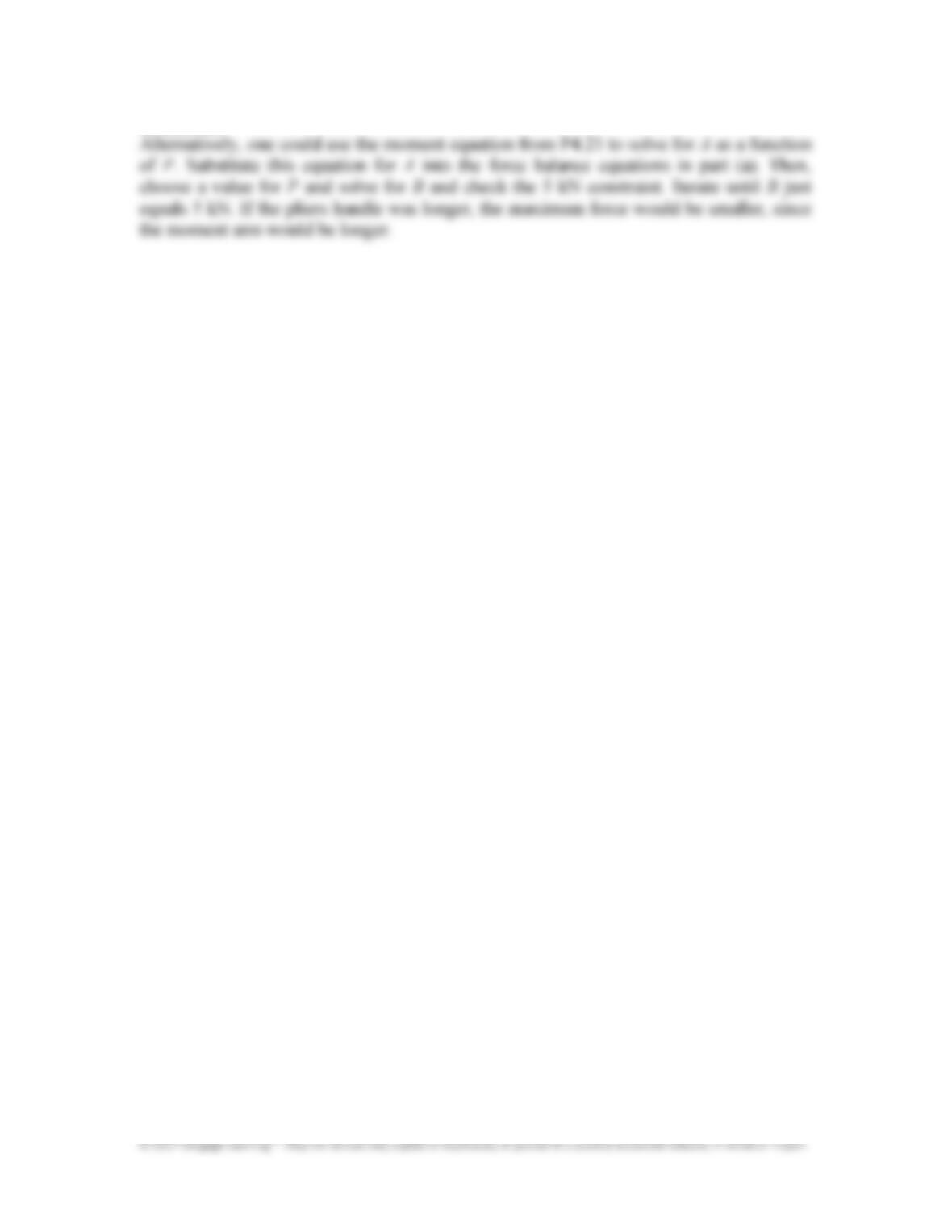
A pair of large hydraulically operated shears is attached to the end of the boom on
an excavator. The shear is used for cutting steel pipe and I&beams during demolition
work. Hydraulic cylinder AB exerts an 18 kN force on the upper jaw. (a) Complete the
free body diagram for the upper jaw, which has been only partially drawn. (b)
Determine the cutting force F being applied to the pipe.
Approach:
Assuming the system is in static equilibrium, use the FBD and balance moments about
point C to eliminate unknowns C
x
,
and C
y
, and solve for F.
Solution:
Discussion:
The cutting force is larger than the applied hydraulic force which makes sense. This is
because the moment arm to the cutting force about C is smaller than the moment arm to the
hydraulic force.
Chapter 4: Forces in Structures and Machines
88
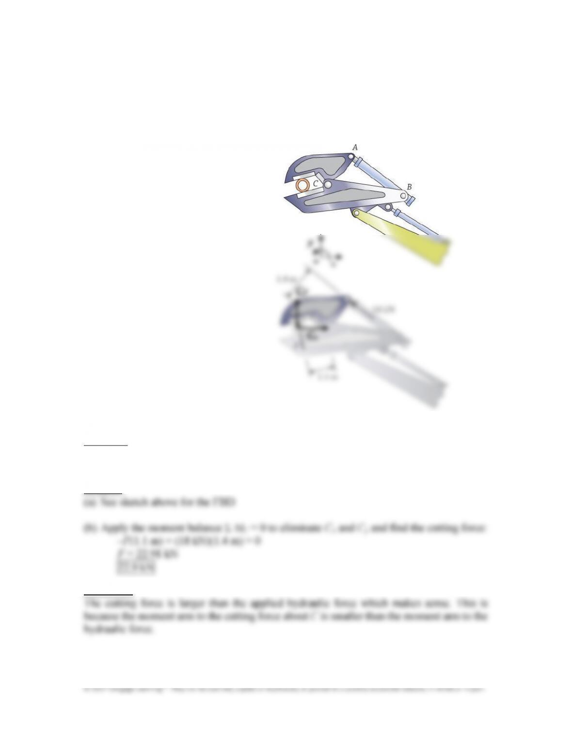
A cross section of the original design for the double&decker skyways in the Kansas
City Hyatt Regency hotel is shown, along with the forces acting on the nuts and
washers that support the upper and lower walkways. (a) Draw free body diagrams of
the upper and lower walkways, including the weight w that acts on each. (b) Determine
the forces P
1
and P
2
between the washers and the walkways, and the tensions T
1
and T
2
in the hanger rod.
Approach: Use the given information for the tensions T
1
and T
2
, and the forces between the
washers and walkways. The forces P
1
and P
2
act upward on the walkways.
Solution:
Chapter 4: Forces in Structures and Machines
89
© 2017 Cengage Learning
®
. May not be scanned, copied or duplicated, or posted to a publicly accessible website, in whole or in part.
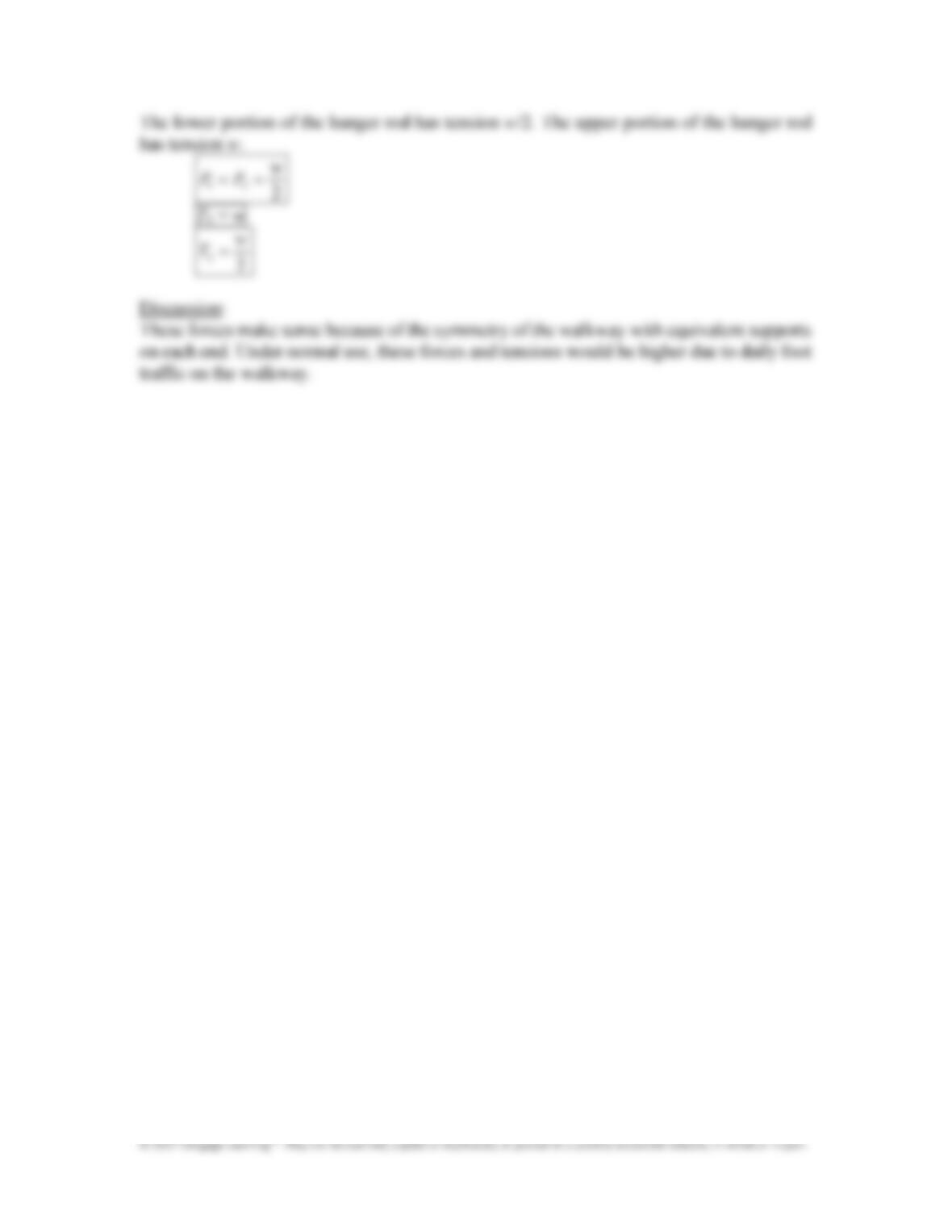
The lower portion of the hanger rod has tension w/2. The upper portion of the hanger rod
has tension w.
1 2
2
w
P P
= =
T
1
= w
2
2
w
T
=
Discussion:
These forces make sense because of the symmetry of the walkway with equivalent supports
on each end. Under normal use, these forces and tensions would be higher due to daily foot
traffic on the walkway.
Chapter 4: Forces in Structures and Machines
90
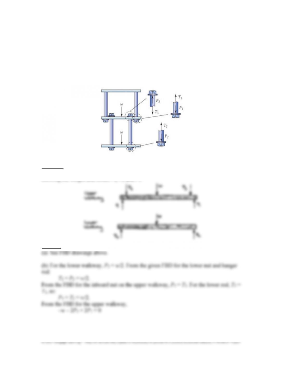
A cross§ional view is shown of the skyways in the Kansas City Hyatt Regency
hotel in their as&constructed form, along with the forces acting on the nuts and washers
that contact the two walkways. (a) Draw free body diagrams of the upper and lower
walkways, including the weight w that acts on each. (b) Determine the forces P
1
, P
2
,
and P
3
between the washers and the walkways, and the tensions T
1
, T
2
, and T
3
in the
hanger rods. (c) The skyways’ collapse was associated with an excessive force P
1
. How
does the value you calculated here compare with the value of P
1
obtained in P4.24?
Approach:
Use the FBDs of the nuts that support the two walkways. Draw FBDs of the walkways,
showing the weight and forces P
1
, P
2
and P
3
.
Solution:
Chapter 4: Forces in Structures and Machines
91
© 2017 Cengage Learning
®
. May not be scanned, copied or duplicated, or posted to a publicly accessible website, in whole or in part.
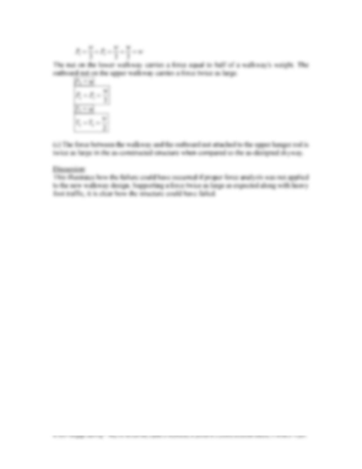
1 3
2 2 2
w w w
P P w
= + = + =
The nut on the lower walkway carries a force equal to half of a walkway’s weight. The
outboard nut on the upper walkway carries a force twice as large.
P
1
= w
2 3
2
w
P P
= =
T
1
= w
2 3
2
w
T T
= =
(c) The force between the walkway and the outboard nut attached to the upper hanger rod is
twice as large in the as&constructed structure when compared to the as&designed skyway.
Discussion:
This illustrates how the failure could have occurred if proper force analysis was not applied
to the new walkway design. Supporting a force twice as large as expected along with heavy
foot traffic, it is clear how the structure could have failed.