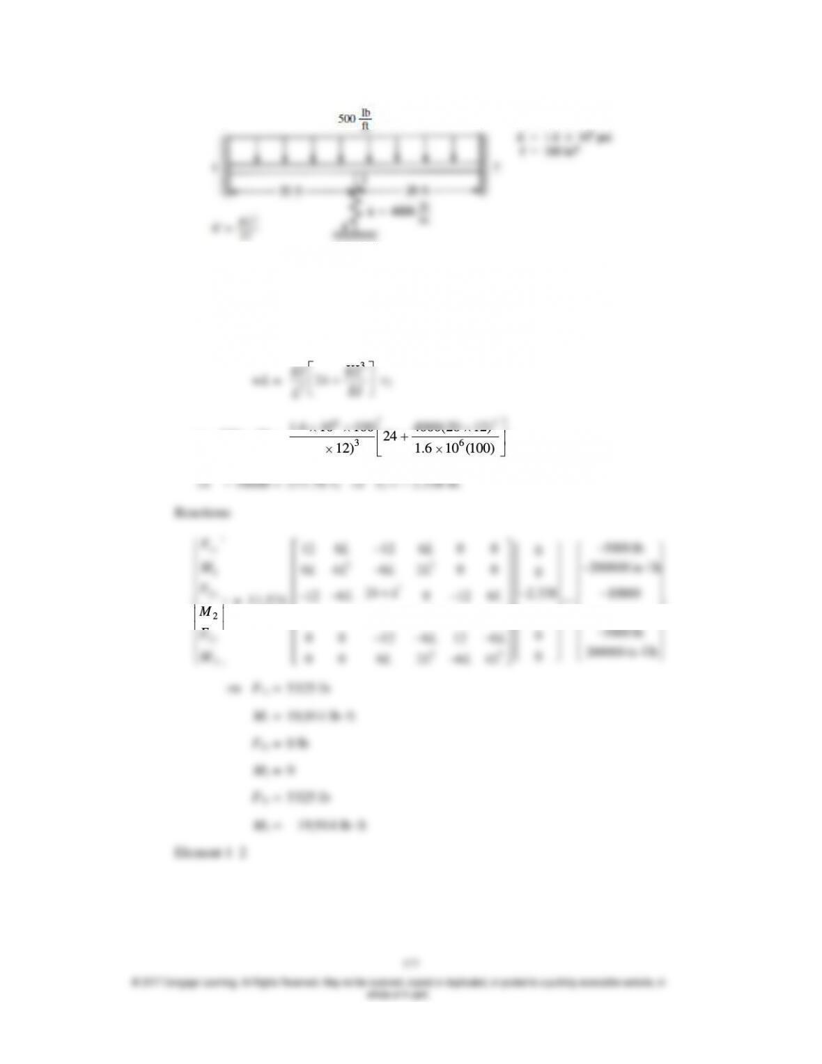
After applying the boundary conditions on {F} = [K] {d} we have
v1 =
1 = v3 =
3 =
2 = 0
So
3
324
EI KL
EI
L
– 500 20 =
63
36
1.6 10 100 4000(20 12)
24
(20 12) 1.6 10 (100)
v2
1
1
2
2
3
3
y
y
y
F
M
F
M
F
M
= 11.574
22
2
22
22
5000 lb
6 6 0 0
12 12 0
200000 in
6 6 0 0
42 0
24 2.338 10000
6 0 6
12 12
00
6 0 8 6
22
5000 lb
0
0 0 6 6
12 12
200000 in
0
0 0 6 6
24
LL
LL
LL
k
LL
L L L
LL
LL
LL
LL
lb
lb
1
1
2
2
y
y
f
m
f
m
= 11.574
22
22
6 6 0 5000
12 12
6 6 0 200000
42 –
6 6 2.338 5000
12 12
6 6 0 200000
24
LL
LL
LL
LL
LL
LL
4.26
v1 = 0 = v2 = v3
42
551
242
55
[k2–3] = EI
3
2
42
44
24
44
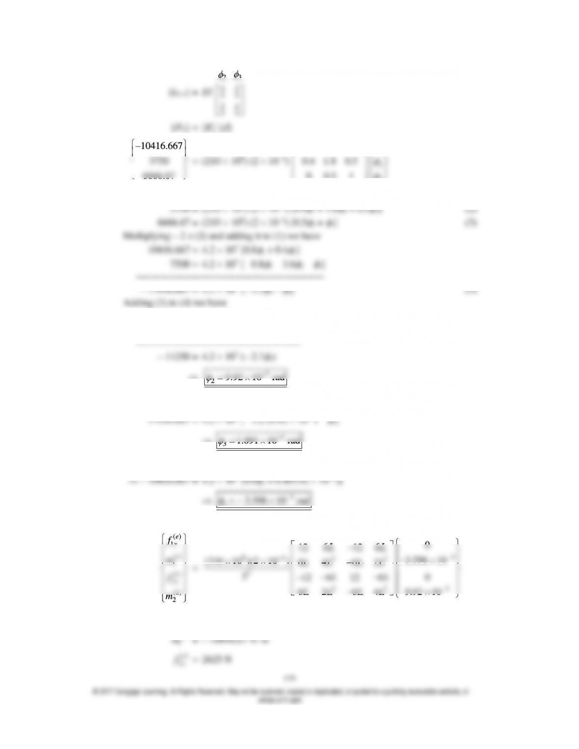
{F0} = [K]{d}
10416.667
6666.67
1
2
3
0.8 0.4 0
0 0.5 1
– 10416.667 = (210 109) (2 10–4) [0.8
1 + 0.4
2) (1)
– 17916.667 = 4.2 107 [– 3.2
2 –
3]
6666.667 = 4.2 107 [0.5
2 +
3]
5
29.92 10 rad
Substituting into (4) we have
4
31.091 10 rad
Substituting in (1)
()
2
e
m
= – 2708.33 N m
1
1
2
2
y
y
f
m
f
m
=
2625 12500
10416.667 10416.667
2625 12500
2708.33 10416.667
()
2
()
2
()
3
()
3
e
y
e
e
y
e
f
m
f
m
=
94
3
(210 10 )(2 10 )
4
5
22
4
22
0
66
12 12
9.92 10
66
42
6 6 0
12 12
6 6 1.091 10
24
LL
LL
LL
LL
LL
LL
4.27
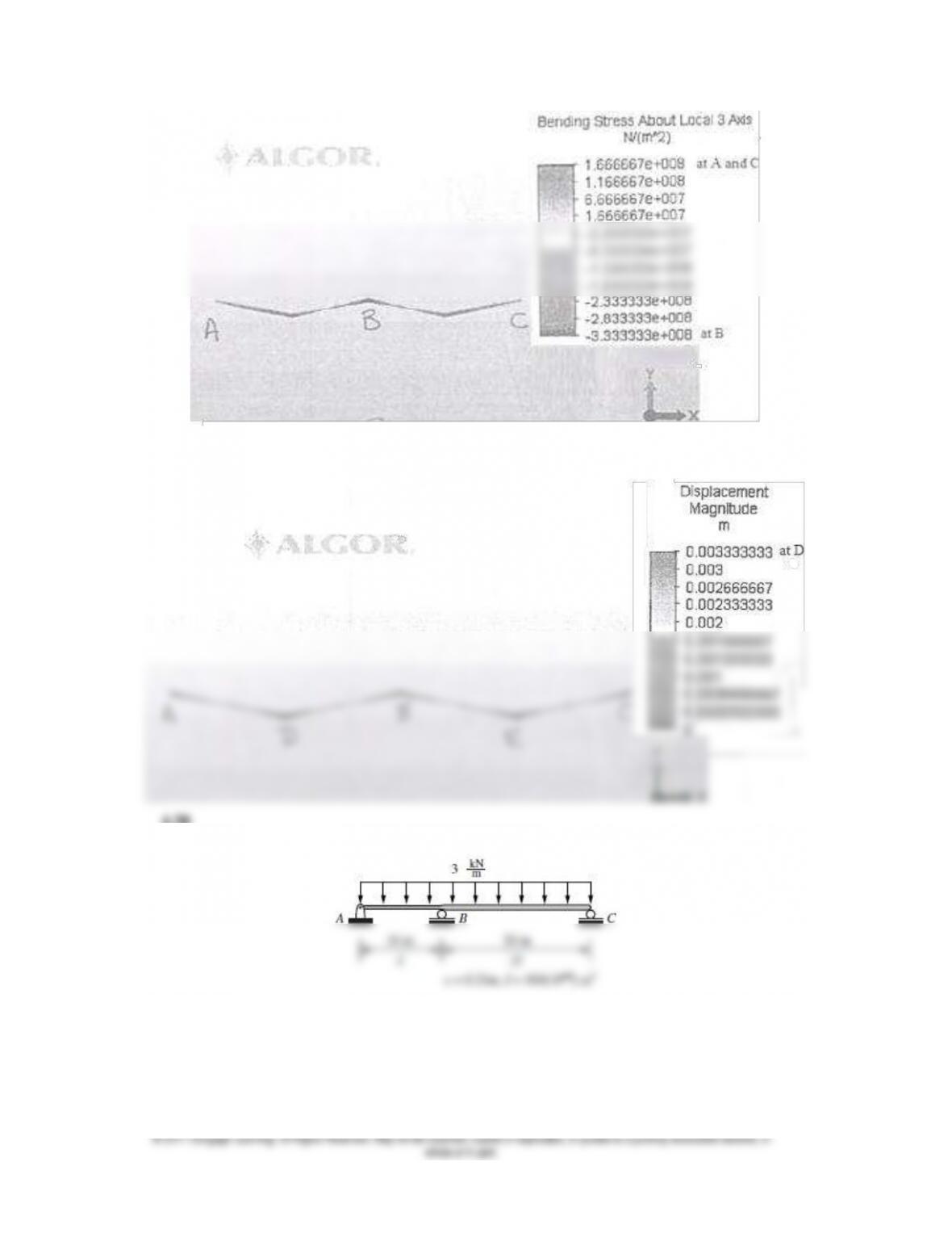
181
4.28
Figure P4–28
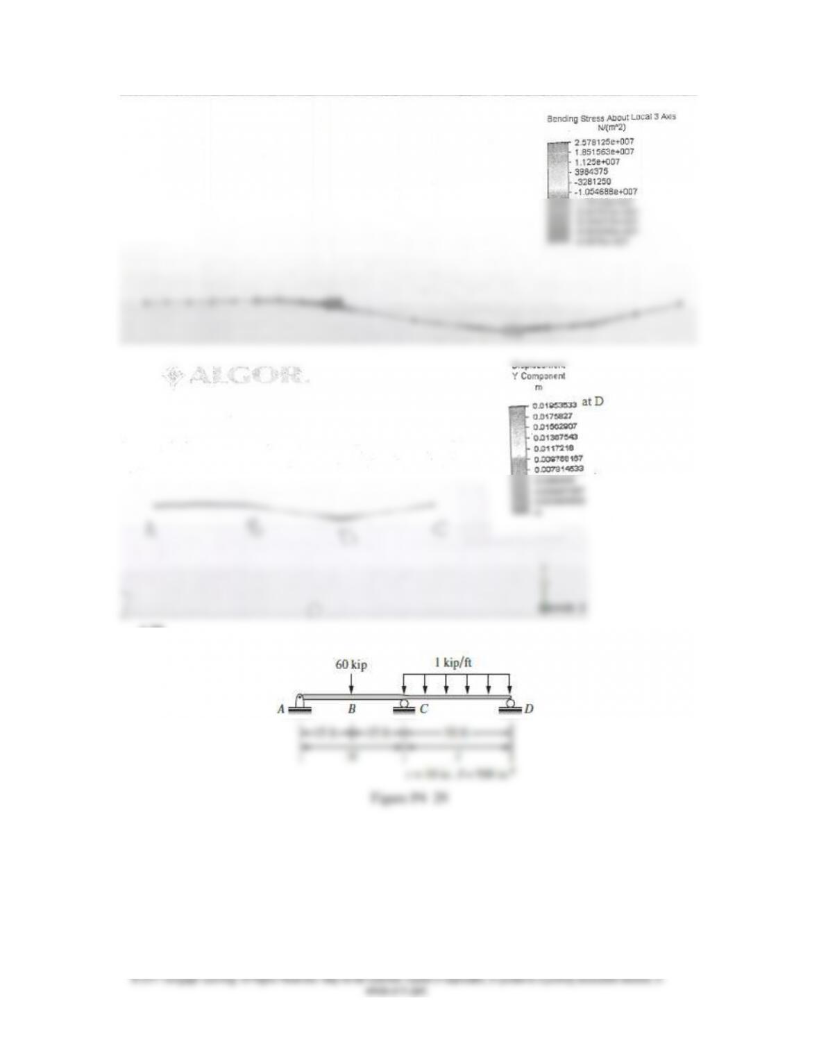
182
4.29
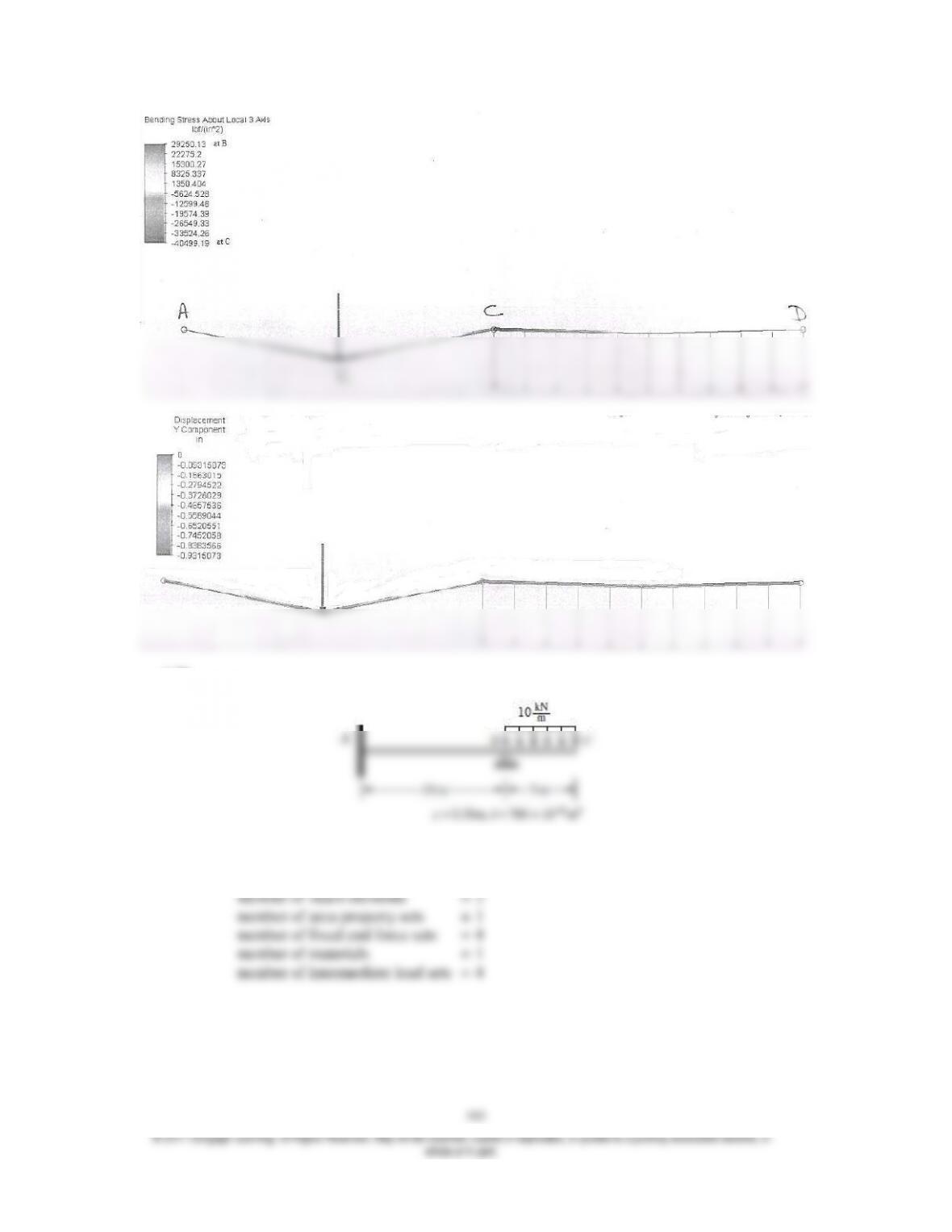
4.30
Figure P4–30
1 **** BEAM ELEMENTS
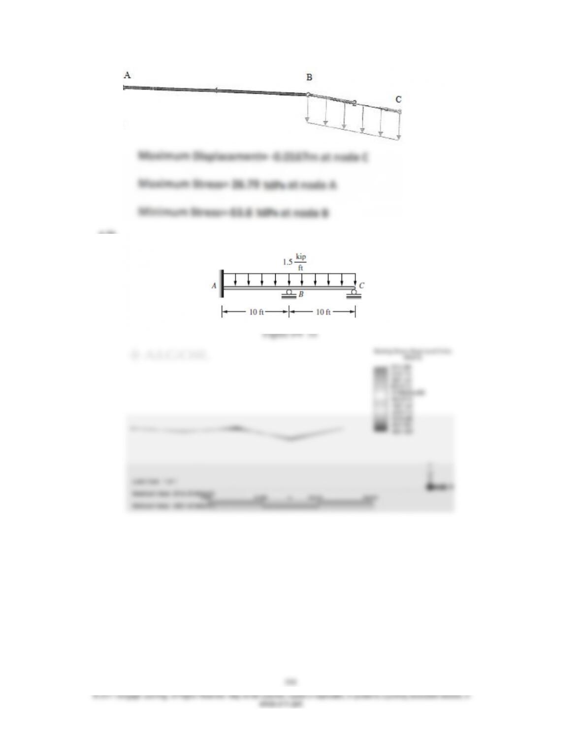
4.31
185
4.32
Figure P4–32
186
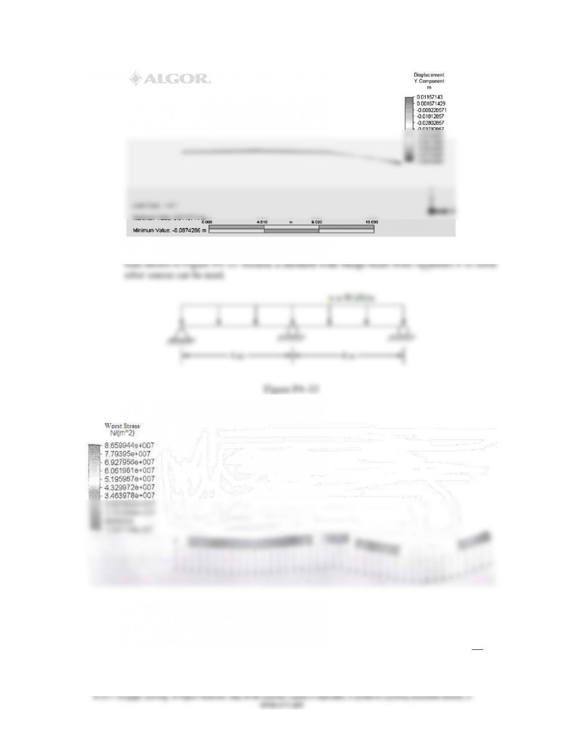
4.33 Design a beam of ASTM A36 steel with allowable bending stress of 160 MPa to support the
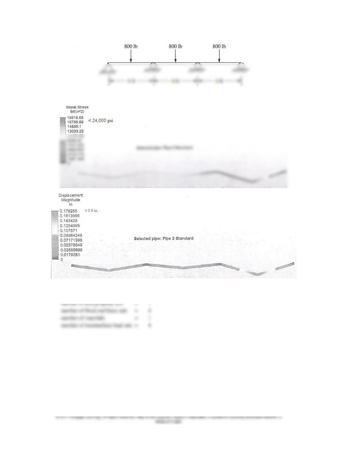
4.34 Select a standard steel pipe from Appendix F to support the load shown. The allowable
bending stress must not exceed 24 ksi, and the allowable deflection must not exceed
L
360
of
any span.
187
Figure P4–34
1 **** BEAM ELEMENTS
number of beam elements = 6
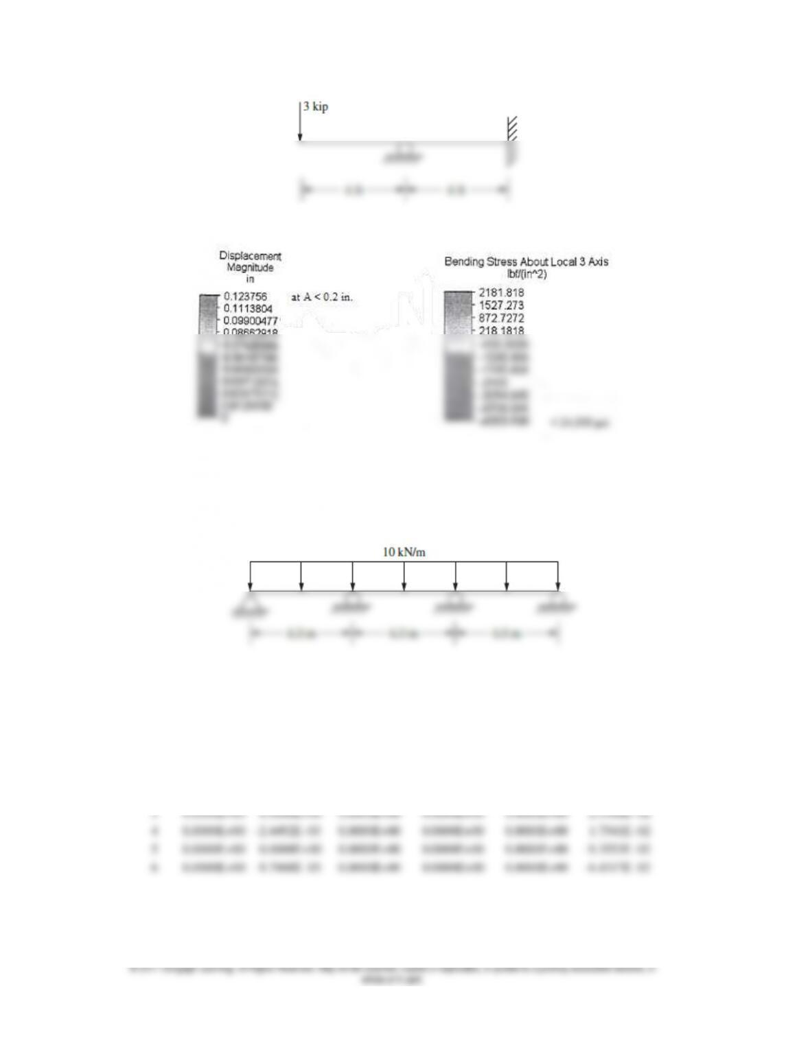
4.35 Select a rectangular structural tube from Appendix F to support the loads shown for the
beam in Figure P4–33. The allowable bending stress should not exceed 24 ksi and allowable
deflection ≤ 0.2 in. Answers for a 9” × 9” × ½ box section
188
Figure P4–35
4.36 Select a standard W section from Appendix F or some other source to support the loads
shown for the beam in Figure P4–34. The bending stress must not exceed 160 MPa.
Figure P4 –36
Displacements/Rotations (degrees) of nodes
NODE X– Y– Z– X– Y– Z–
number translation translation translation rotation rotation rotation
1 0.0000E+00 0.0000E+00 0.0000E+00 0.0000E+00 0.0000E+00 0.0000E+00
2 0.0000E+00 –4.2861E–03 0.0000E+00 0.0000E+00 0.0000E+00 –5.8470E–03
1 **** BEAM ELEMENT FORCE AND MOMENTS
ELEMENT CASE AXIAL SHEAR SHEAR TORSION BENDING BENDING
189
NO. (MODE) FORCE FORCE FORCE MOMENT MOMENT MOMENT
R1 R2 R3 M1 M2 M3
1 1 0.000E+00 –6.115E+04 0.000E+00 0.000E+00 0.000E+00 –6.231E+04
0.000E+00 –1.154E+03 0.000E+00 0.000E+00 0.000E+00 3.115E+04
2 1 0.000E+00 –1.154E+03 0.000E+00 0.000E+00 0.000E+00 3.115E+04
0.000E+00 5.885E+04 0.000E+00 0.000E+00 0.000E+00 –5.538E+04
3 1 0.000E+00 –5.654E+04 0.000E+00 0.000E+00 0.000E+00 –5.538E+04
1**** BEAM ELEMENT STRESSES
ELEMENT CASE P/A P/A + M2/S2 P/A–M2/S2 P/A+M3/S3 P/A-M3/S3 WORST SUM
NO. (MODE)
1 1 0.000E+00 0.000E+00 0.000E+00 –1.139E+08 1.139E+08 1.139E+08
0.000E+00 0.000E+00 0.000E+00 5.695E+07 – 5.695E+07 5.695E+07
2 1 0.000E+00 0.000E+00 0.000E+00 5.695E+07 – 5.569E+07 5.695E+07
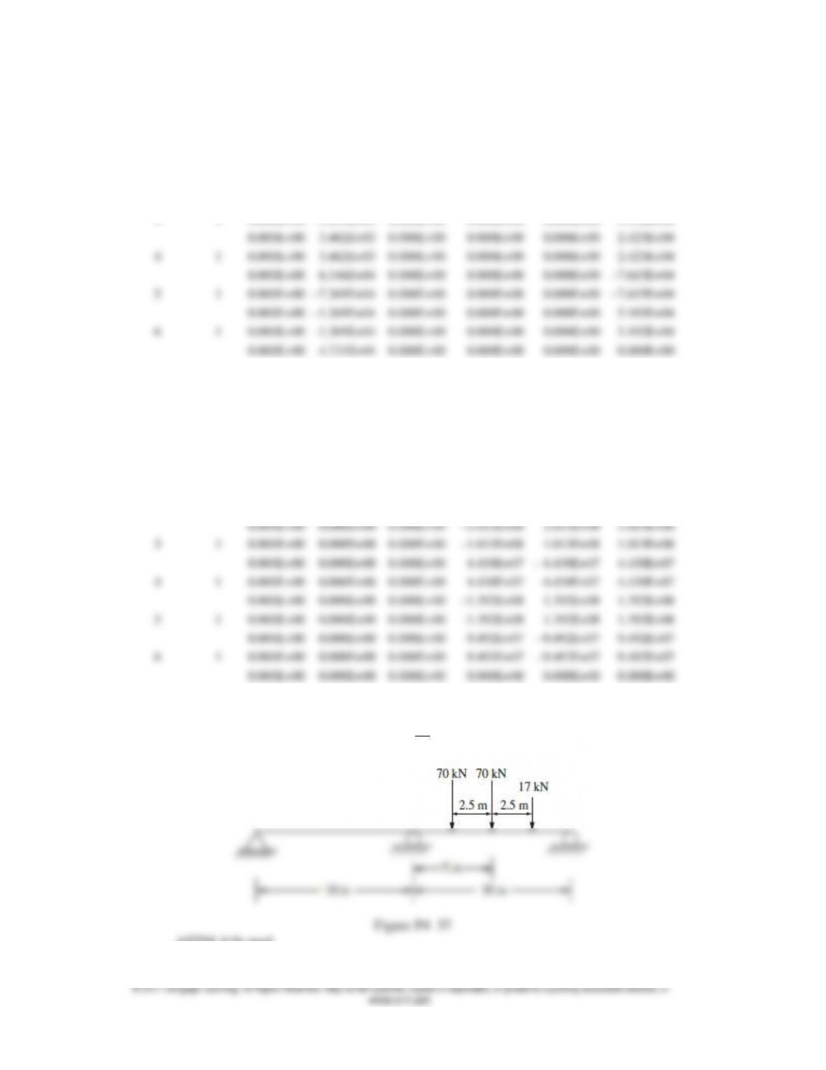
4.37 For the beam shown in Figure P4–37, determine a suitable sized W section from Appendix F
or from another suitable source such that the bending stress does not exceed 150 MPa and
the maximum deflection does not exceed
L
360
of any span.
ASTM A36 steel