730
16–97.
SOLUTION
5
0.1–x
=
0.75
x
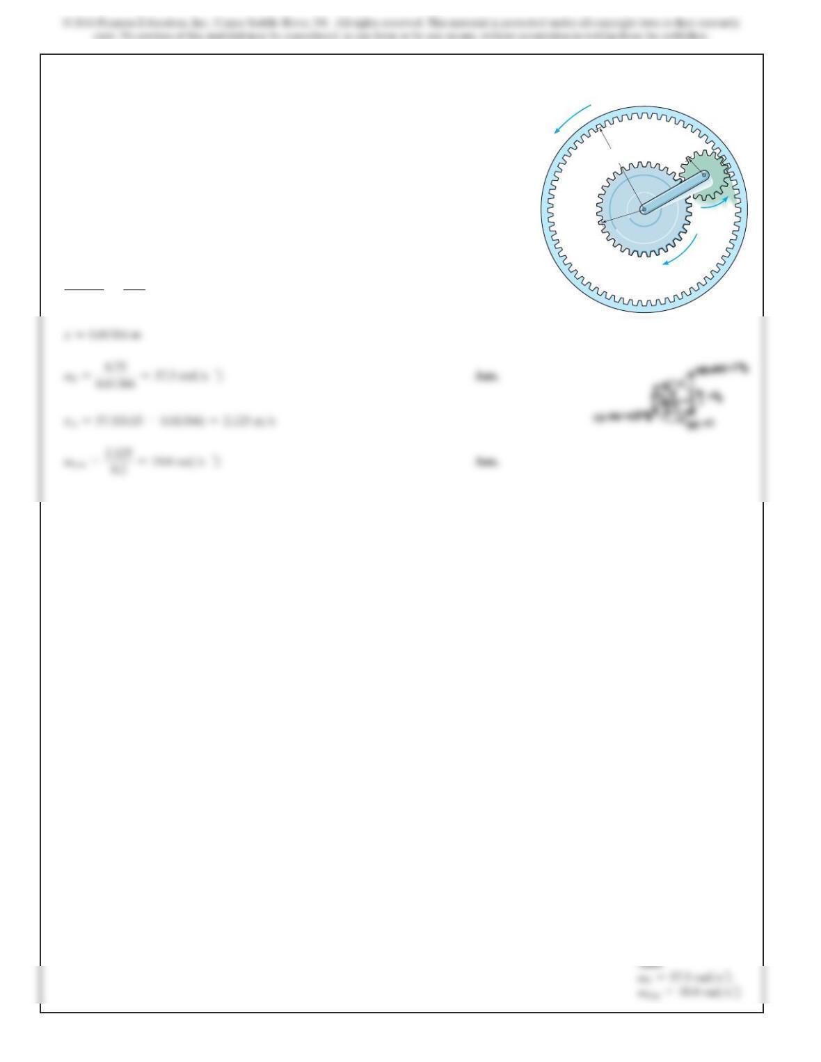
If the hub gear
H
and ring gear
R
have angular velocities
vH=5 rad>s and vR=20 rad>s, respectively, determine
the angular velocity vS of the spur gear S and the angular
velocity of its attached arm OA.
H
ω
S
ω
R
ω
O
150 mm
50 mm
A
S
H
R
250 mm
731
16–98.
SOLUTION
The IC is at A.
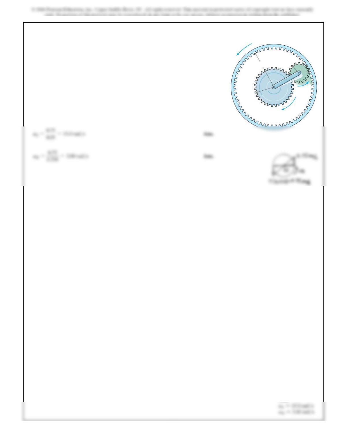
If the hub gear H has an angular velocity vH= 5 rad
>
s,
determine the angular velocity of the ring gear R so that
the arm OA attached to the spur gear S remains stationary
(vOA =0). What is the angular velocity of the spur gear?
H
ω
S
ω
R
ω
O
150 mm
50 mm
A
S
H
R
250 mm
Ans:
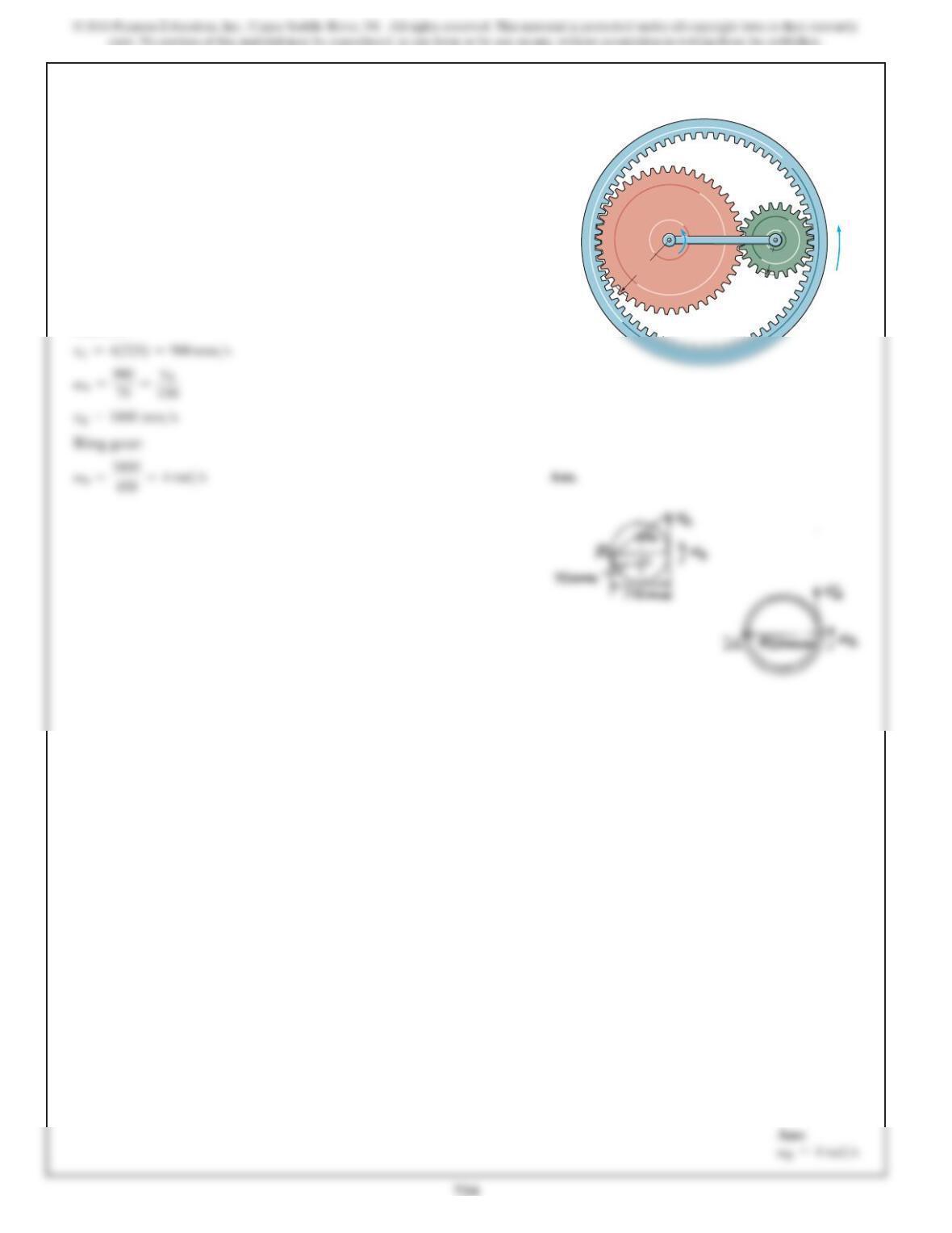
16–99.
SOLUTION
rB>IC =0.3
sin 30° =0.6 m
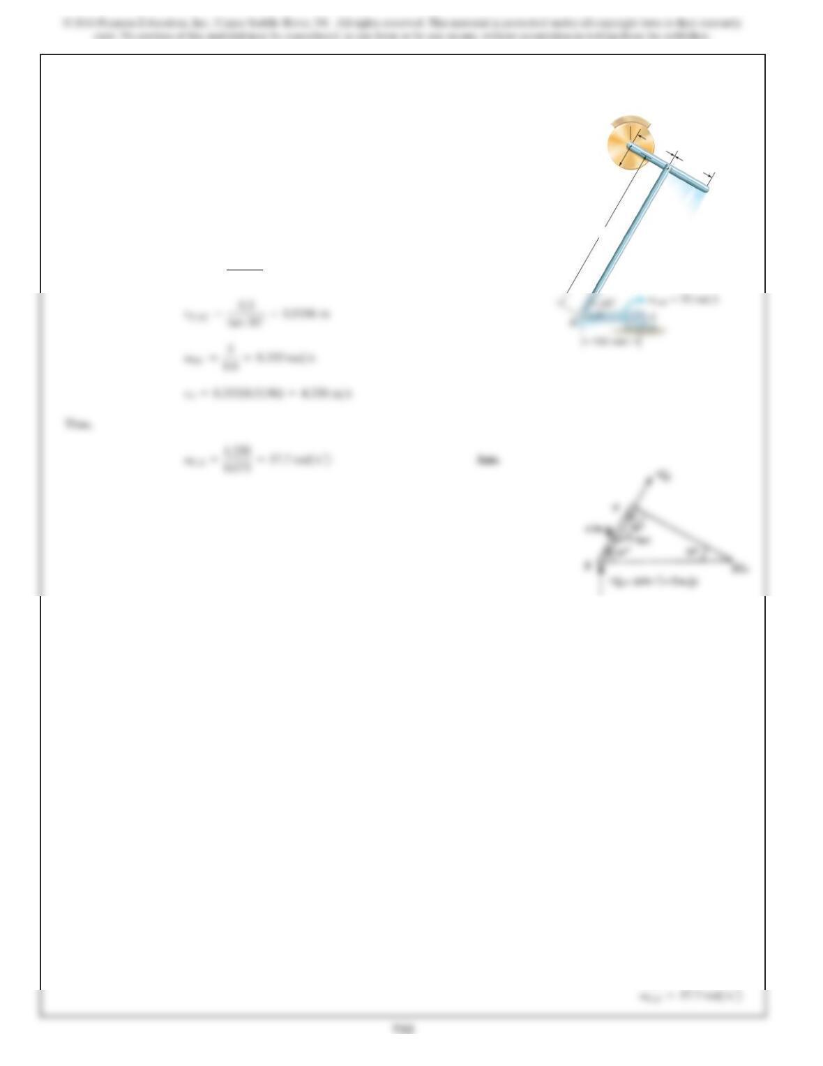
The crankshaft AB rotates at about the
fixed axis through point A, and the disk at Cis held fixed in
its support at E. Determine the angular velocity of rod CD
at the instant shown.
vAB =50 rad
>
s
E
C
D
F
75 mm
40 mm 75 mm
300 mm
Ans:
733
*16–100.
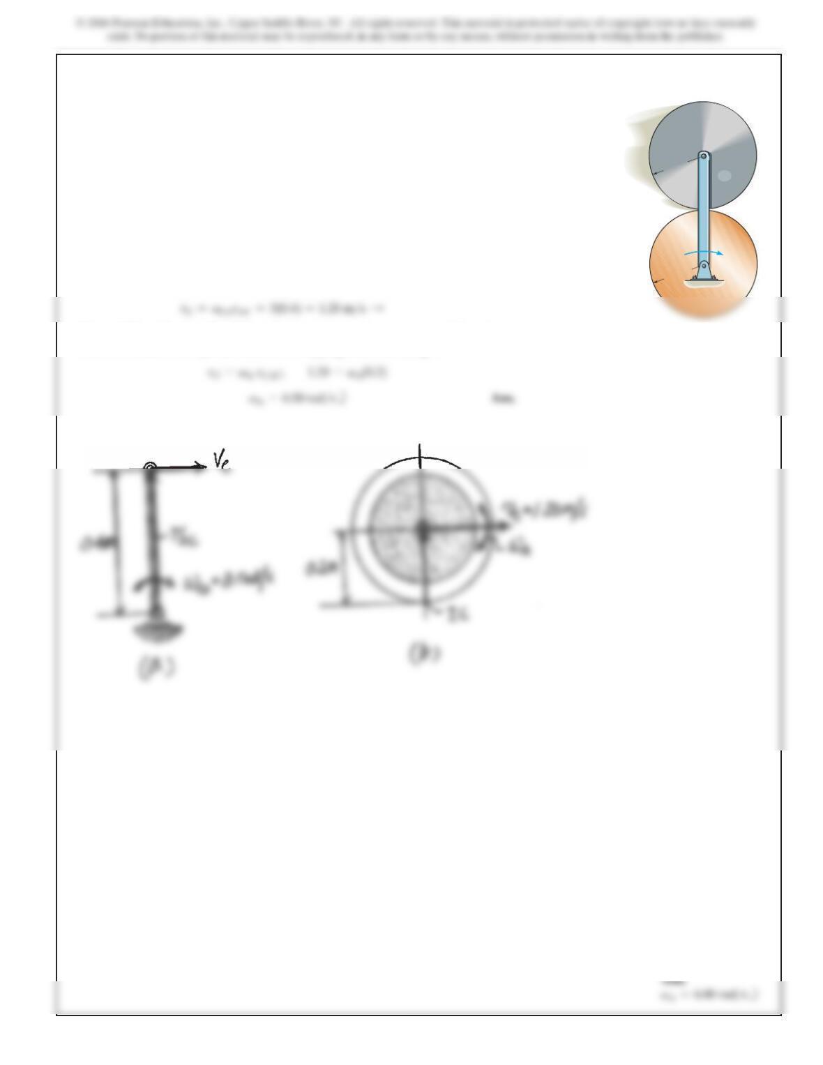
Cylinder A rolls on the fixed cylinder B without slipping. If
bar CD is rotating with an angular velocity of
v
CD
=
3 rad
>
s, determine the angular velocity of A.
SOLUTION
Rotation About A Fixed Axis. The magnitude of the velocity of C is
General Plane Motion. The IC for cylinder A is located at the bottom of the cylinder
where it contacts with cylinder B, since no slipping occurs here, Fig. b.
C
D
B
A
200 mm
200 mm
vCD
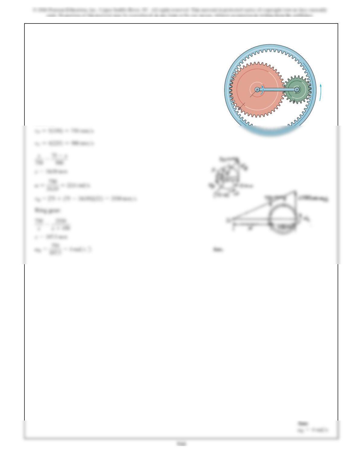
16–101.
The planet gear A is pin connected to the end of the link
BC. If the link rotates about the fixed point B at
4 rad
>
s, determine the angular velocity of the ring gear R.
The sun gear D is fixed from rotating.
SOLUTION
Gear A:
R
D
BC
A
150 mm 75 mm
v
R
vBC 4 rad/s
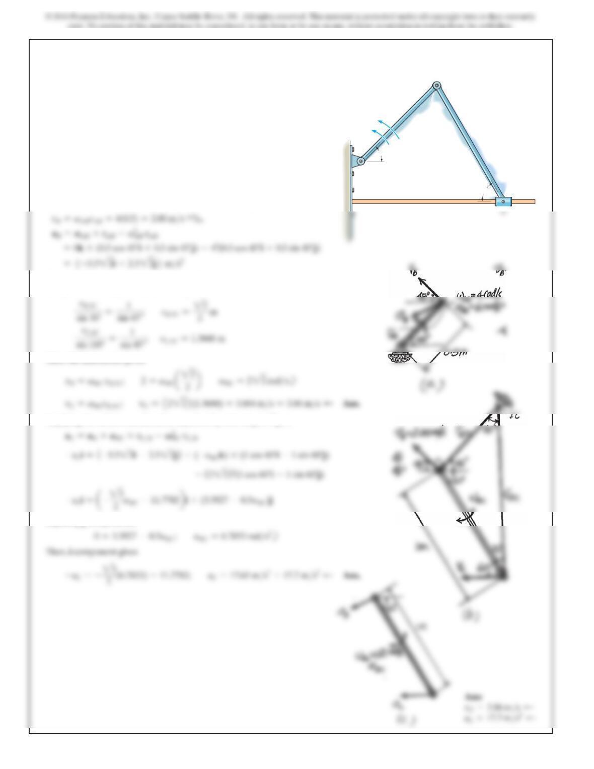
16–102.
Solve Prob. 16–101 if the sun gear D is rotating clockwise
atvD
=5 rad>s
while link BC rotates counterclockwise at
vBC
=4 rad>s
.
R
D
BC
A
150 mm 75 mm
vR
vBC 4 rad/s
SOLUTION
Gear A:
736
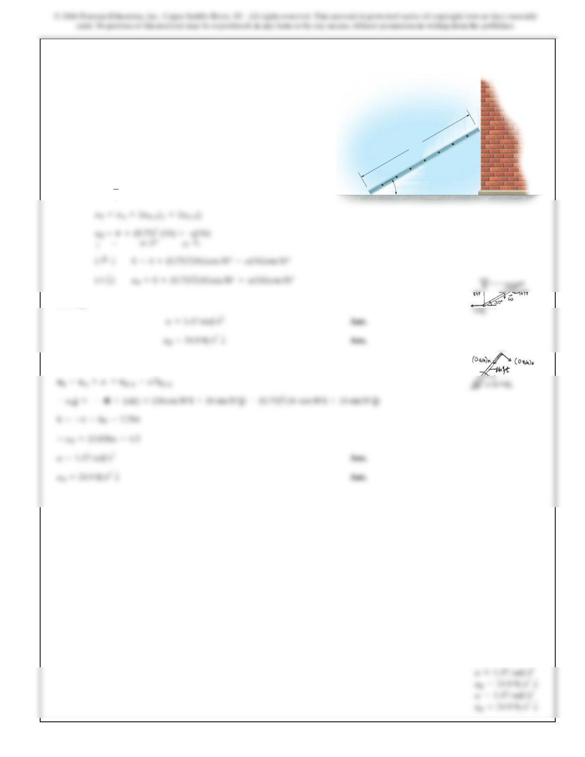
16–103.
Bar AB has the angular motions shown. Determine the
velocity and acceleration of the slider block C at this instant.
SOLUTION
Rotation About A Fixed Axis. For link AB, refer to Fig. a.
General Plane Motion. The IC of link BC can be located using vB and vC as shown
in Fig. b. From the geometry of this figure,
Then the kinematics gives,
Applying the relative acceleration equation by referring to Fig. c,
Equating j components,
1 m
0.5 m
B
A
45
60
vAB fi 4 rad/s
AB fi 6 rad/s2
a
737
Ans:
*16–104.
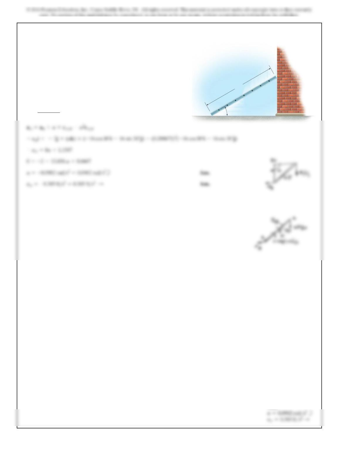
At a given instant the bottom Aof the ladder has an
acceleration
and velocity both
acting
to the left. Determine the acceleration of the top of
the
ladder, B, and the ladder’s angular acceleration at this
same instant.
vA=6ft>s,aA=4ft>s2
30
A
B
16 ft
SOLUTION
Solving,
Also:
v=6
8=0.75 rad>s
738
16–105.
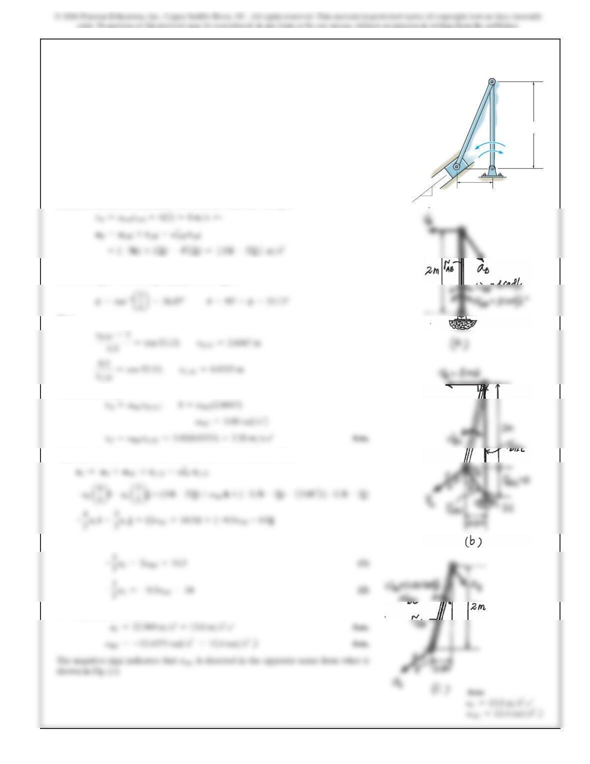
At a given instant the top Bof the ladder has an
acceleration and a velocity of both
acting downward. Determine the acceleration of the
bottom Aof the ladder, and the ladder’s angular
acceleration at this instant.
vB=4ft>s,aB=2ft>s2
SOLUTION
v=4
16 cos 30° =0.288675 rad>s
30
A
B
16 ft
Ans:
739
16–106.
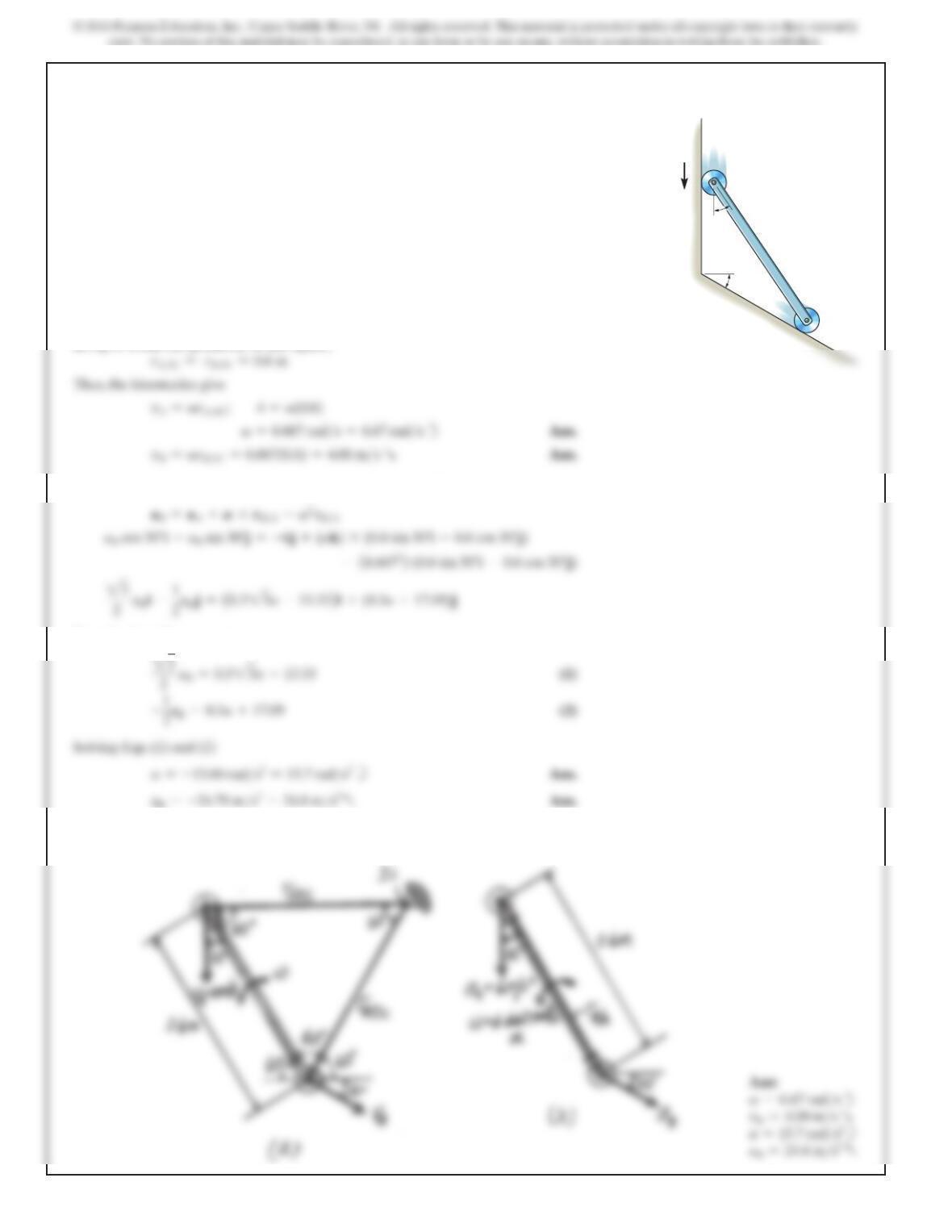
Member AB has the angular motions shown. Determine the
velocity and acceleration of the slider block C at this instant.
2 m
0.5 m
4 rad/s
5 rad/s2
A
C
B
5
3
4
SOLUTION
Rotation About A Fixed Axis. For member AB, refer to Fig. a.
General Plane Motion. The IC for member BC can be located using vB and vC as
shown in Fig. b. From the geometry of this figure
Then
The kinematics gives
Applying the relative acceleration equation by referring to Fig. c,
Equating i and j components
Solving Eqs. (1) and (2),
740
16–107.
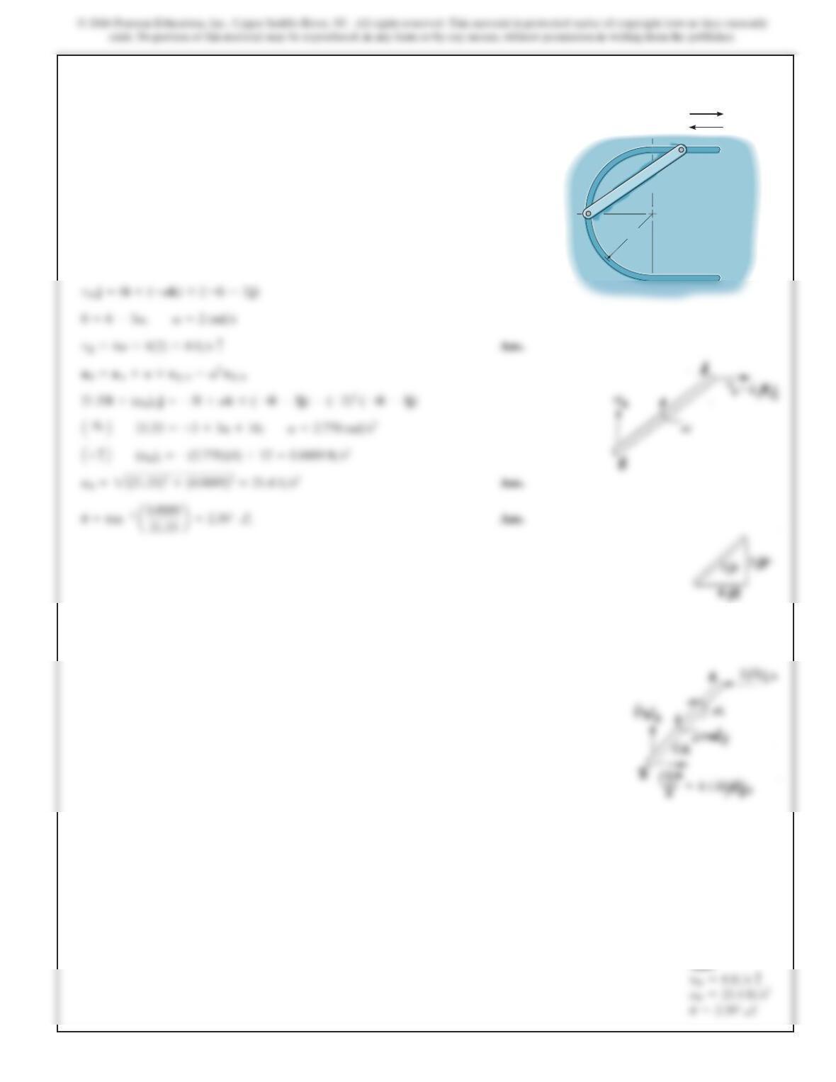
At a given instant the roller A on the bar has the velocity
and acceleration shown. Determine the velocity and
acceleration of the roller B, and the bar’s angular velocity
and angular acceleration at this instant.
SOLUTION
General Plane Motion. The IC of the bar can be located using
vA
and
vB
as shown
in Fig. a. From the geometry of this figure,
Applying the relative acceleration equation, by referring to Fig. b,
Equating i and j components,
B=–
The negative signs indicate that
A
and
aB
are directed in the senses that opposite to
those shown in Fig. b
A
B
0.6 m
30
30
4 m/s
6 m/s2
741
Ans:
*16–108.
SOLUTION
vB=vA+v*rB>A
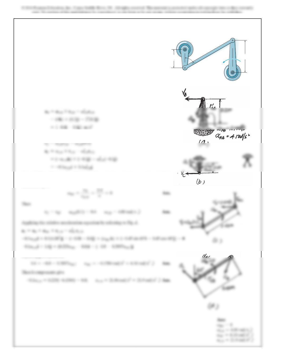
The rod is confined to move along the path due to the pins
at its ends. At the instant shown, point Ahas the motion
shown. Determine the velocity and acceleration of point B
at this instant.
3ft
5 ft
A
B
v
A
=6ft/s
a
A
=3ft/s
2
742
16–109.
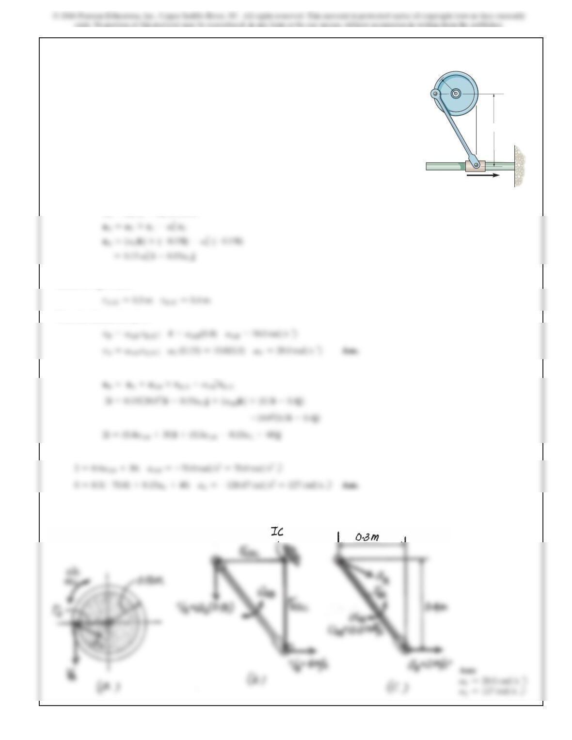
Member AB has the angular motions shown. Determine the
angular velocity and angular acceleration of members CB
and DC.
vAB 2 rad/s
aAB 4 rad/s2
200 mm
450 mm
60fi
100 mm
B
A
D
C
SOLUTION
Rotation About A Fixed Axis. For crank AB, refer to Fig. a.
vB=
v
ABrAB =2(0.2) =0.4 m>s d
For link CD, refer to Fig. b.
General Plane Motion. The IC of link CD can be located using
vB
and
vC
of which
in this case is at infinity as indicated in Fig. c. Thus,
r
B
>
IC
=r
C
>
IC
=∞
. Thus,
kinematics gives
Equating j components,
743
16–110.
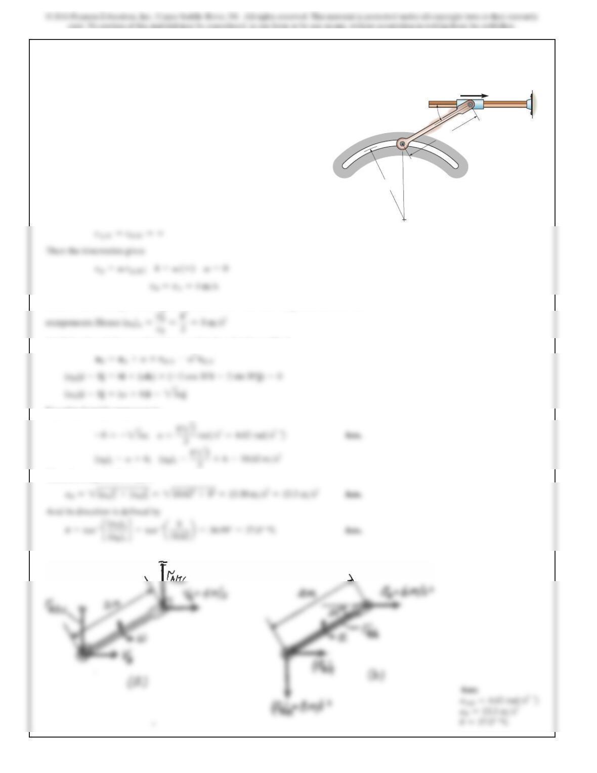
The slider block has the motion shown. Determine the
angular velocity and angular acceleration of the wheel at
this instant.
SOLUTION
Rotation About A Fixed Axis. For wheel C, refer to Fig. a.
v
v
r
v
(0.15)
T
General Plane Motion. The IC for crank AB can be located using
vA
and
vB
as
shown in Fig. b. Here
Then the kinematics gives
Applying the relative acceleration equation by referring to Fig. c,
Equating i and j components,
The negative signs indicate that
AC
and
AAB
are directed in the sense that those
shown in Fig. a and c.
400 mm
A
C
B
150 mm
vB 4 m/s
aB 2 m/s2
744
16–111.
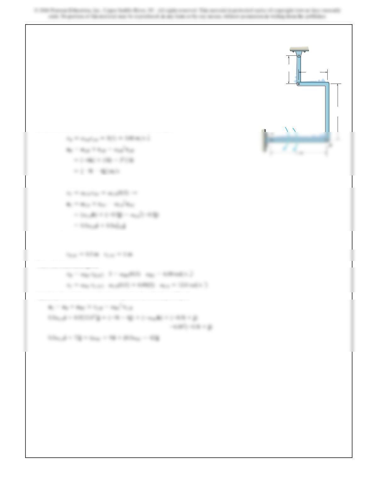
At a given instant the slider block A is moving to the right
with the motion shown. Determine the angular acceleration
of link AB and the acceleration of point B at this instant.
2 m
2 m
30A
B
vA fi
4 m
/
s
aA fi 6 m/s2
SOLUTION
General Plane Motion. The IC of the link can be located using
vA
and
vB
, which in
this case is at infinity as shown in Fig. a. Thus
Since B moves along a circular path, its acceleration will have tangential and normal
Applying the relative acceleration equation by referring to Fig. b,
Equating i and j componenets,
Thus, the magnitude of
aB
is
745
*16–112.
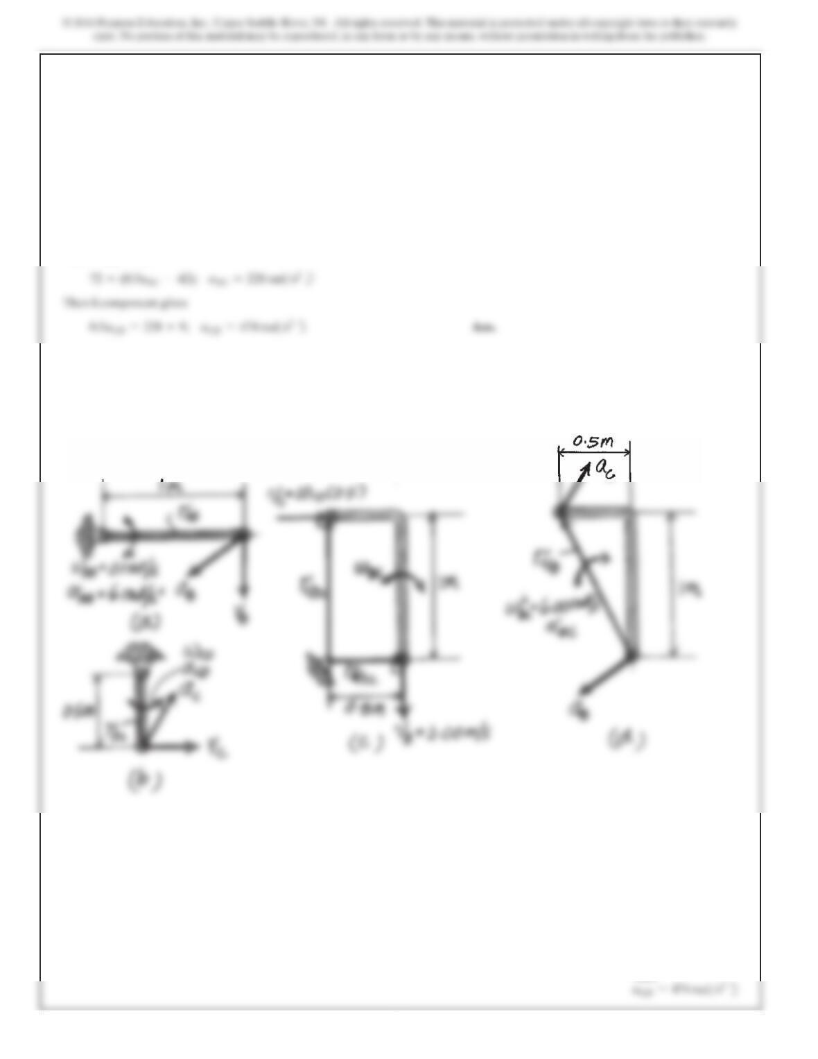
Determine the angular acceleration of link CD if link AB
has the angular velocity and angular acceleration shown.
SOLUTION
Rotation About A Fixed Axis. For link AB, refer to Fig. a.
For link CD, refer to Fig. b
General Plane Motion. The IC of link BC can be located using
vA
and
vB
as shown
in Fig. c. Thus
Then, the kinematics gives
Applying the relative acceleration equation by referring to Fig. d,
0.5 m
0.5 m
1 m
C
D
aAB 6 rad/s2
vAB 3 rad/s
746
*16–112. Continued
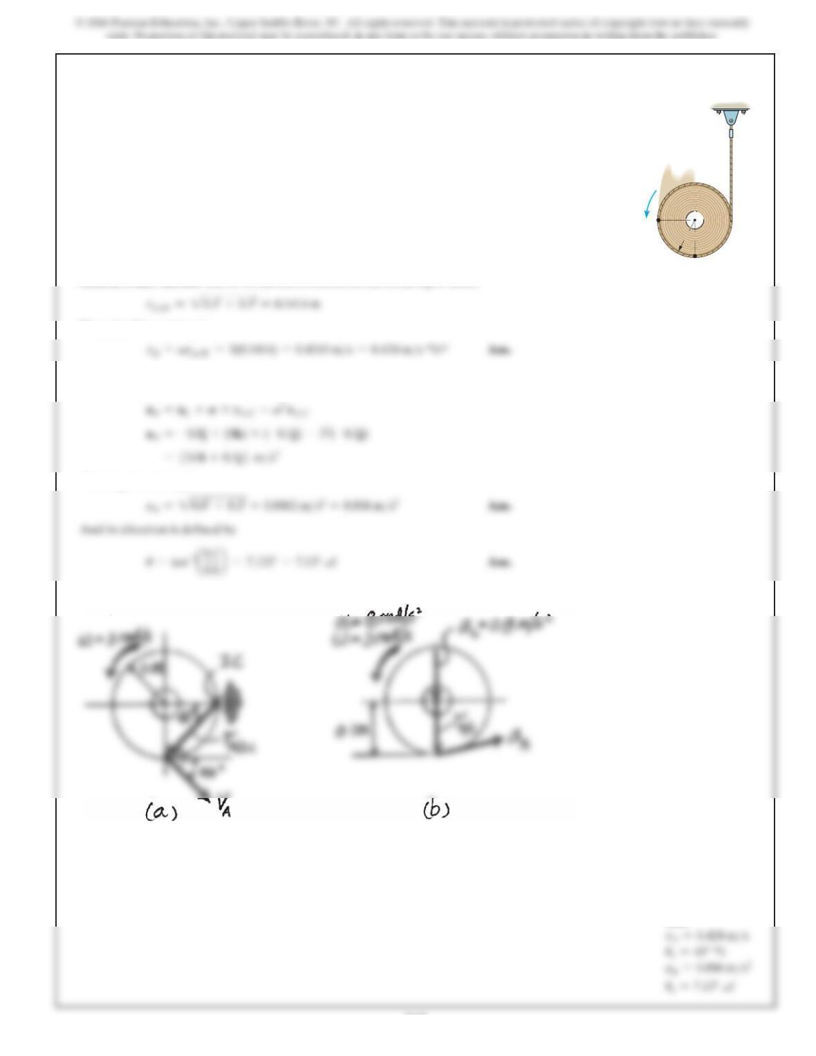
Equating j components,
Ans:
747
16–113.
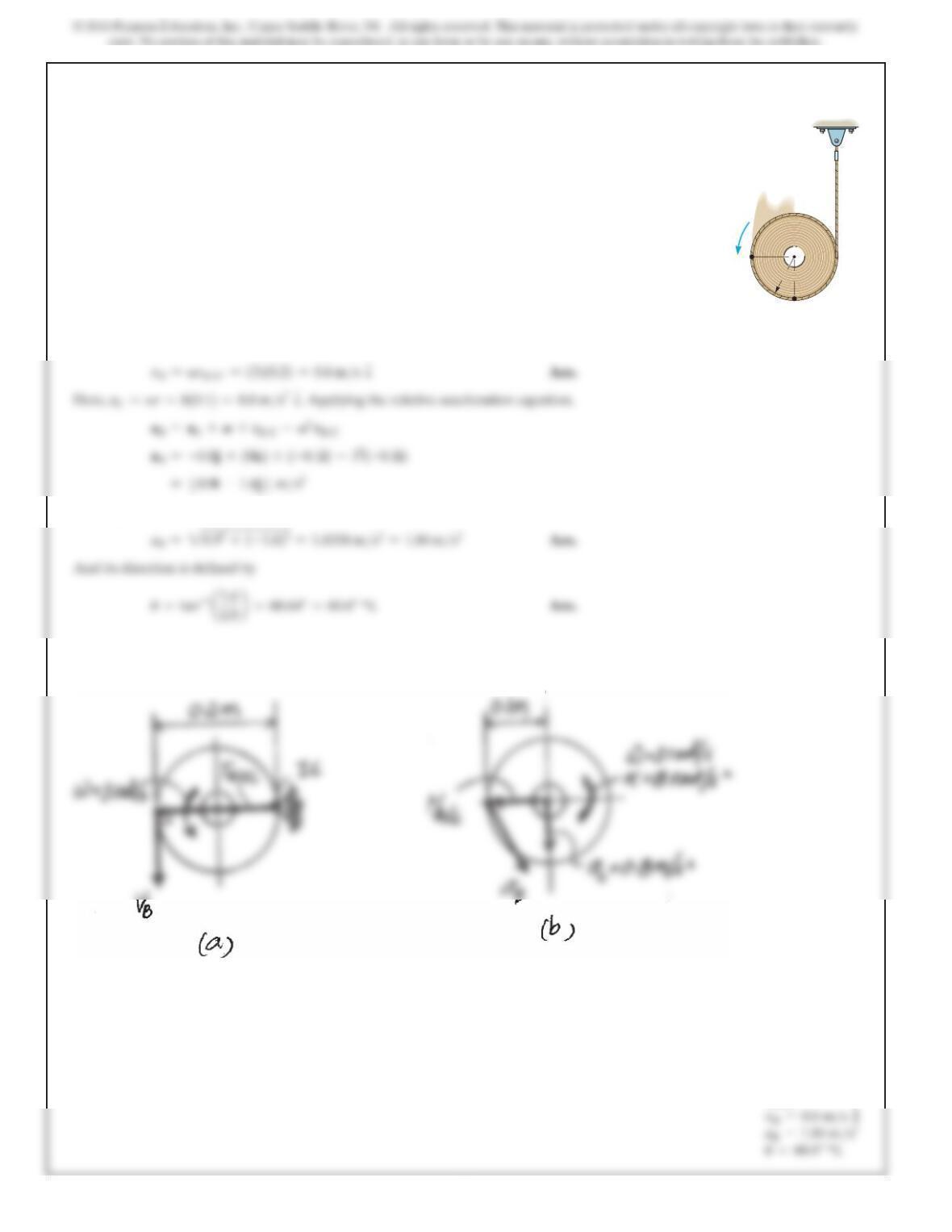
The reel of rope has the angular motion shown. Determine
the velocity and acceleration of point A at the instant shown.
Ans:
A
B
100 mm
C
3 rad/s
8 rad/s2
v
a
SOLUTION
General Plane Motion. The IC of the reel is located as shown in Fig. a. Here,
Then, the Kinematics give
Here a
C=
ar
=
8(0.1)
=
0.8 m
>
s
2
T
. Applying the relative acceleration equation
by referring to Fig. b,
The magnitude of
aA
is
748
16–114.
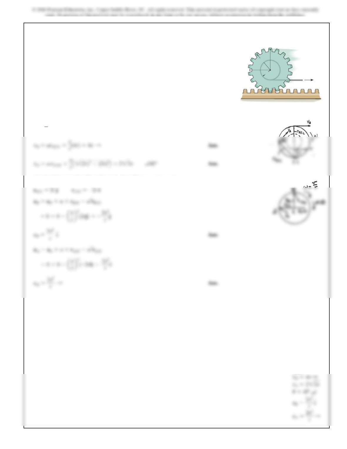
The reel of rope has the angular motion shown. Determine
the velocity and acceleration of point B at the instant shown.
Ans:
SOLUTION
General Plane Motion. The IC of the reel is located as shown in Fig. a. Here,
r
B
>
FC
=0.2 m
. Then the kinematics gives
The magnitude of
aB
is
A
B
100 mm
C
3 rad/s
8 rad/s2
v
a
749
16–115.
G
B
r
2r
v
A
A cord is wrapped around the inner spool of the gear. If it is
pulled with a constant velocity v, determine the velocities
and accelerations of points Aand B.The gear rolls on the
fixed gear rack.
SOLUTION
Velocity analysis:
Acceleration equation: From Example 16–3, Since aG = 0,
a=0
v=v
r
Ans: