670
16–41.
SOLUTION
#
y=0.3 cos u
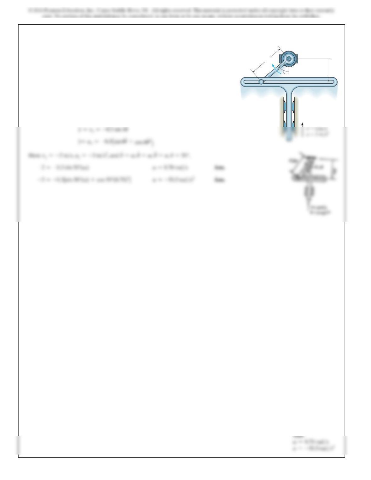
At the instant the slotted guide is moving upward
with an acceleration of and a velocity of .
Determine the angular acceleration and angular velocity of
link AB at this instant. Note: The upward motion of the
guide is in the negative ydirection.
2m>s3m>s2
u
=50°,
300 mm
y
A
B
V,A
U
671
16–42.
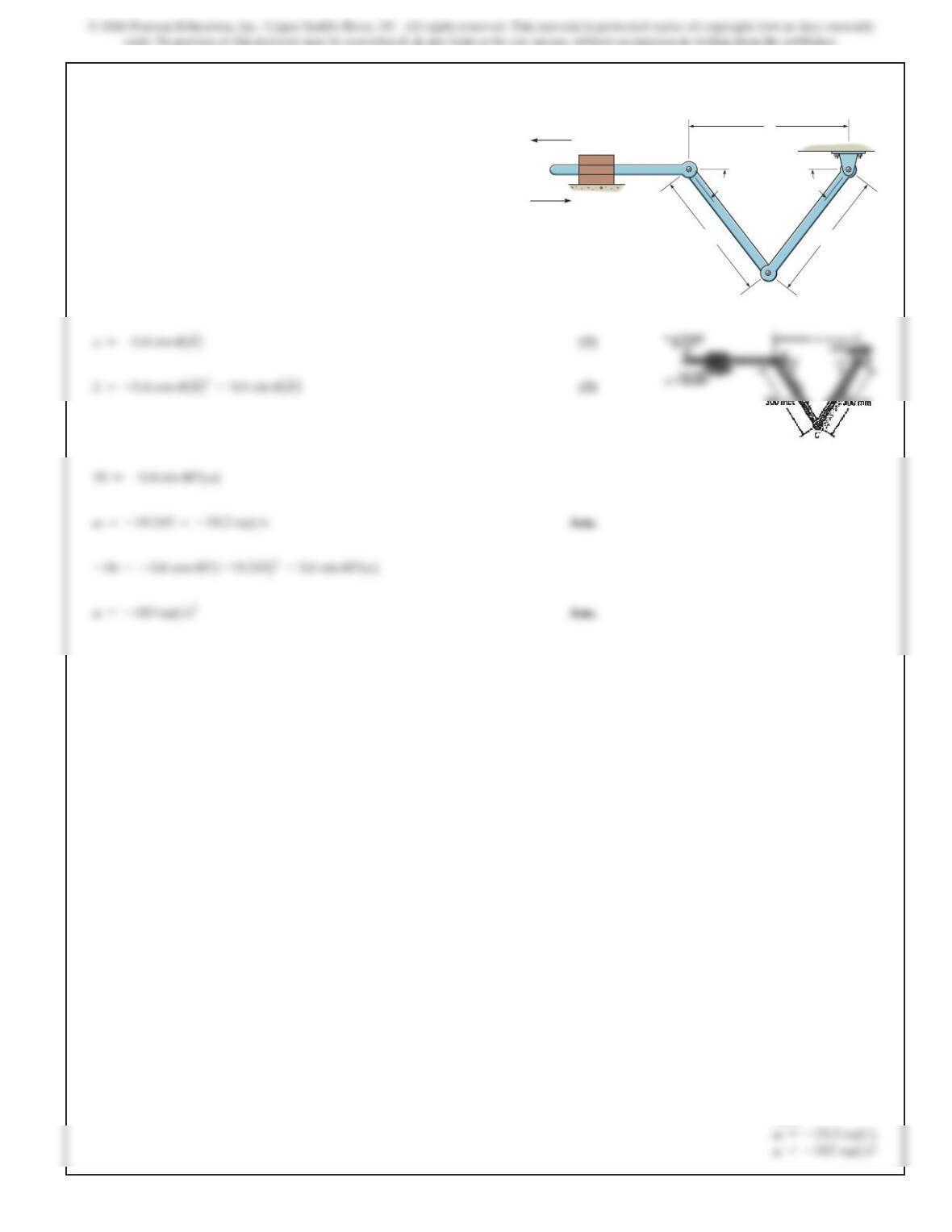
At the instant shown,
u=60°
, and rod AB is subjected to a
deceleration of 16 m
>
s
2
when the velocity is
10 m>s
.
Determine the angular velocity and angular acceleration of
link CD at this instant.
Ans:
SOLUTION
x=2(0.3) cos
u
Using Eqs. (1) and (2) at
u=60°
,
x
#=10 m>s
,
x
$=–16 m>s2
.
300 mm300 mm
D
B
x
C
A
v 10 m/s
a 16 m/s2
uu
672
16–43.
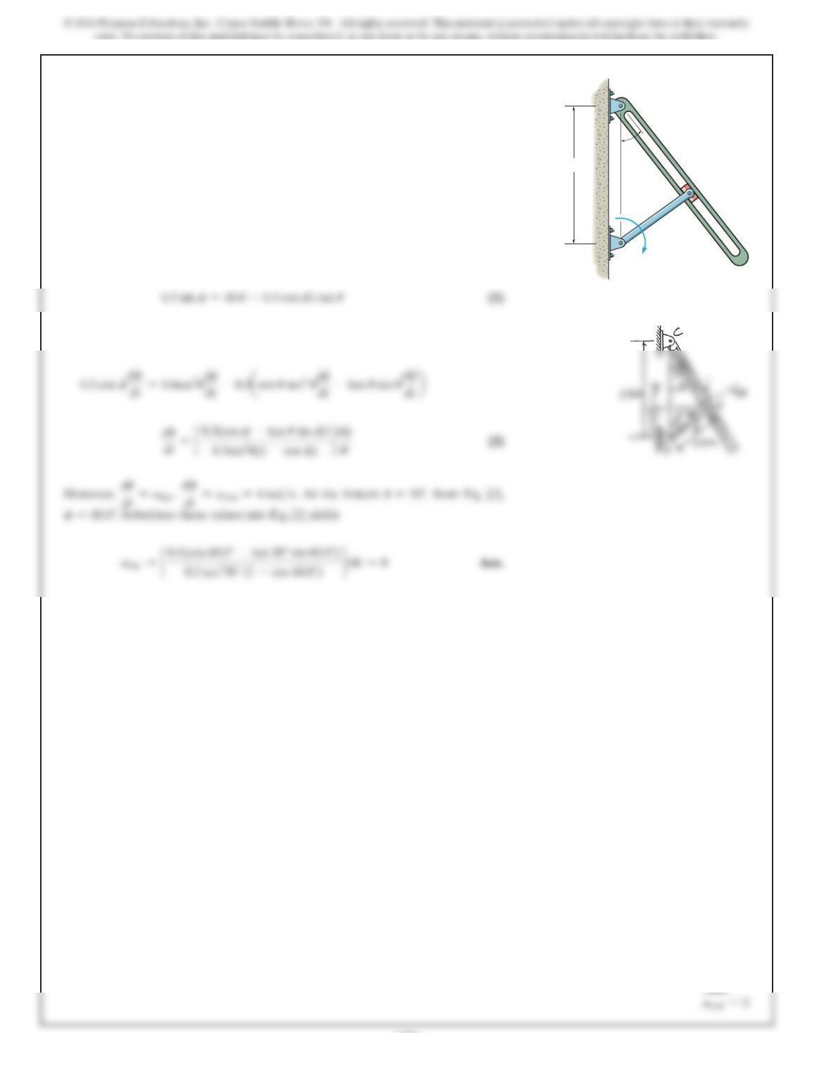
The crank AB is rotating with a constant angular velocity of
4 rad
>
s. Determine the angular velocity of the connecting
rod CD at the instant
u=30°.
Ans:
SOLUTION
Position Coordinate Equation: From the geometry,
Time Derivatives: Taking the time derivative of Eq. [1], we have
u
A
C
B
D
4 rad/s
600 mm
300 mm
673
Ans:
*16–44.
A
C
B
D
r
O
u
v
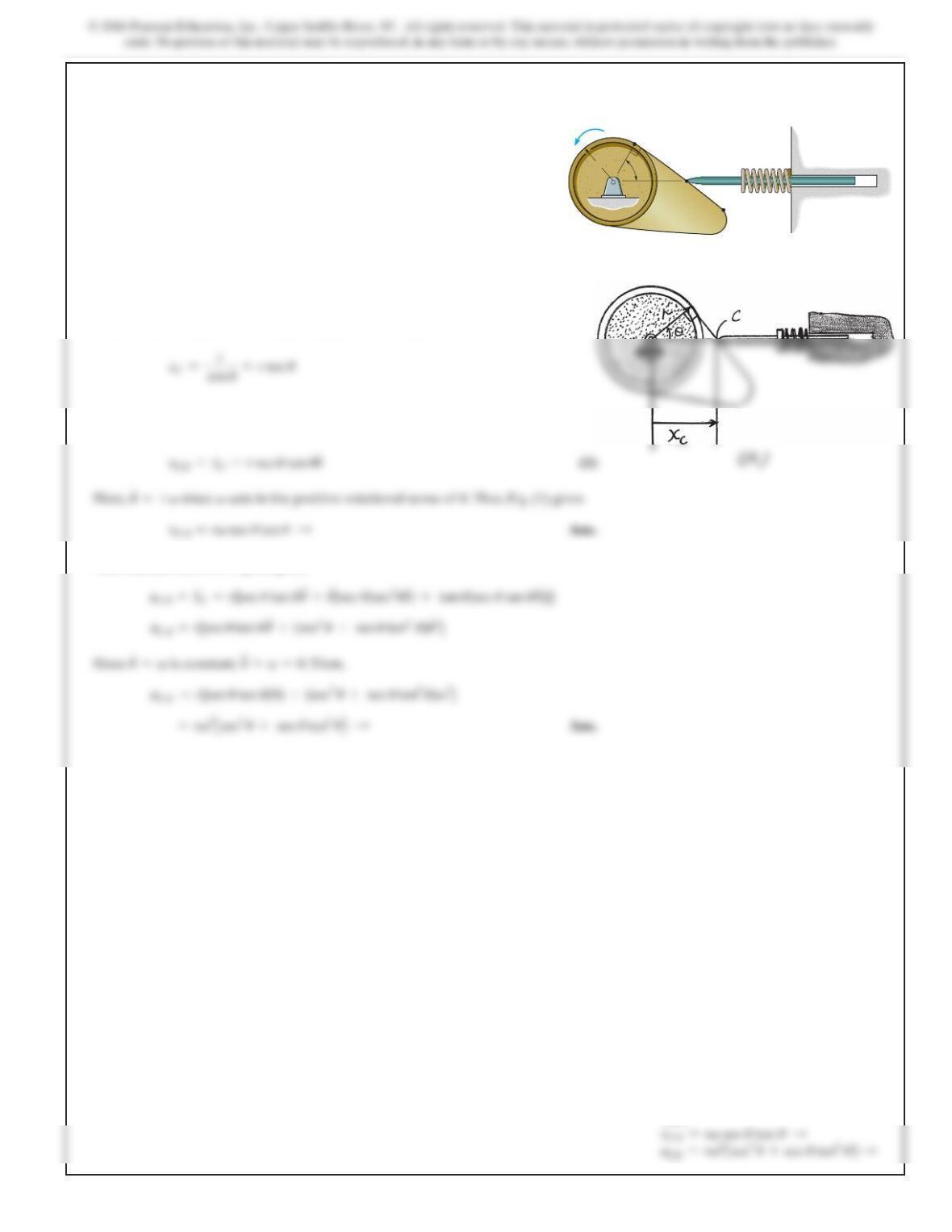
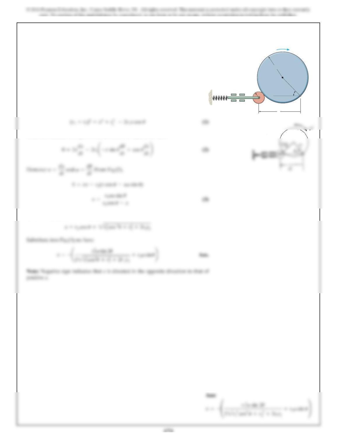
Determine the velocity and acceleration of the follower
rod CD as a function of when the contact between the cam
and follower is along the straight region AB on the face of
the cam. The cam rotates with a constant counterclockwise
angular velocity V.
u
SOLUTION
Position Coordinate: From the geometry shown in Fig. a,
Time Derivative: Taking the time derivative,
The time derivative of Eq.(1) gives
16–45.
SOLUTION
Position Coordinate Equation: Using law of cosine.
Time Derivatives: Taking the time derivative of Eq. (1).we have
However, the positive root of Eq.(1) is
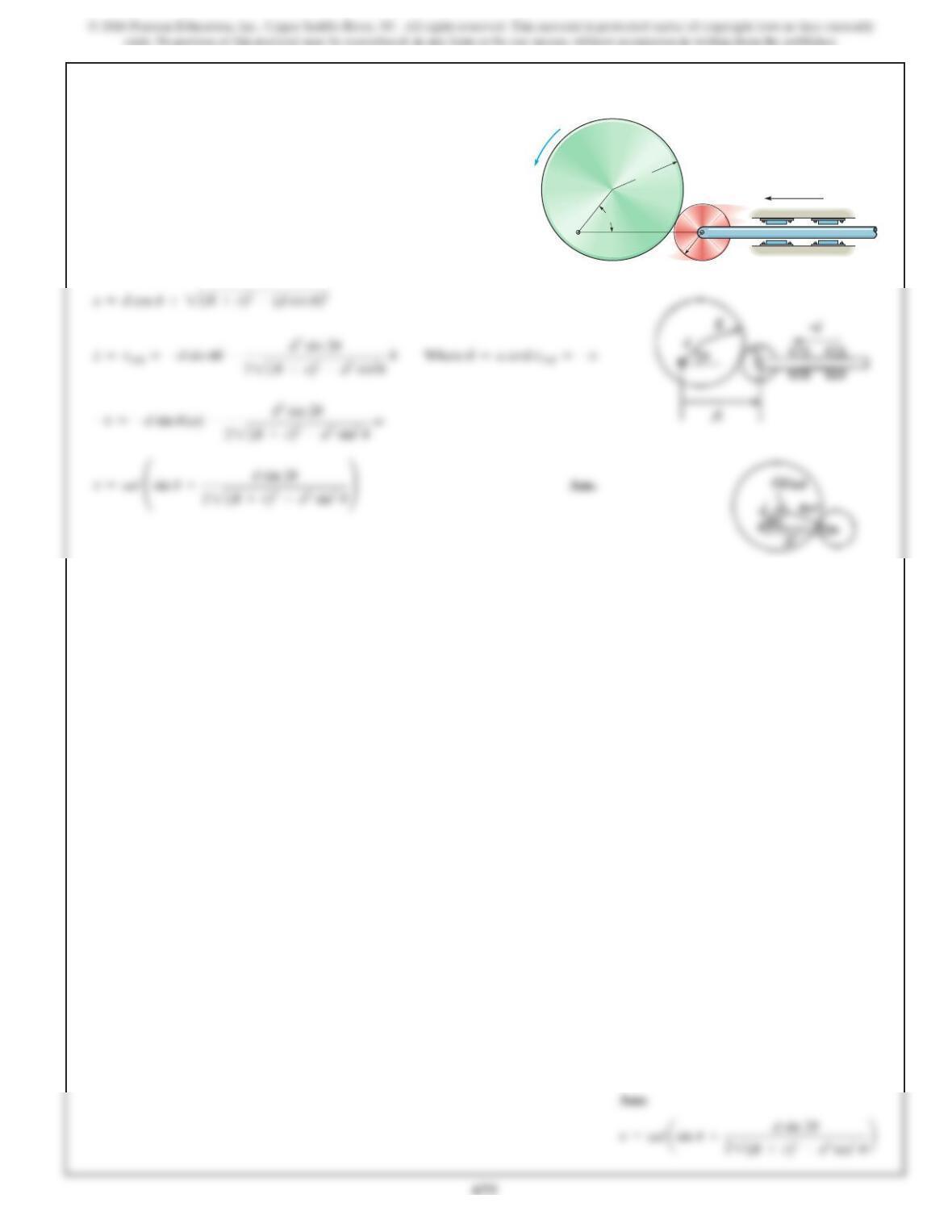
Determine the velocity of rod Rfor any angle of the cam
Cif the cam rotates with a constant angular velocity The
pin connection at Odoes not cause an interference with the
motion of Aon C.
V.
u
C
R
r
2
r
1
A
O
x
V
u
16–46.
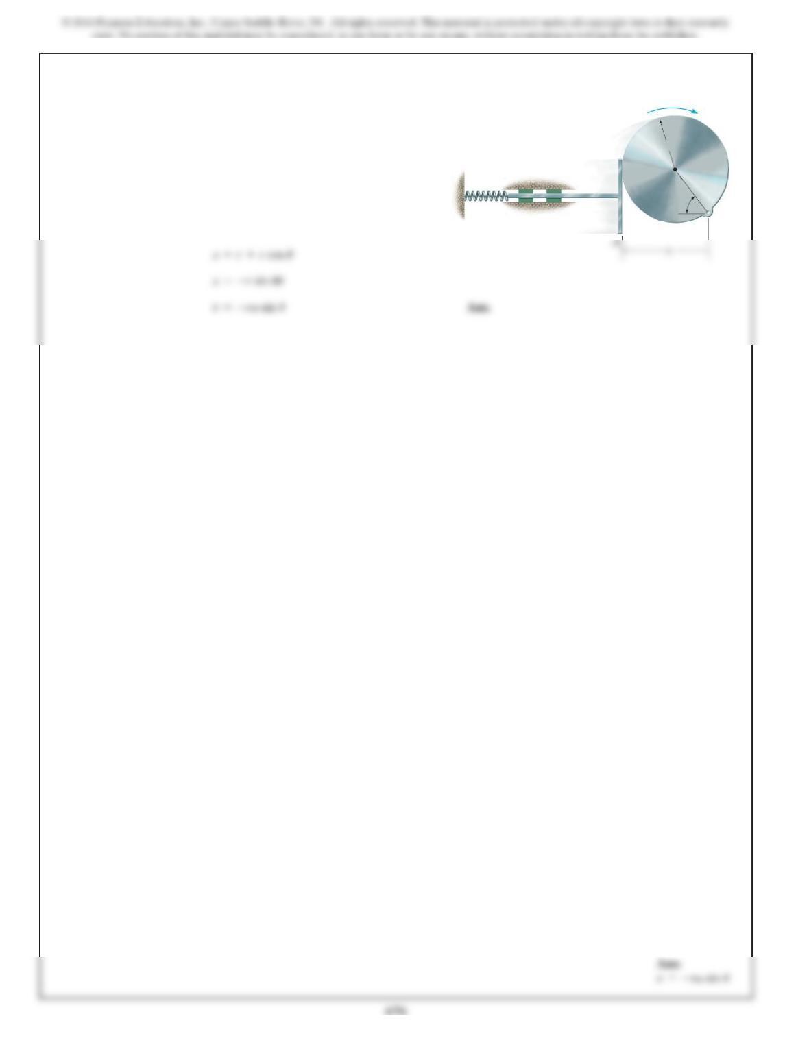
The circular cam rotates about the fixed point O with a
constant angular velocity
V.
Determine the velocity v of the
follower rod AB as a function of
u
.
SOLUTION
u
AB
R
d
r
v
u
O
v
16–47.
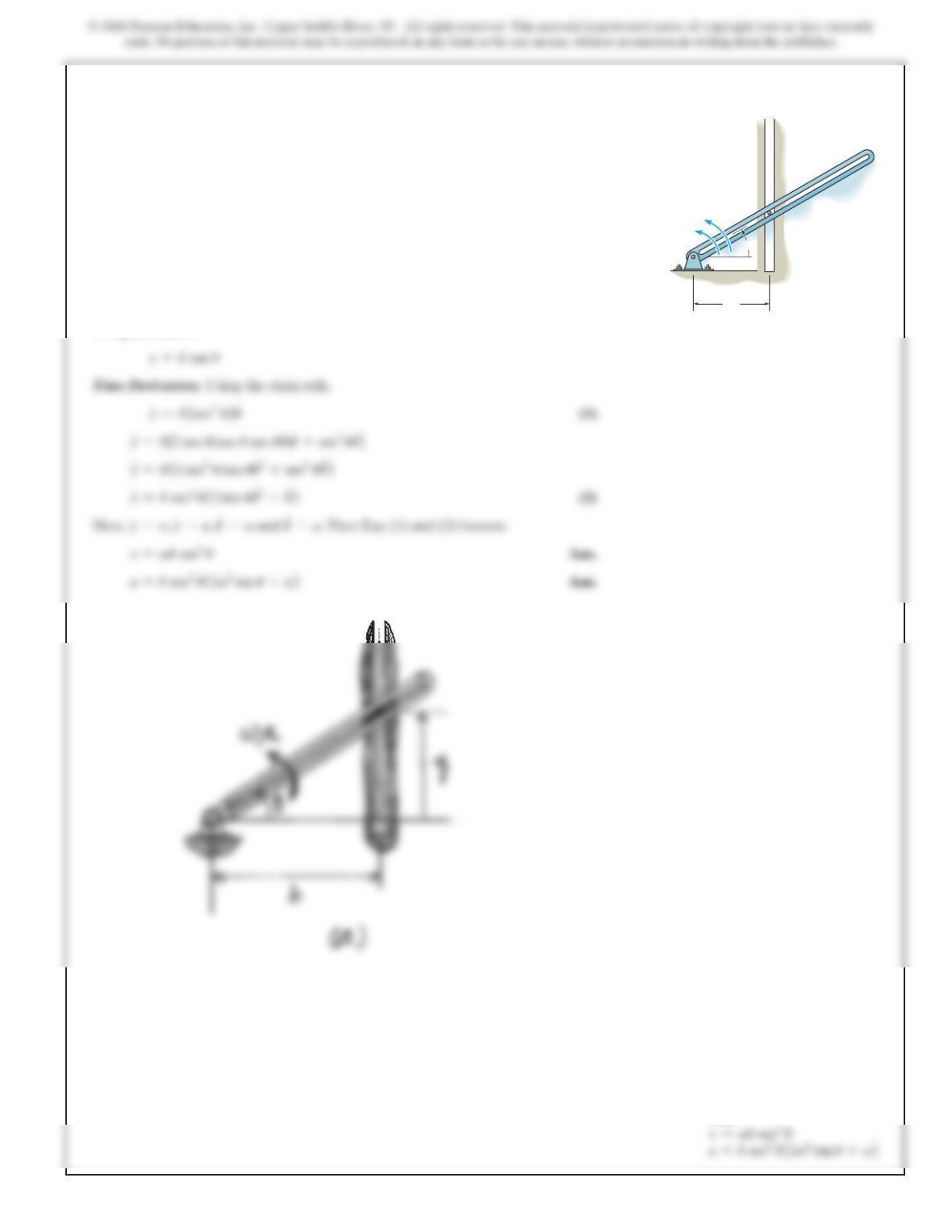
Determine the velocity of the rod Rfor any angle of cam
Cas the cam rotates with a constant angular velocity The
pin connection at Odoes not cause an interference with the
motion of plate Aon C.
V.
u
SOLUTION
u
R
C
r
O
V
677
Ans:
*16–48.
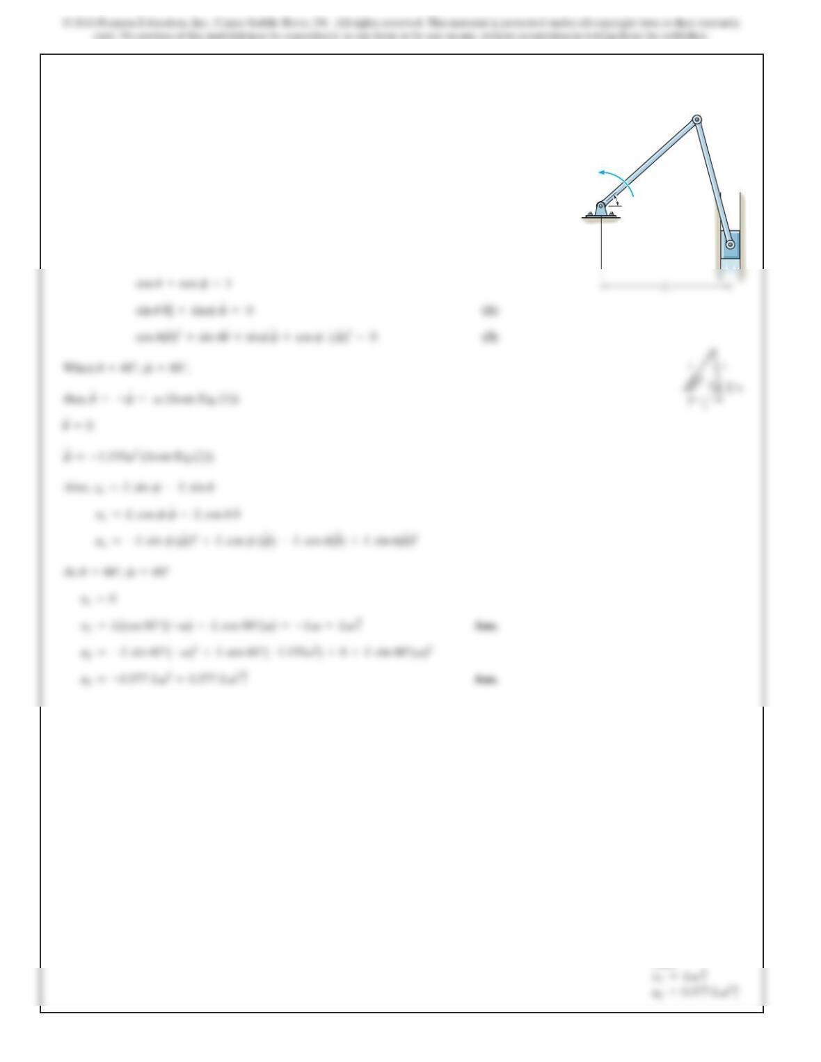
Determine the velocity and acceleration of the peg A which
is confined between the vertical guide and the rotating
slotted rod.
SOLUTION
Position Coordinate Equation. The rectilinear motion of peg A can be related to
the angular motion of the slotted rod by relating y and
u
using the geometry shown
in Fig. a, which is
u
u
A
b
O
v
a
u
678
16–49.
SOLUTION
Lcos u+Lcos f=L
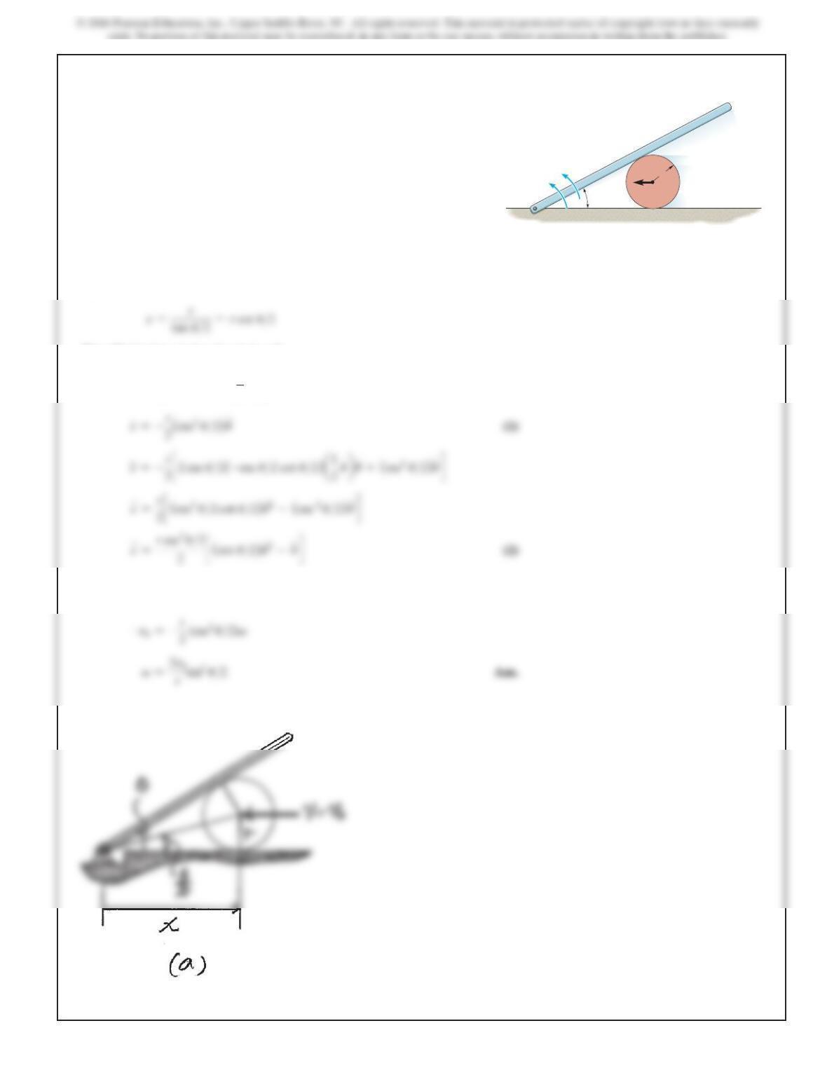
Bar AB rotates uniformly about the fixed pin Awith a
constant angular velocity Determine the velocity and
acceleration of block C, at the instant u=60°.
V.
A
L
L
C
B
u
V
Ans:
679
16–50.
The center of the cylinder is moving to the left with a
constant velocity v0. Determine the angular velocity
V
and
angular acceleration
A
of the bar. Neglect the thickness of
the bar.
SOLUTION
Position Coordinate Equation. The rectilinear motion of the cylinder can be related
to the angular motion of the rod by relating x and
u
using the geometry shown in
Fig. a, which is
Time Derivatives. Using the chain rule,
x
#=r
c
(
–csc2 u
>
2
)
a
1
2
u
#bd
Here
x
$=–v0
since
v0
is directed toward the negative sense of x and
u
#
=v
. Then
Eq. (1) gives,
u
V
Ar
vOO
680
Ans:
15–50. Continued
Also,
x
$=0
since
v
is constant and
u
$
=a
. Substitute the results of
v
into Eq. (2):
16–51.
SOLUTION
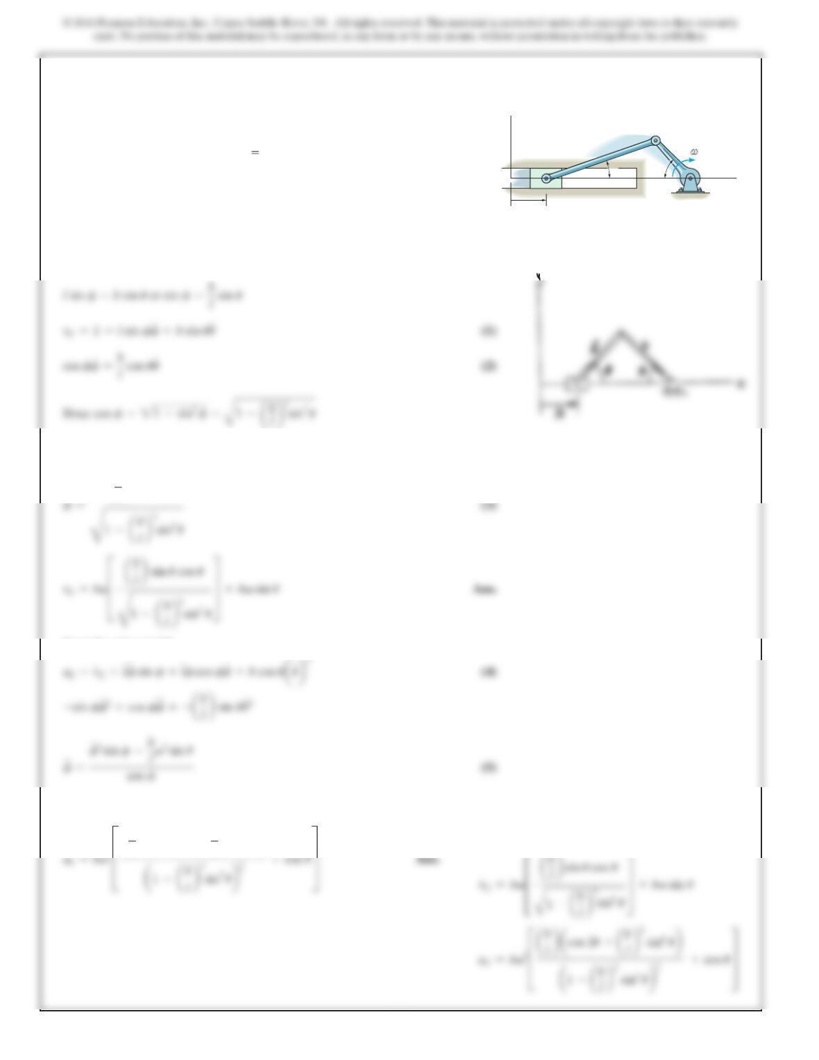
Position coordinate equation:
The pins at Aand Bare confined to move in the vertical
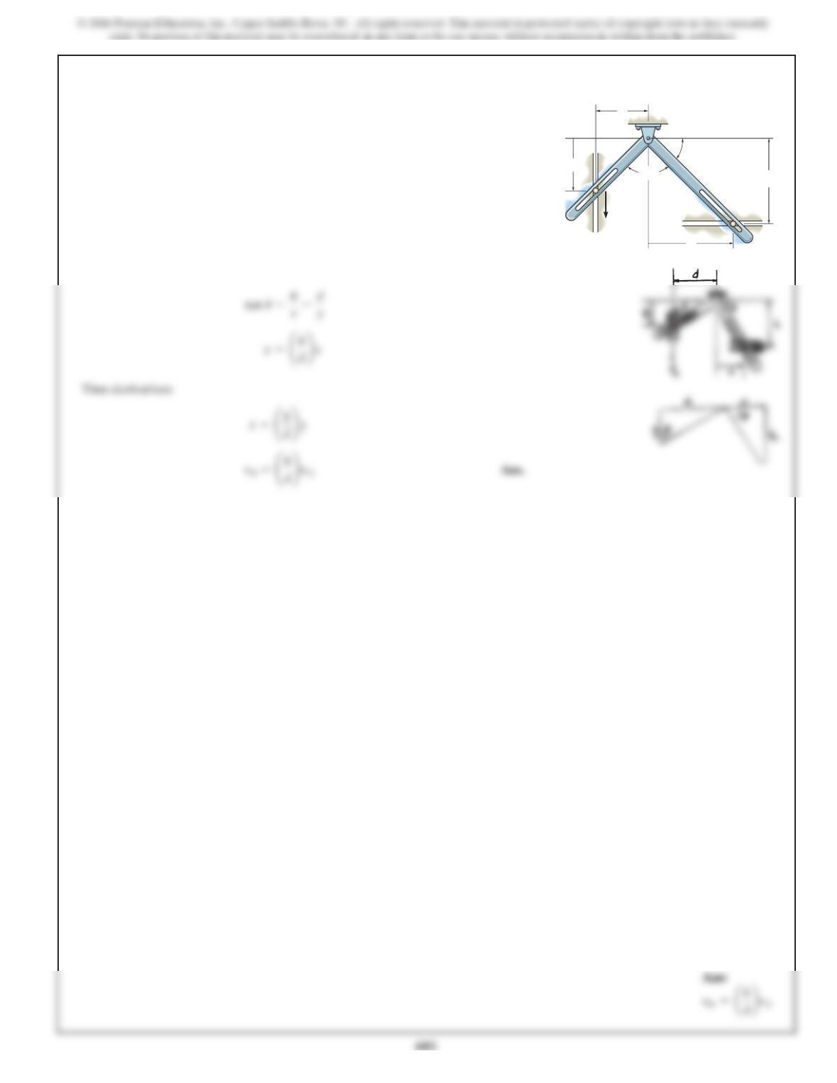
and horizontal tracks. If the slotted arm is causing Ato move
downward at determine the velocity of Bat the instant
shown.
vA,
90°
y
d
h
x
B
A
θ
vA
682
*16–52.
SOLUTION
then,
From Eq. (1) and (2):
Substituting Eqs. (1), (2), (3) and (5) into Eq. (4) and simplifying yields
lbacos 2u+ab
lb2
sin4ub
#=ab
lbcos uv
x=l+b–(Lcos f+bcos u)
The crank AB has a constant angular velocity . Determine
the velocity and acceleration of the slider at Casafunction
of . Suggestion: Use the xcoordinate to express the motion
of Cand the coordinate for CB.x 0 when .f=0°f
u
V
C
B
bl
x
x
y
A
θ
φ
ω
Ans:
16–53.
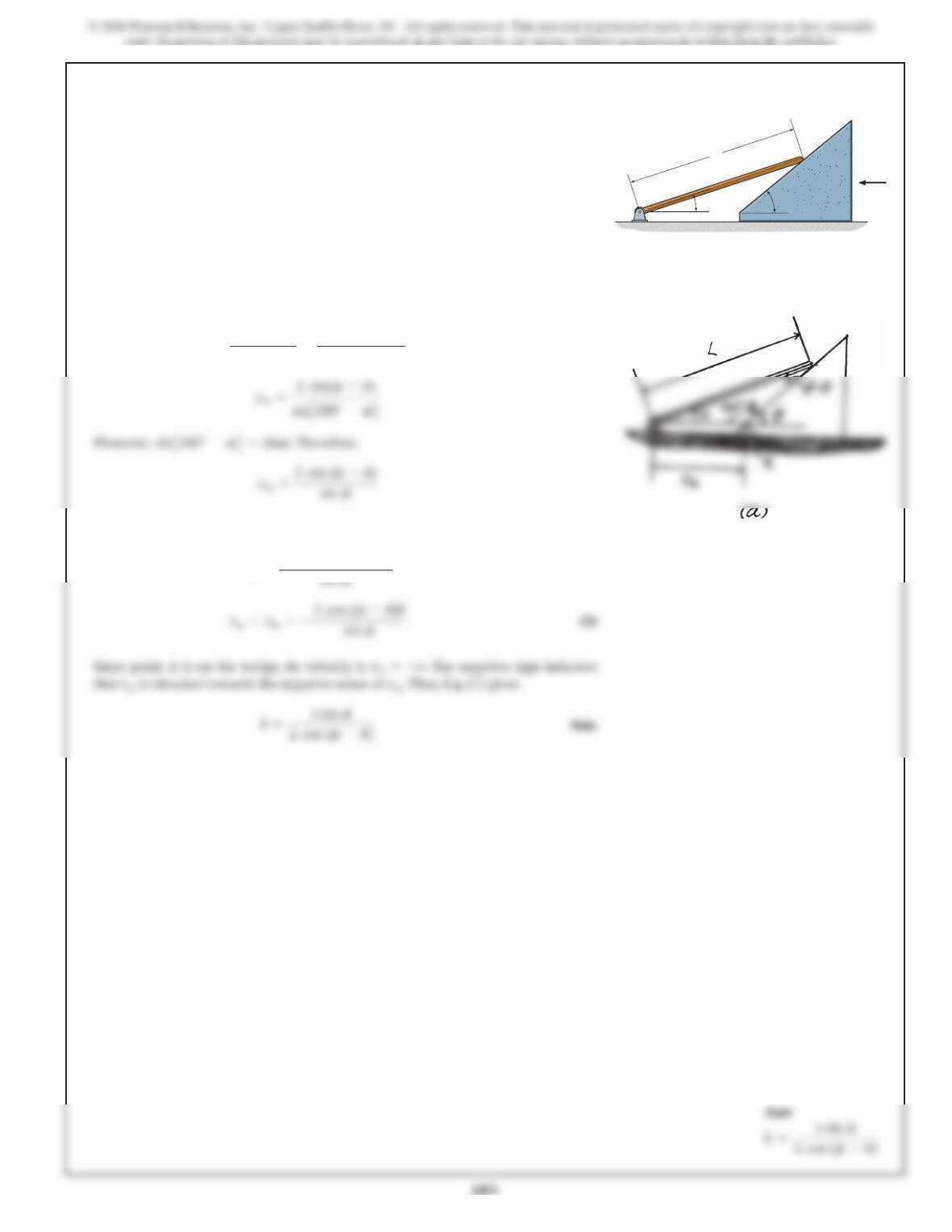
If the wedge moves to the left with a constant velocity v,
determine the angular velocity of the rod as a function of .u
SOLUTION
Position Coordinates:Applying the law of sines to the geometry shown in Fig. a,
Time Derivative:Taking the time derivative,
x
#
A=Lcos (f–u)(–u
#)
xA
sin(f–u)=L
sin
A
180° –f
B
L
v
f
u
16–54.
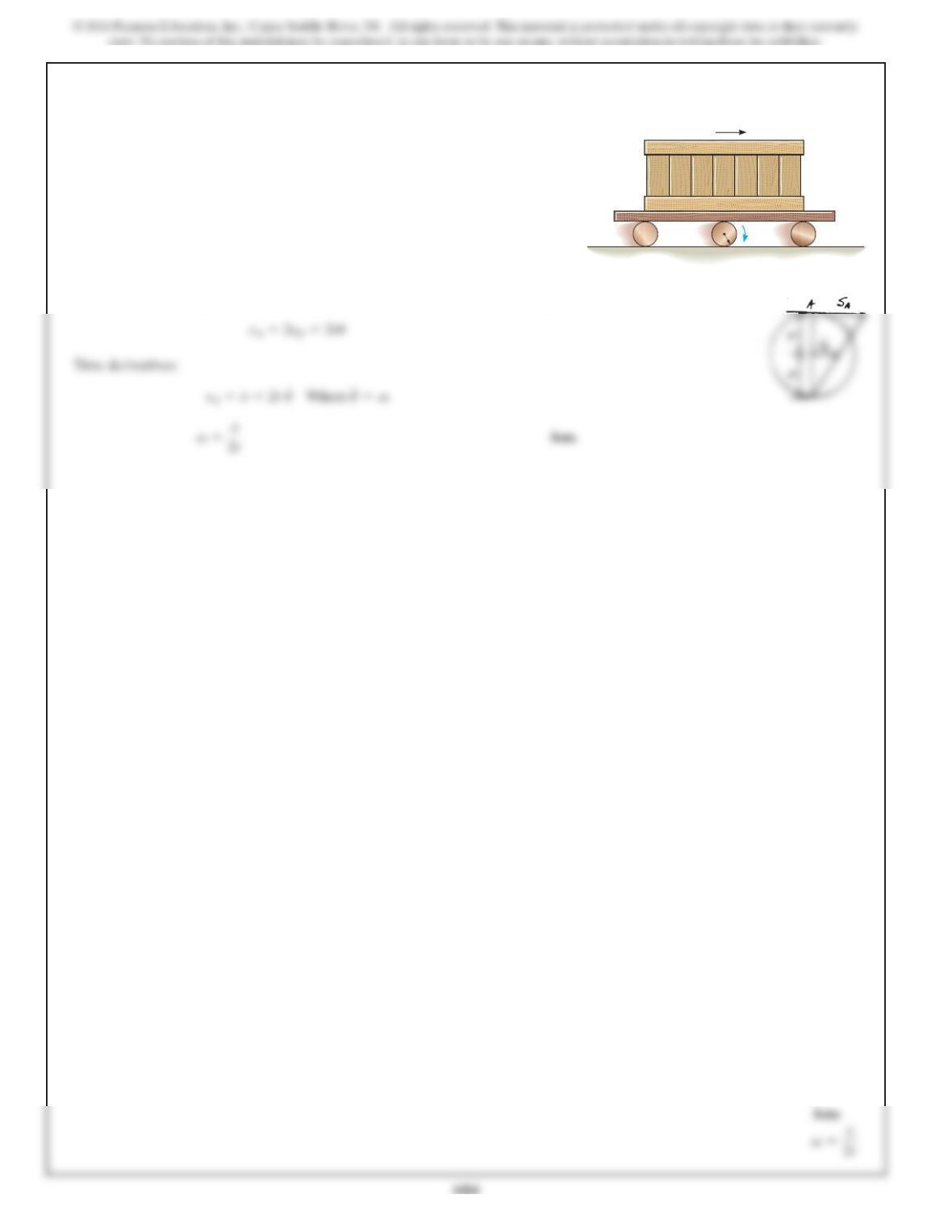
The crate is transported on a platform which rests on
rollers, each having a radius r. If the rollers do not slip,
determine their angular velocity if the platform moves
forward with a velocity v.
SOLUTION
Position coordinate equation: From Example 163, . Using similar triangles
sG=ru
v
rv
685
16–55.
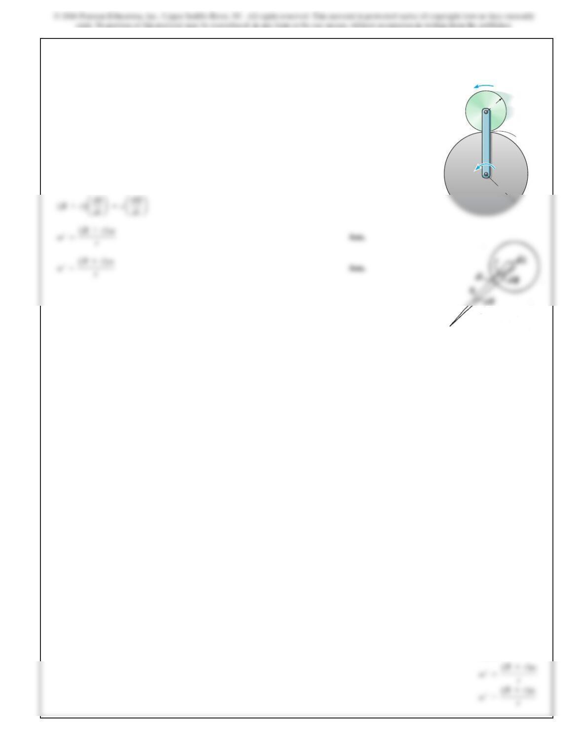
Arm AB has an angular velocity of and an angular
acceleration of . If no slipping occurs between the disk D
and the fixed curved surface, determine the angular velocity
and angular acceleration of the disk.
A
V
SOLUTION
ds =(R+r)du=rdf
B
R
A
D
C
r
ωα
,
ωα
‘,
‘
Ans:
686
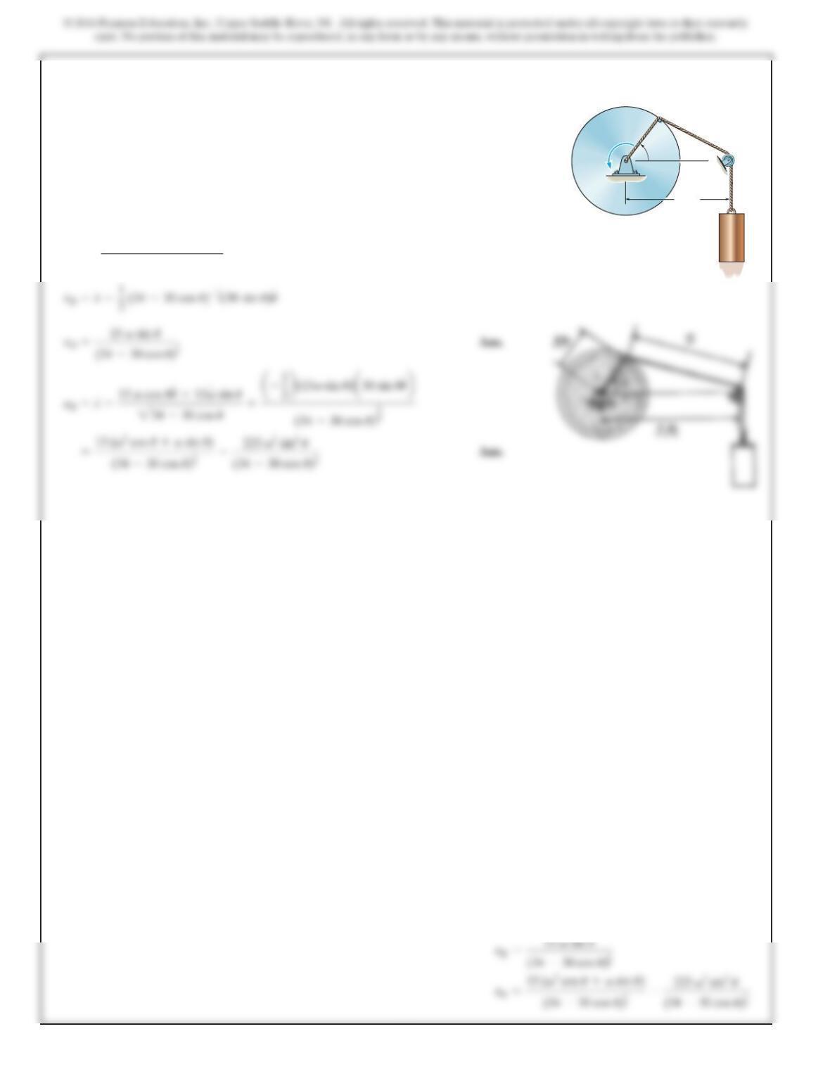
*16–56.
SOLUTION
s=232+52–2(3)(5) cos u
At the instant shown, the disk is rotating with an angular
velocity of and has an angular acceleration of .
Determine the velocity and acceleration of cylinder Bat
this instant. Neglect the size of the pulley at C.
AV 3ft
5ft
A
V,AC
u
B
Ans:
687
16–57.
SOLUTION
Also;
vB=vG+v*rB>G
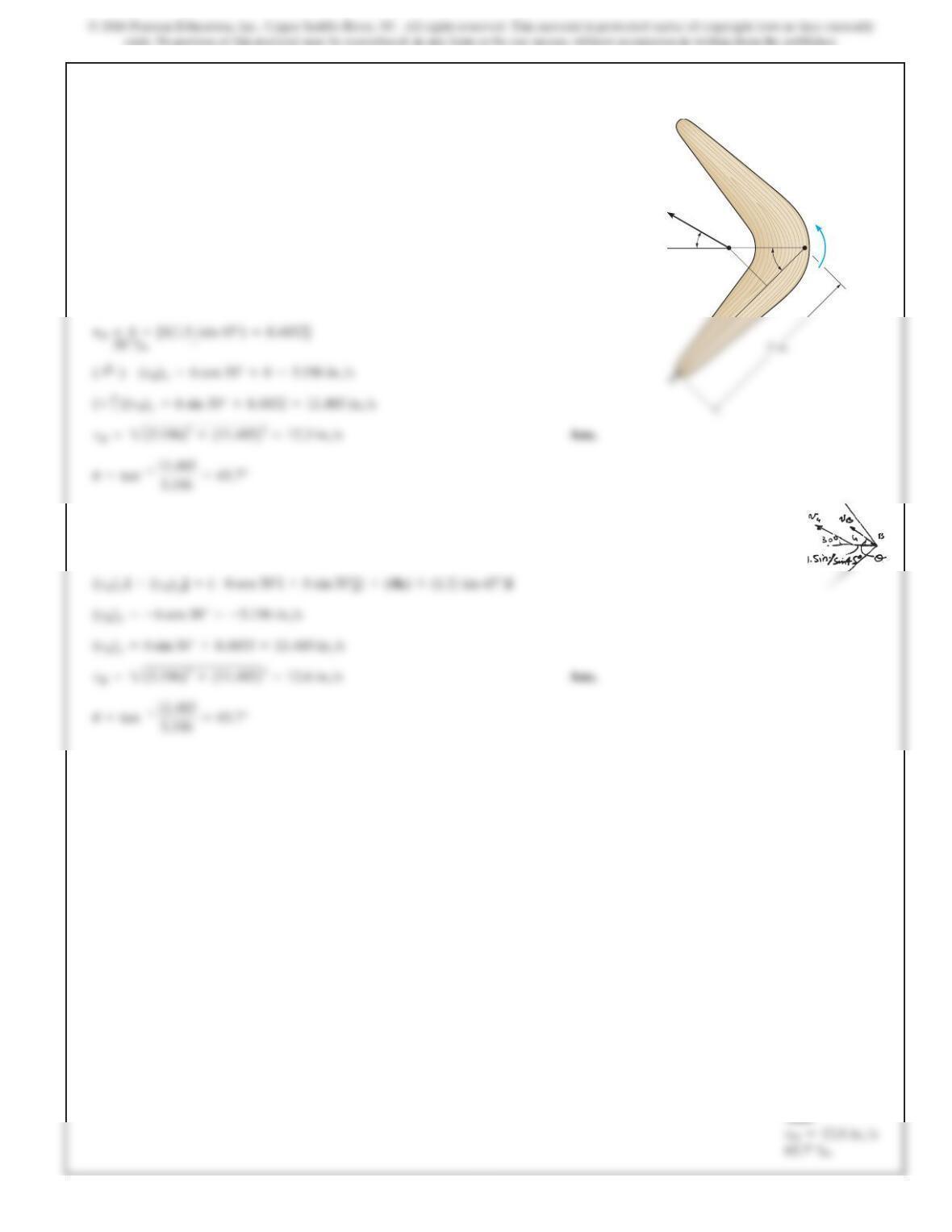
vB=vG+vB>G
At the instant shown the boomerang has an angular velocity
and its mass center Ghas a velocity
Determine the velocity of point Bat this
instant.
vG=6 in.>s.
v=4 rad>s,
45°
30°
1.5 in.
GB
=4rad/s
ω
v
G=6in./s
Ans:
688
16–58.
SOLUTION
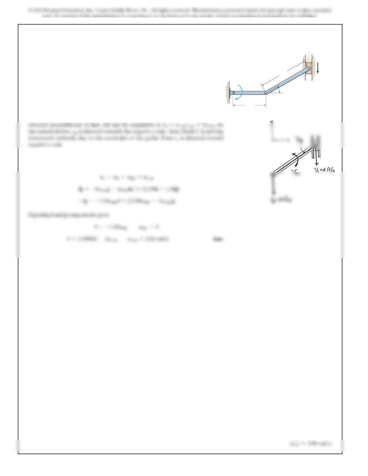
Kinematic Diagram:Since link AB is rotating about fixed point A,then vBis always
Velocity Equation:.,ereH
Applying Eq. 16–16, we have
rC>B={3 cos 30°i+3 sin 30°j}ft={2.598i+1.50j}ft
If the block at Cis moving downward at 4 ft
/
s, determine
the angular velocity of bar AB at the instant shown.
A
B
AB
C
2ft
3ftvC=4ft/s
30°
ω
Ans:
689
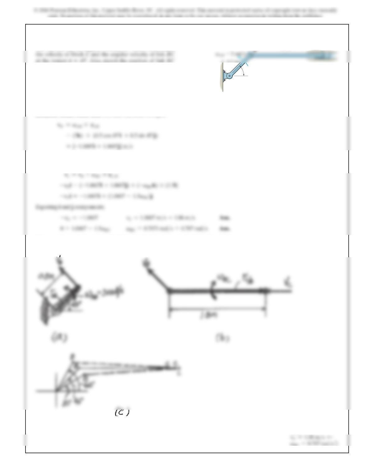
16–59.
The link AB has an angular velocity of 3 rad
>
s. Determine
u=45°
when u
=60°, 45°,
and 30° to show its general plane motion.
Ans:
BC =0.707
SOLUTION
Rotation About Fixed Axis. For link AB, refer to Fig. a.
General Plane Motion. For link BC, refer to Fig. b. Applying the relative velocity
equation,
The general plane motion of link BC is described by its orientation when
u=30°
,
45
°
and 60
°
shown in Fig. c.
1.5 m
0.5 m
45
u
A