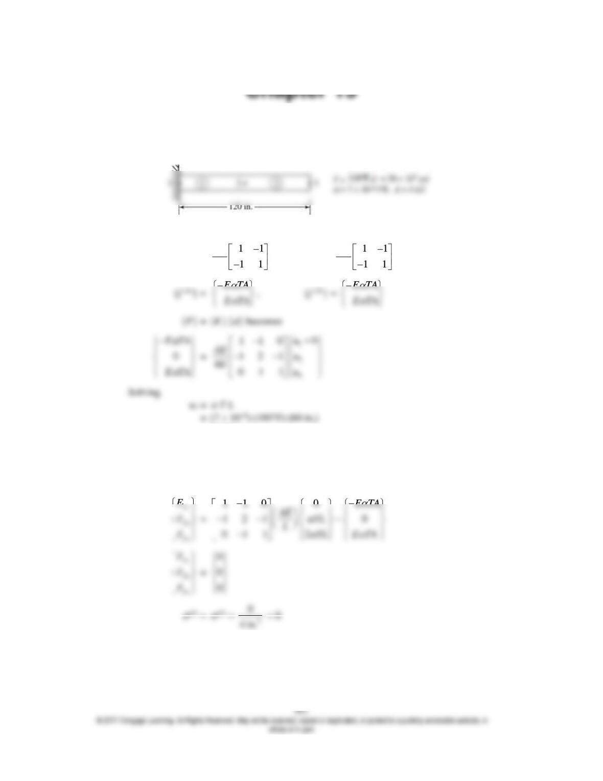
15.1
1 2 2 3
[k(1)] =
11
11
60
AE
, [k(2)] =
11
11
60
AE
E TA
E TA
= 0.042 in.
u3 = 2
T L = 0.084 in.
Reactions and actual nodal forces
{F} = [K] {d} – {F0}
1
x
F
1
x
F
1 1 0 0
E TA
AE TL
2
4 in.
15.2
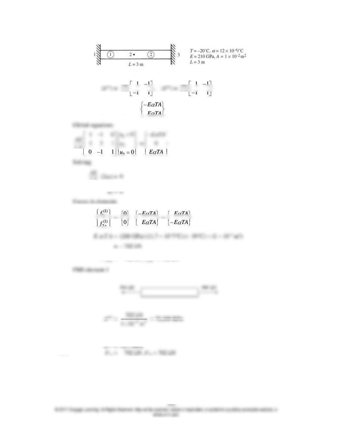
11
AE
11
AE
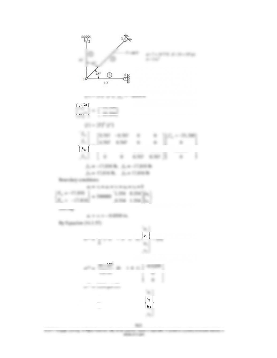
(2)
3
x
f
25,200
{f } = [T ]T {f
}
1
1
3
3
x
y
x
y
f
f
f
f
=
1
0.707 0.707 0 0 25,200
0.707 0.707 0 0 0
0 0 0.707 0.707 25,200
0 0 0.707 0.707 0
x
f
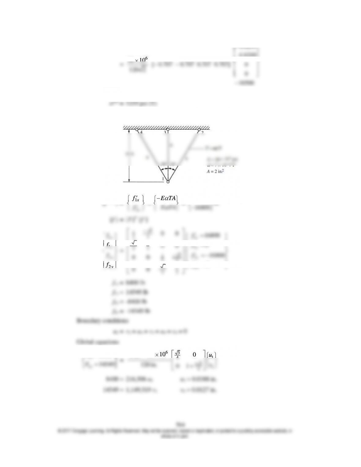
6
30 10
120 2
0.0209
–0.0209
0
10500
(2) = – 7381 psi (C)
(3) = 5219 psi (T)
15.4
1
2
x
x
f
f
E TA
E TA
16800 lb
16800
{f } = [T ]T {f
}
1
1
x
y
f
f
3
1
22 1
311
22
00 16800
0
00
x
y
f
f
(1) =
E
1
1
u
v
{f (1)} =
E TA
E TA
E
L
1
1
4
2
2
0
0
2.88 10
0
u
vET
u
v
=
E
L
(2.88 10–4) – E
T
(1) = – 38.4 MPa (C)
9
200 10
4
2.88 10
00
33
11
4 4 4 4
3 3 3
4 4 4
AE
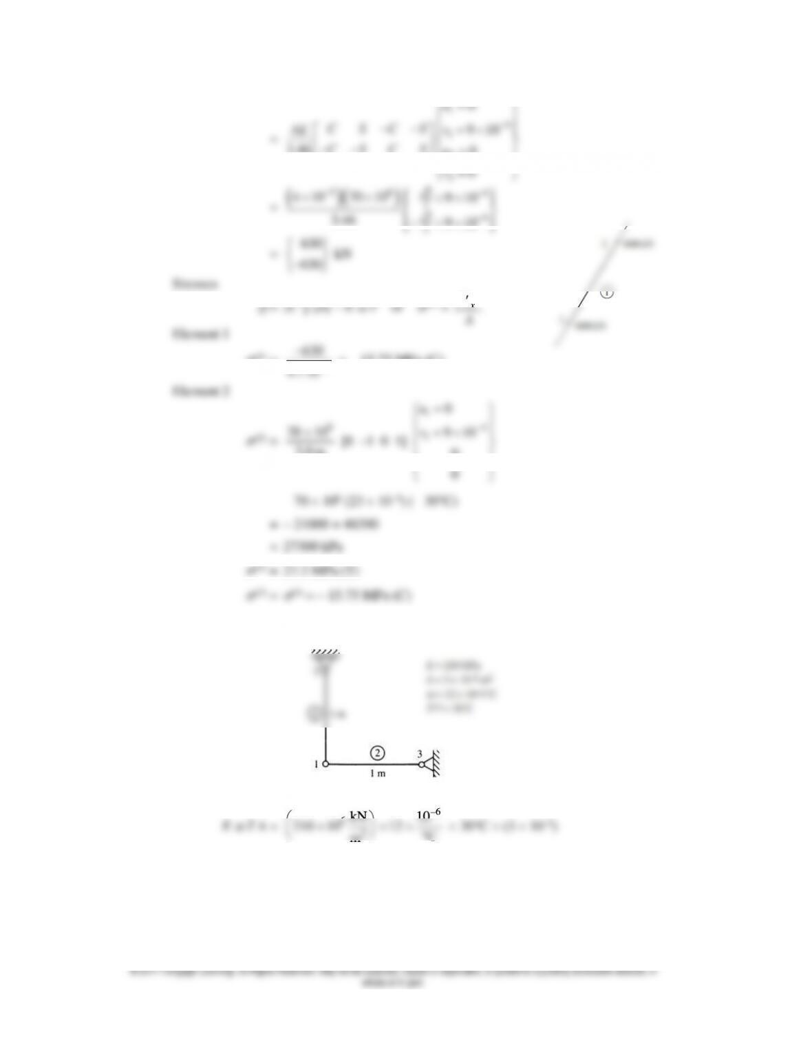
1
4
1
0
9 10
u
C S C S v
AE
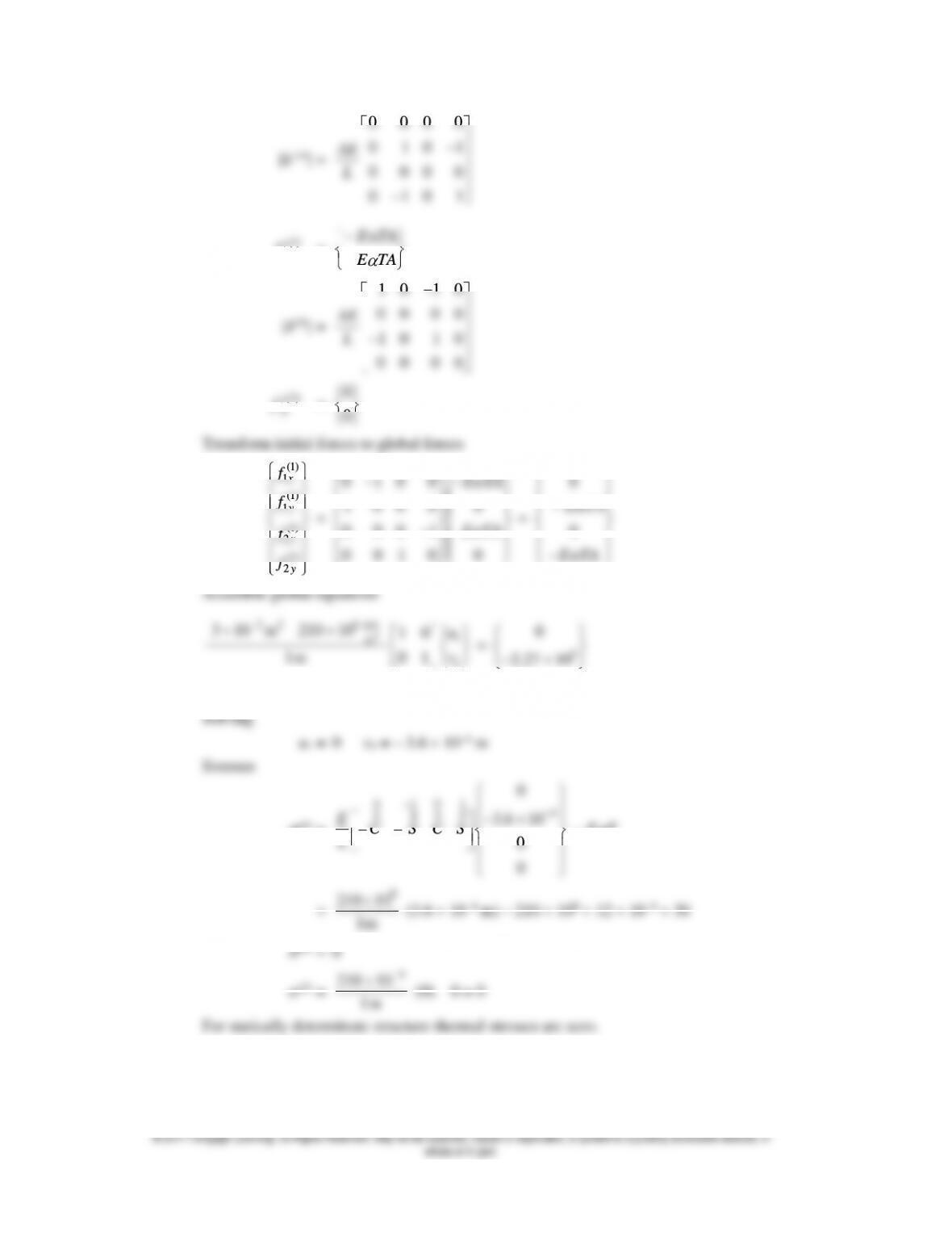
0 0 0 0
0 1 0 1
0 0 0 0
0 1 0 1
AE
L
(1)
0
f
=
E TA
E TA
1 0 1 0
0 0 0 0
1 0 1 0
0 0 0 0
AE
L
(2)
0
f
=
0
0
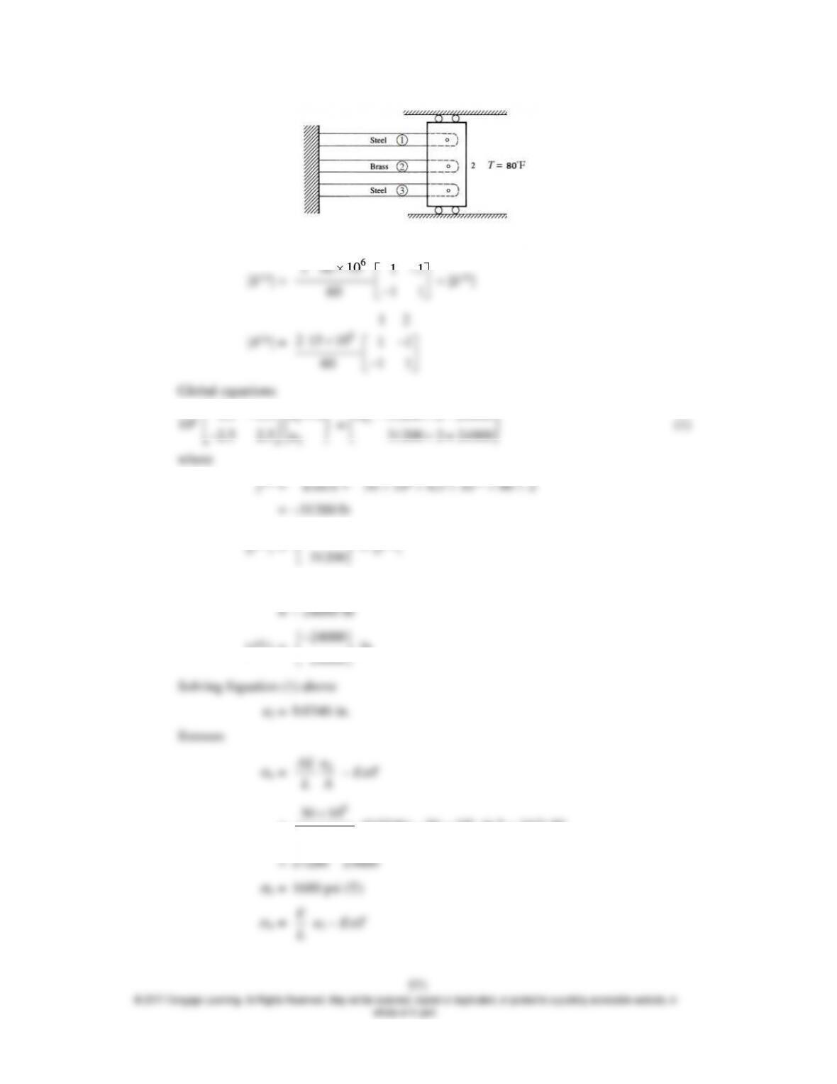
6
2 30 10 11
11
60
[k(2)] =
6
12
2 15 10 11
11
60
Global equations
1
0
2.5 2.5
u
131200 2 24000
x
F
31200
f
(2) = 15 106 10 10–6 80 2
24000
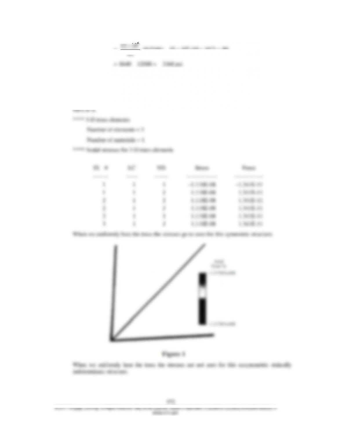
=
6
15 10
60
(0.0346) – 15 106 (10 10–6) 80
15. 9 A uniform temperature increase of 10°C in each element yields zero stress for this special
symmetric arrangement of the truss elements. See the table and figure 1 below showing the
stresses from Autodesk to be zero in each element of the truss.
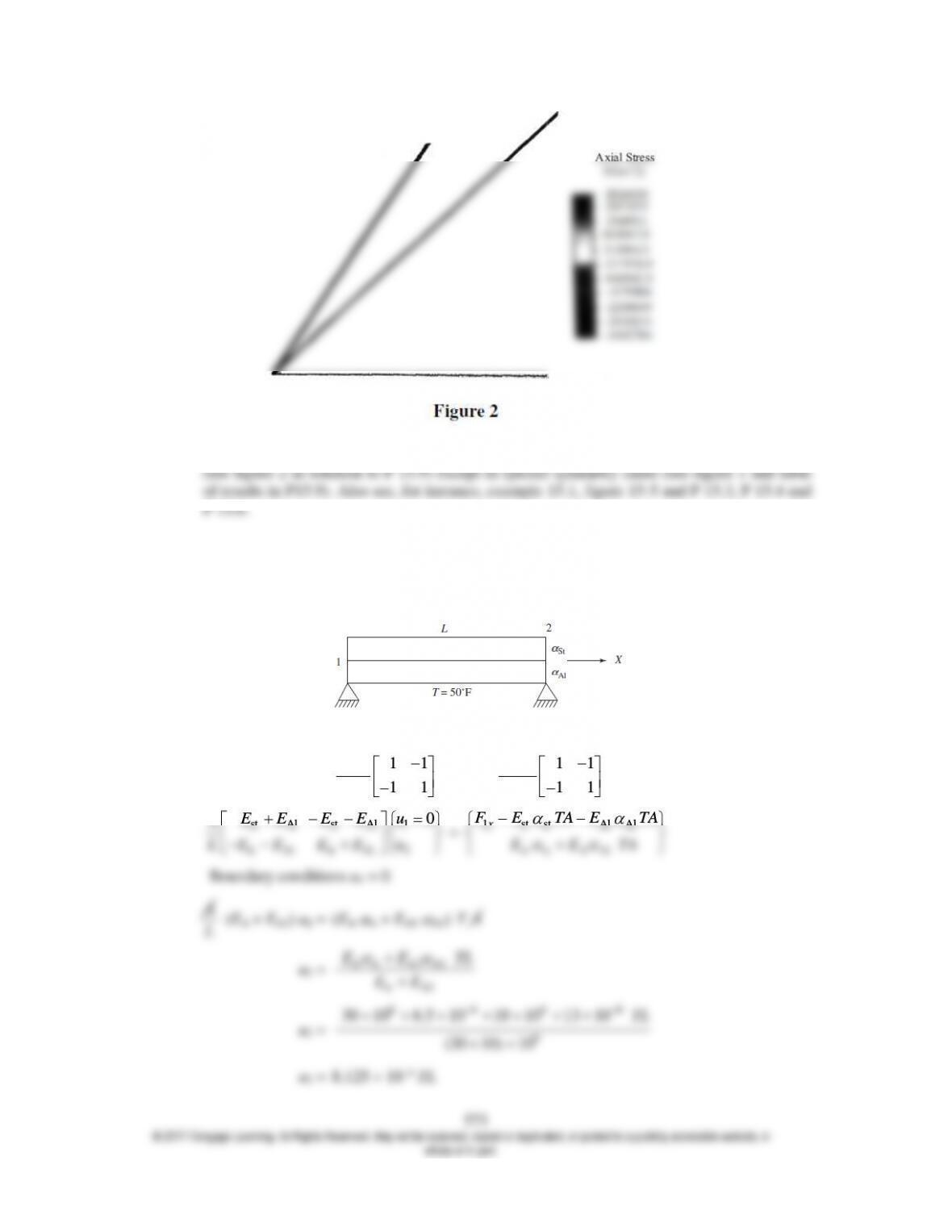
Note that if the truss is not symmetric as shown in figure 2 and then is uniformly heated, the
middle element has a stress of –3.46 MPa in it, while the top element has a stress of 2.83
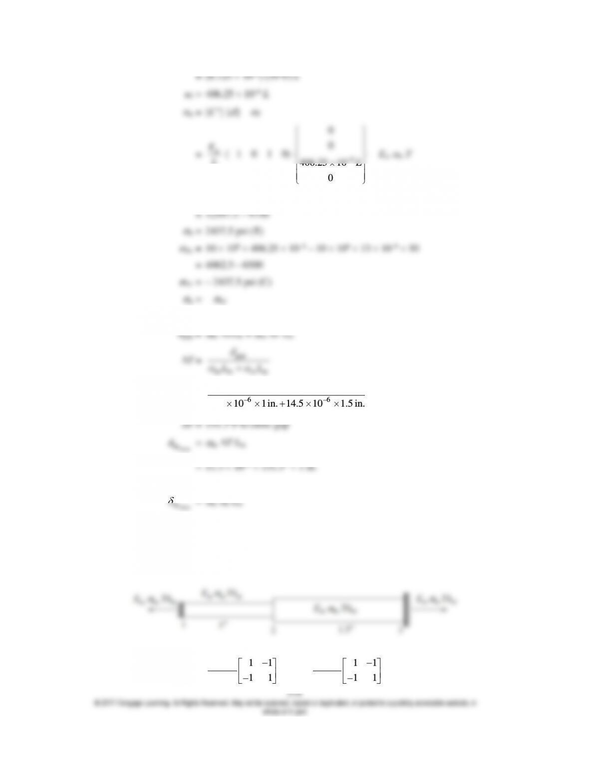
15.10 Bodies that are statically indeterminate will have stress due to uniform temperature change.
15.11
[k
st] =
st 11
11
AE
L
, [k
A1] =
Al 11
11
AE
L
st Al st Al 1
0
E E E E u
A
1 st st Al Al
x
F E TA E TA
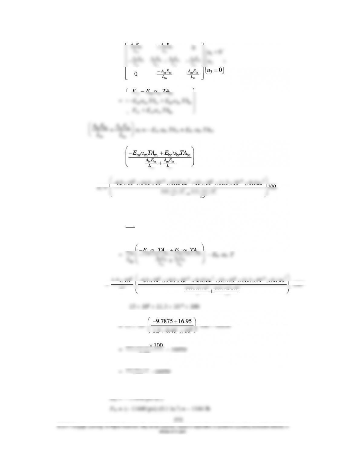
br br br br
br br
br br br br m m m m
1
00
A E A E
LL
A E A E A E A E
u