
104
CHAPTER 13
ELECTRICAL DESIGN AND WIRING
OVERVIEW
After the introduction of basic physics, equipment and systems, and life safety
and communications (auxiliary) of electrical systems, we are now ready to try designing
and preparing the electrical plans for building electrical systems. Naturally, we can only
get a flavor of the electrical design process. For the first time, students can apply their
new-found knowledge usefully. Well-motivated students will find this chapter
interesting and challenging. You may want to assign individuals or groups of students
homework, such as the wiring of the lighting and receptacles of the classroom where the
class is being held, or the wiring of their home or apartment.
105
CHAPTER 13
ELECTRICAL DESIGN AND WIRING
QUESTIONS AND ANSWERS
13.1 Although electrical equipment does not require as much space as most
mechanical equipment, the design of electrical systems and the layout of
electrical components demand even closer interfacing with the architectural
elements in space. Why?
13.2 What are the sequential steps in electrical design? Must they be followed in
the same sequential order?
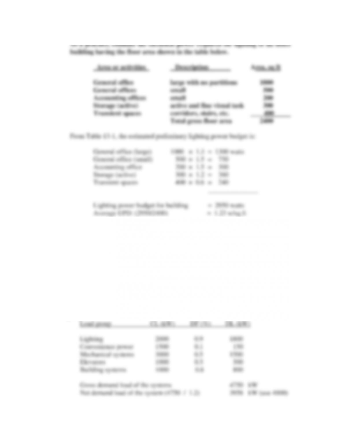
13.3 Unit power density (UPD) is a suggested allowance or budget of electrical power
for lighting in a building. It is given in watts per square foot of the floor area.
The UPD values may be conveniently used for estimating the amount of electrical
power required for spaces or buildings during the preliminary planning phase.
It, however, is not intended for final lighting design, which varies widely in layout
and in the selection of light sources.
106
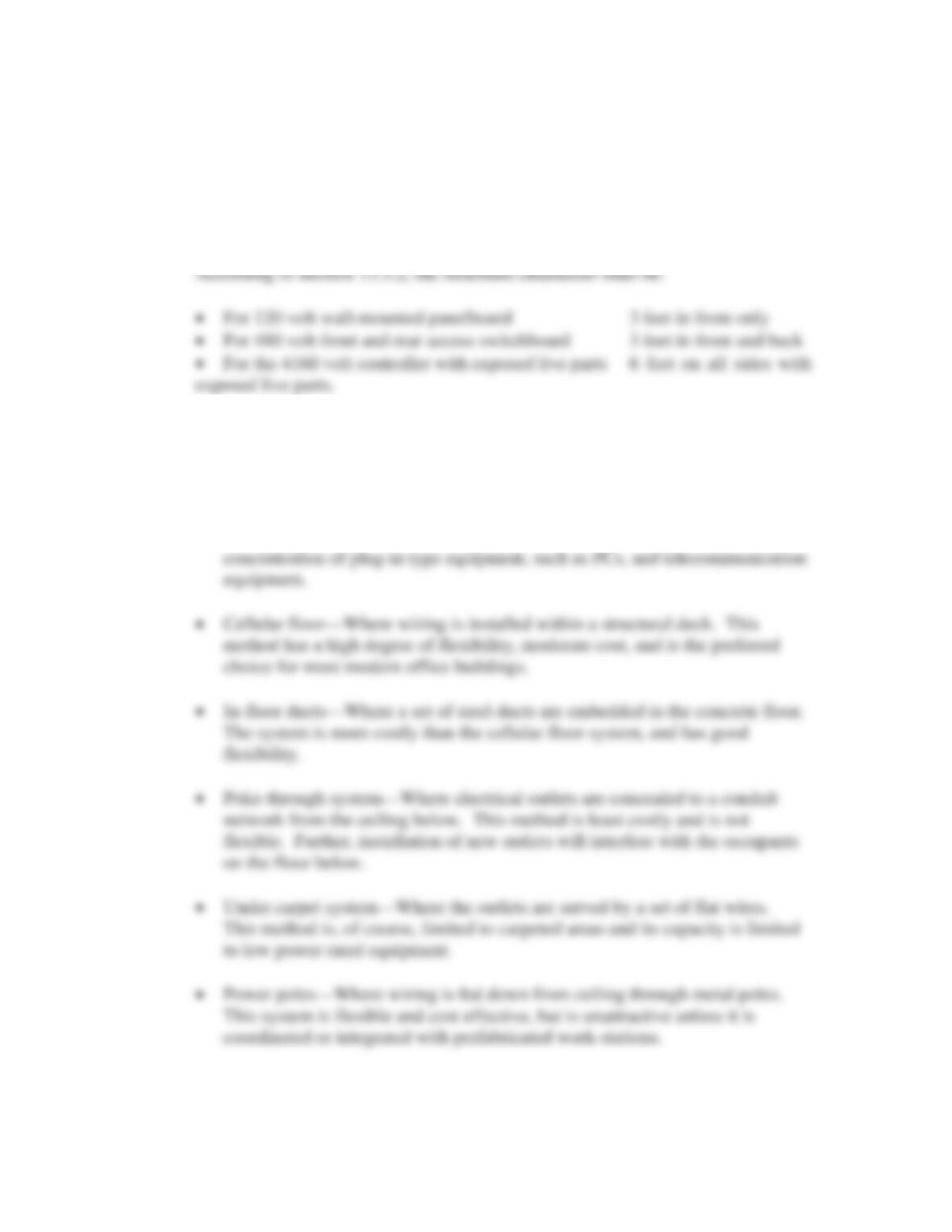
13.4 Determine the gross and the demand loads of a power distribution for a large
building complex with the following design data.
x
Lighting 2000 kW connected, with 0.9 DF
x
Convenience power 1500 kW connected, with 0.1 DF
x
Mechanical systems 3000 kW connected, with 0.5 DF
x
Elevators 1000 kW connected, with 0.5 DF
x
Building systems 1000 kW connected, with 0.8 DF
x
Estimated diversity Coefficient 1.2
The gross demand load of the system is the sum of the demand load of all load
groups:
107
13.5 For safety reasons, adequate clearance must be maintained around the front
and any side with access to the interior of all electrical equipment. What is
the minimum clearance for a 120 volt wall-mounted panelboard? A free-
standing 480 volt switchboard with rear access? And a 4160 volt controller
which is not totally enclosed?
13.6 Name several methods for providing convenience electrical power to the
middle of a space not accessible from wall outlets.
The commonly used methods are:
x Raised floor—This is most flexible and costly. It is used when there is a
108
13.7 What is the difference between a schematic or elementary diagram and a
connection or wiring diagram?
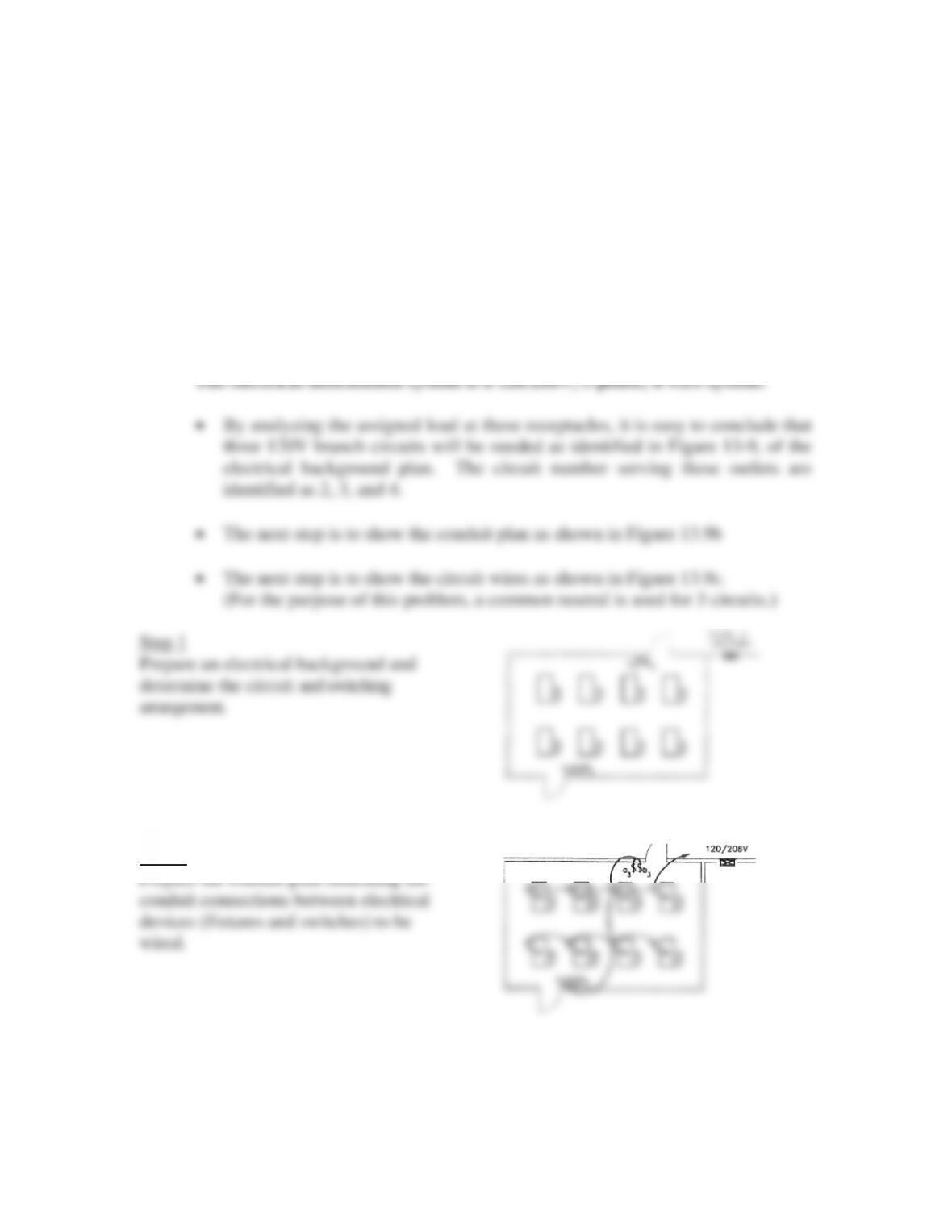
13.8 A room is installed with 8 fluorescent fixtures. Each fixture uses 3
fluorescent lamps totaling 150 watts, including the ballast. It is desired to
switch on and off the center lamp of each fixture for low level of illumination
and the other 2 lamps by another switch for median level of illumination.
Switching on all 3 lamps will provide the highest level. The switches should
be accessible from either of the 2 entries to the room. The room
configuration, lighting layout, and switching locations are shown in the floor
plan below. Determine the number of branch circuits required, and prepare
the branch circuit wiring plan.
x The total power of the lights is 1200 watts. It is within the normal rating of a
109
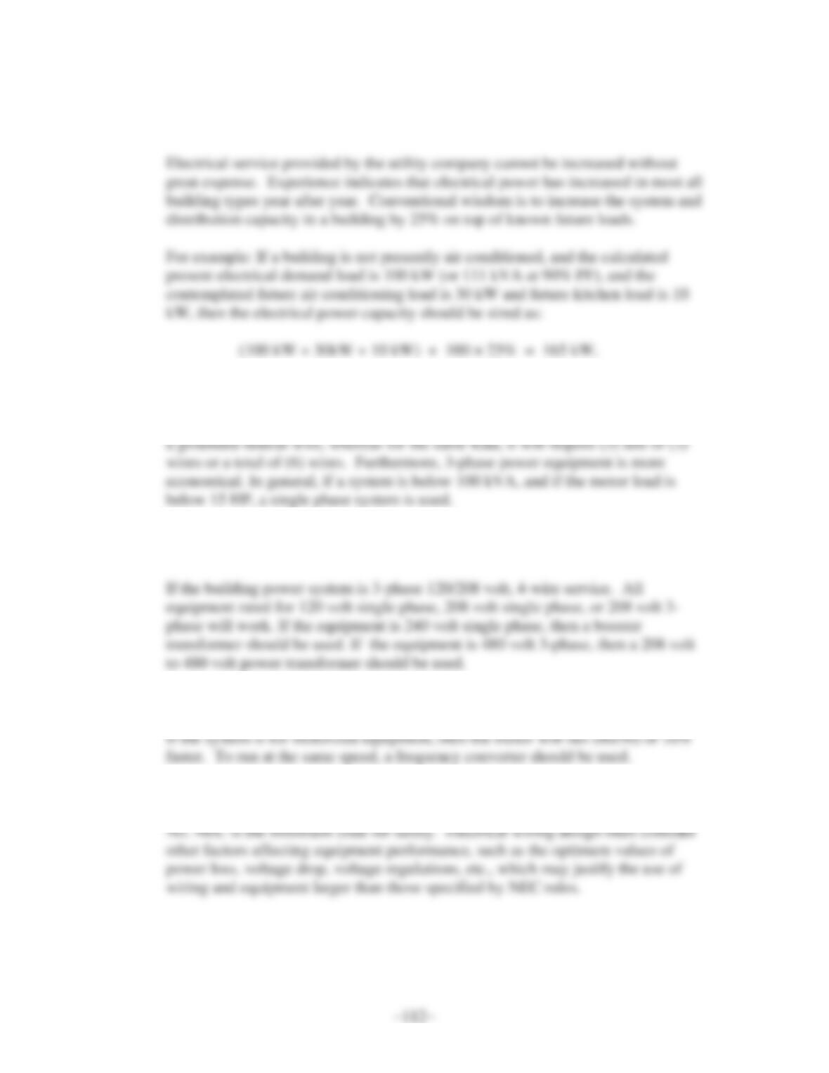
13.9 Complete the electrical floor plan for the wiring of convenience outlets in a
room as shown in the floor plan that follows. Section 13.8.1 provides the
suggested loads for general purpose outlets, which is 1.5A per outlet, or 3A
per duplex outlet. If an outlet is identified to serve a specific equipment, then
the load for that outlet shall be based on the nameplate rating of the
equipment, for example, a TV, a computer, etc. For purpose of this problem,
the load at each receptacle is identified as follows:
C – general purpose receptacle 3A
D – special equipment 5A
E – special equipment 10A
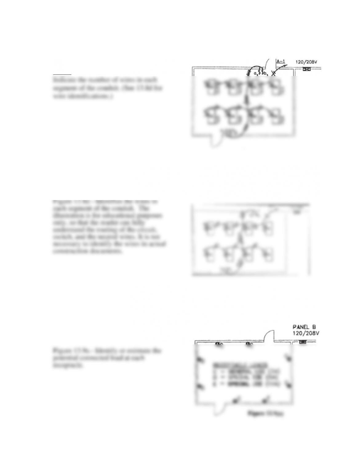
Step 2
Prepare the conduit plan indicating the
conduit connections between electrical
devices (fixtures and switches) to be
wired.
110
Step 3
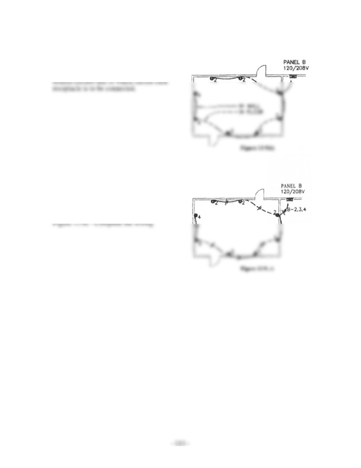
Figure 13.9 b – Determine the number of
13.10 Why is the system capacity for future loads important? What is the general
practice?
13.11 Name the advantages of a three-phase system over a single-phase system.
For the same electrical load, 3-phase delta or wye systems use (4) wires, including
13.12 What could you do if new equipment that will be installed in a building has a
different voltage rating or phase connections?
13.13 What if equipment rated for 50 Hz is connected to a 60 Hz system?
13.14 Should National Electrical Code (NEC) be followed to the letter?

13.15 What is the minimum size wire for branch circuits in residential
buildings and for institutional buildings?
13.16 If a branch circuit is rated for 30 amperes, what is the maximum rating of
portable equipment that can be connected to this circuit?
13.17 Is EMT conduit allowed for in-the-floor installations? In wet locations?
13.18 Should all three phases of a circuit be installed in the same conduit or in
different conduits?