477
Chapter 12
Solve these problems using the plate element from a computer program.
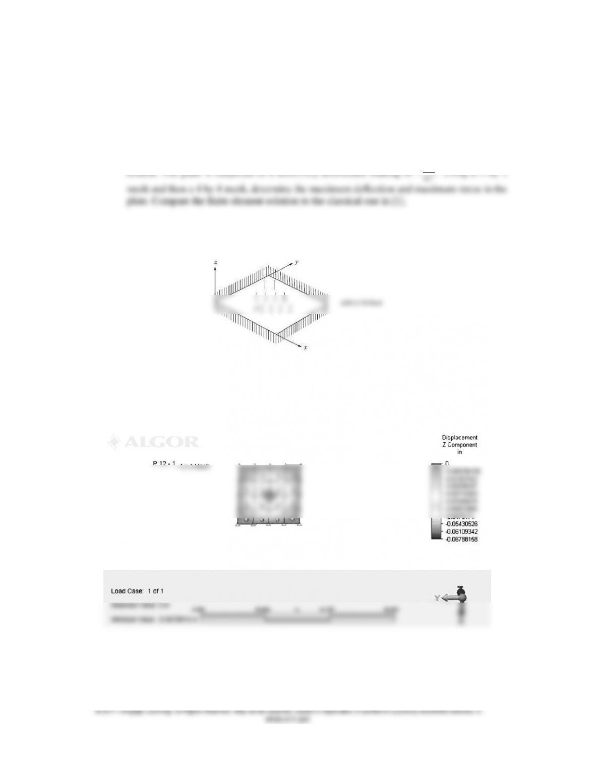
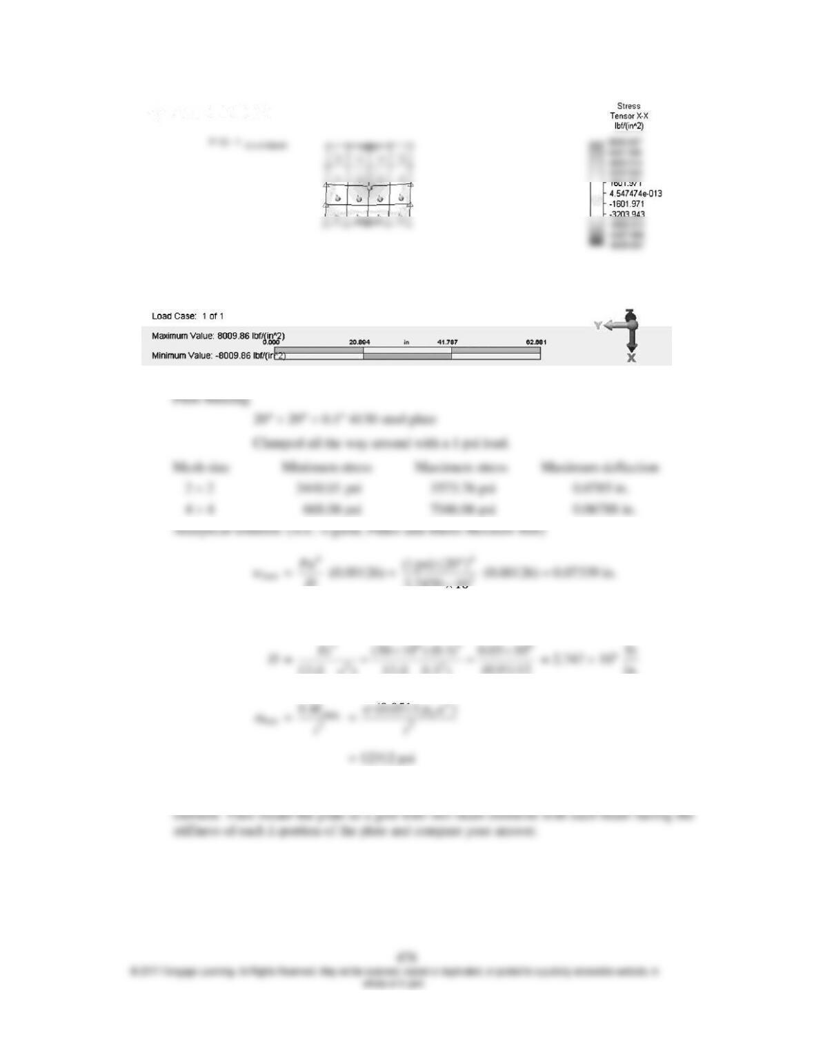
12.1 A square steel plate of dimensions 20 in. by 20 in. with thickness of 0.1 is clamped all
around. The plate is subjected to a uniformly distributed loading of 1
2
lb
in.
. Using a 2 by 2
Figure P12–1 AISI 4130 Steel
479
Figure P12–2
12.3 A square simply supported 20 in. by 20 in. steel plate with thickness 0.15 in. has a round
in.
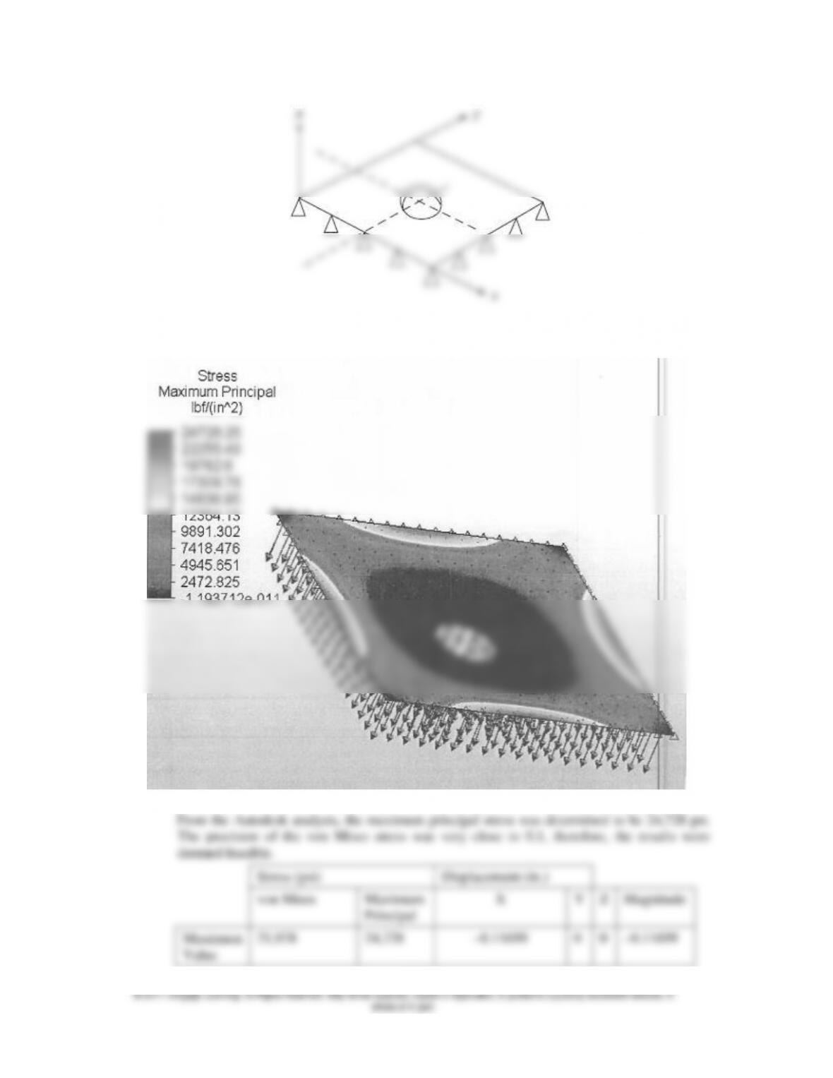
Figure P12–3
482
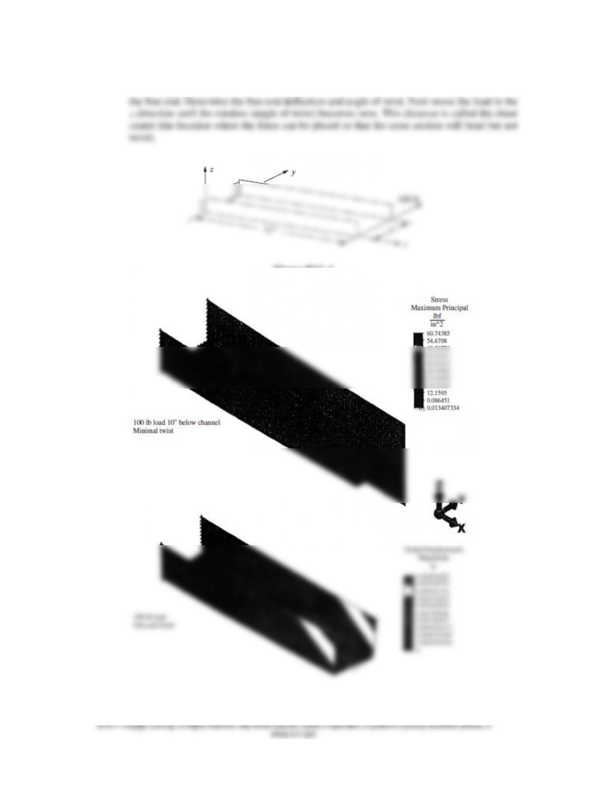
12.4 A C-channel section structural steel beam of 2 in. wide flanges, 3 in. depth and thickness of
both flanges and web of 0.25 in. is loaded as shown with 100 lb acting in the y direction on
Figure P12–4
Need to apply load at shear center. See Table 5-1, Chapter 5.
483
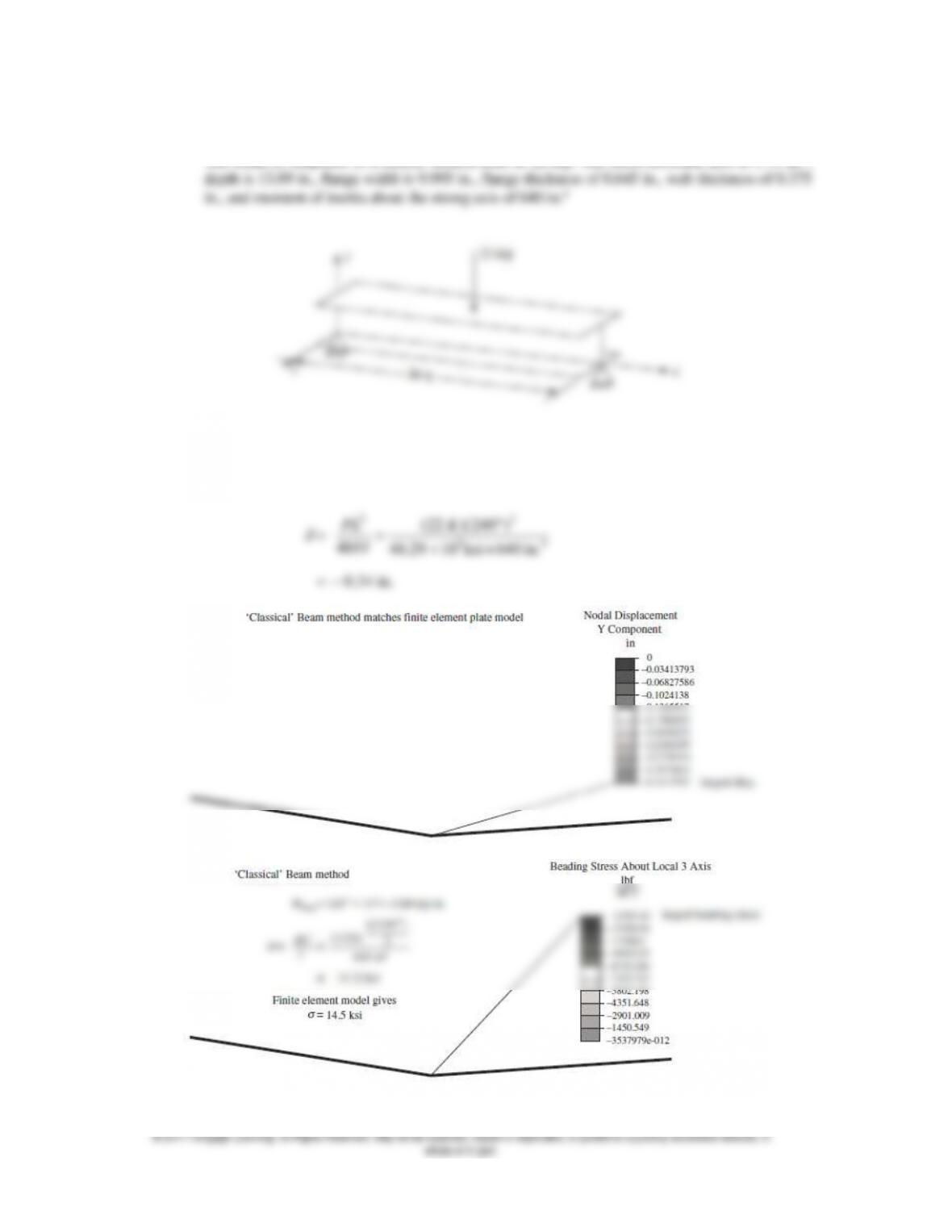
12.5 For the simply supported structural steel W 14 61 wide flange beam shown, compare the plate
element model results with the classical beam bending results for deflection and bending stress.
The beam is subjected to a central vertical load of 22 kip. The cross-sectional area is 17.9 in.2,
Figure P12–5
33
(22 )(240 )
PL K
484
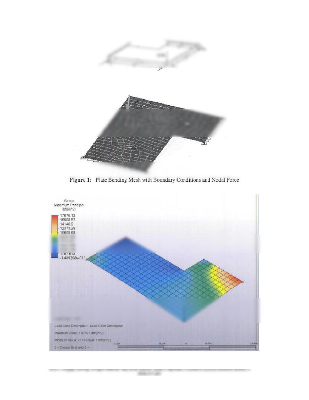
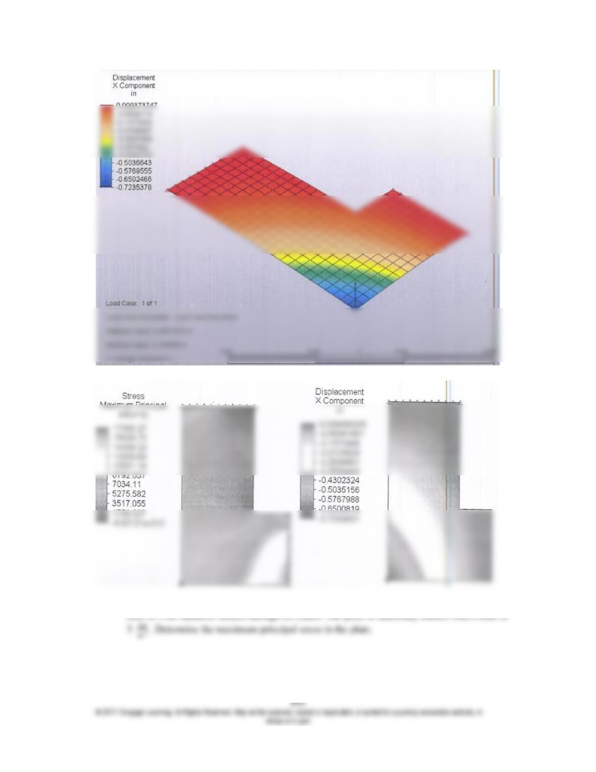
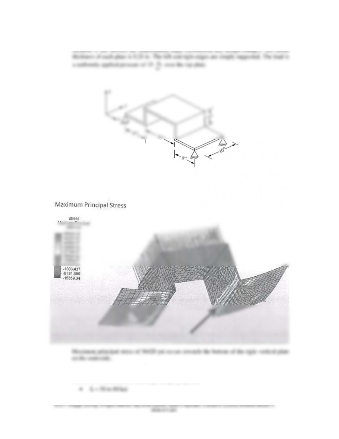
12.6 For the structural steel plate structure shown, determine the maximum principal stress and its
in.
Figure: P12–6
Maximum displacement is 0.2303 in. at center of top plate.
ASTM A-36 steel has the following strength properties.
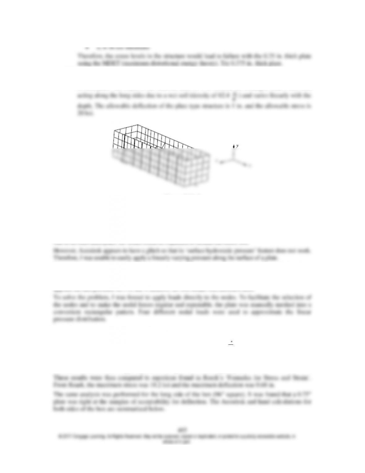
12.7 Design a steel box structure 4 ft wide by 8 ft long made of plates to be used to protect
construction workers while working in a trench. That is, determine a recommended thickness
of each plate. The depth of the structure must be 8 ft. Assume the loading is from a side load
lb
Figure P12–7
Solution method
I first attempted to solve the problem by examining the long side and short side of the box individually,
rather than as a welded assembly. It was felt that once believable results were obtained from modeling each
side as an individual plate, the model could be expanded to include the entire box.
To get around this problem, I tried to break the side plate of the box into 4 vertically stacked sections
(different Autodesk parts) and then applying a different pressure to the surface of each section so that
it approximated the linear pressure distribution of the soil. However, Autodesk failed to recognize the
applied surface pressure on 3 of the 4 sections. So this model was deficient also.
Results
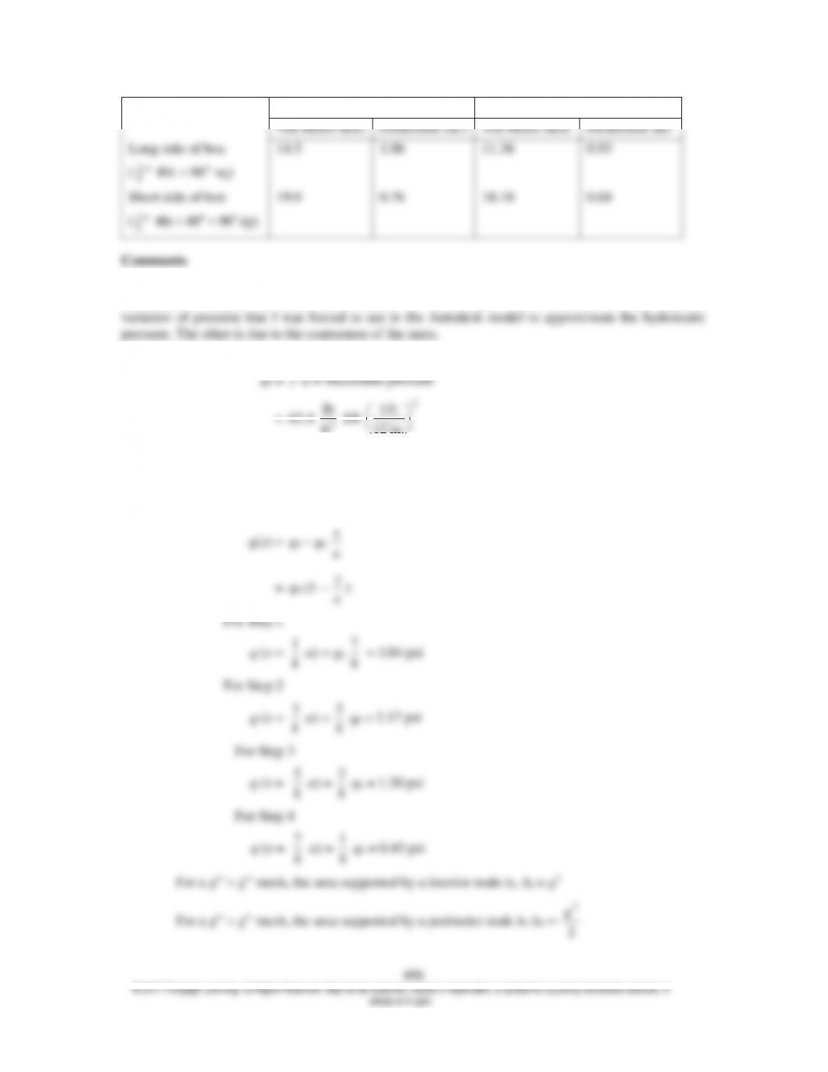
For the short side of the box (48 wide 96 deep), it was found that a
3
8
thick plate was as thin as could
be used and still meet the given design criteria. Using simply supported boundary conditions, the maximum
von Mises stress was 19.9 ksi and the maximum deflection was 0.76. The maximum stress was located at
the bottom corners, which is typically an area of high stress for rectangular plates.
Autodesk model
Hand Calc.
von Mises (ksi)
Deflection (in.)
von Mises (ksi)
Deflection (m)
Long side of box
(
3
4
thk 96 sq)
14.5
1.06
11.36
0.93
Short side of box
(
3
8
thk 48 96 dp)
19.9
0.76
18.18
0.68
Comments
For both sides, the Autodesk model predicted higher stress and higher deflection than the hand
calculations. I suspect the difference in results can be attributed to two sources. One, the stepwise
Nodal loads to approximate hyprostatic pressure variation as function of depth
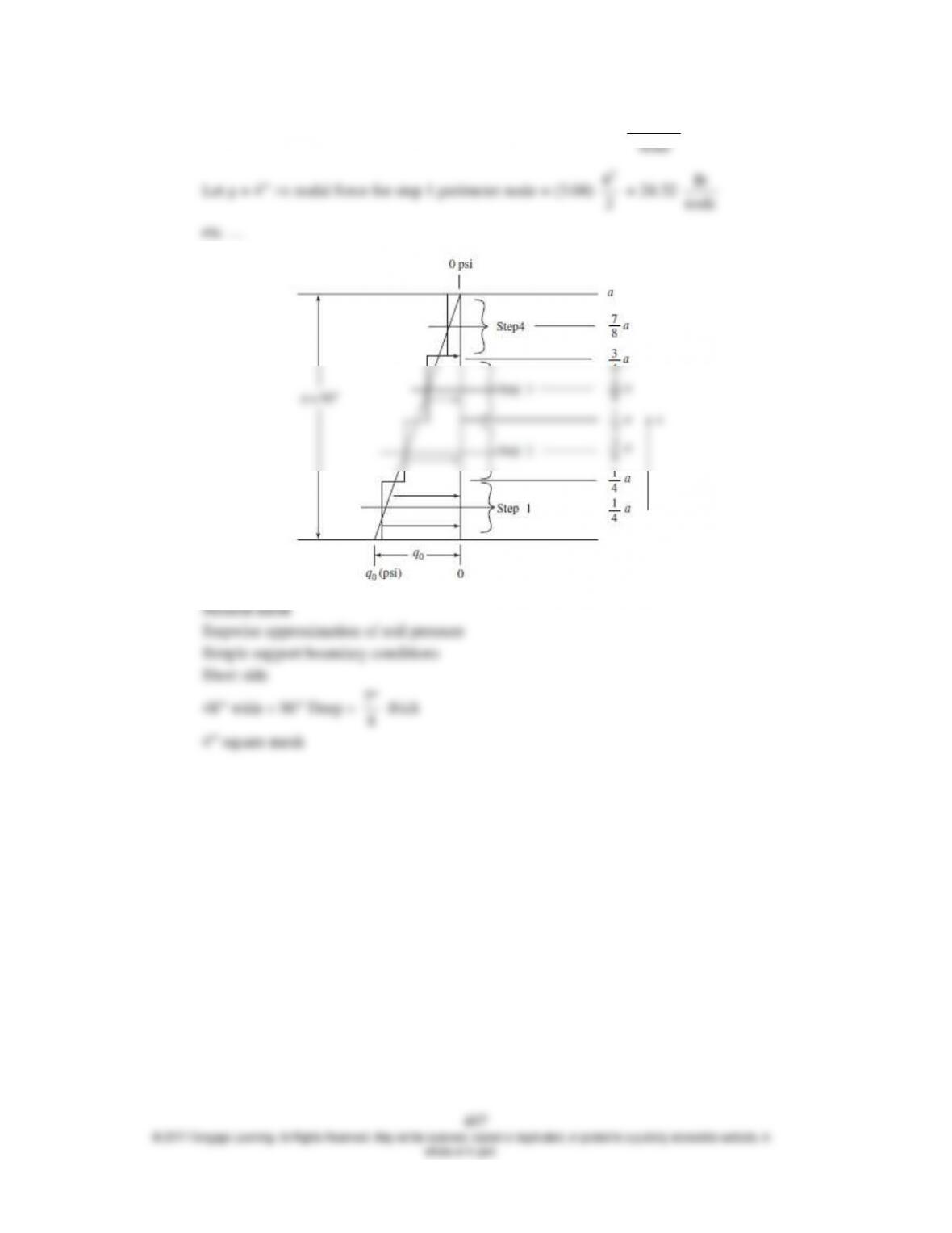
Let g = 4 nodal force for step 1 interior node = (3.04) (4)2 =
48.64 lb
node
2
4
lb