u = a1 + a2 x + a3 y + a4 z
11.11
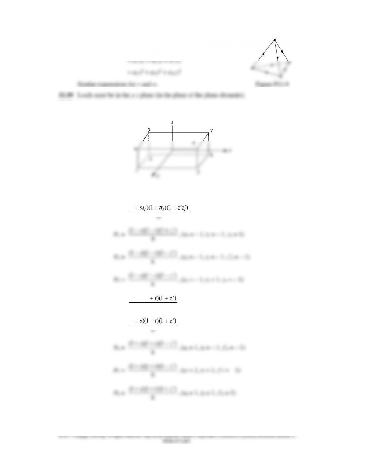
Using Equation (11.3.3) and Figure 11.5
Ni =
(1 )(1 )(1 )
8
i i i
ss tt z z
(1 – )(1 – )(1 – )
s t z
(1 – )(1 – )(1 )
s t z
8
(1 – )(1 )(1 – )
s t z
8
N4 =
(1 – )(1 )(1 )
8
s t z
, (s4 = – 1, t4 = 1, z4 = 1)
N5 =
(1 )(1 – )(1 )
8
s t z
, (s5 = 1, t5 = – 1, z5 = 1)
8
(1 )(1 )(1 – )
s t z
(1 )(1 )(1 – )
s t z
8
8
s t z
8
(1 )(1 )(1 )
i i i
ss tt z z
N2 =
(1 )(1 )(1 )
8
s t z
(– s – t – z – 2)
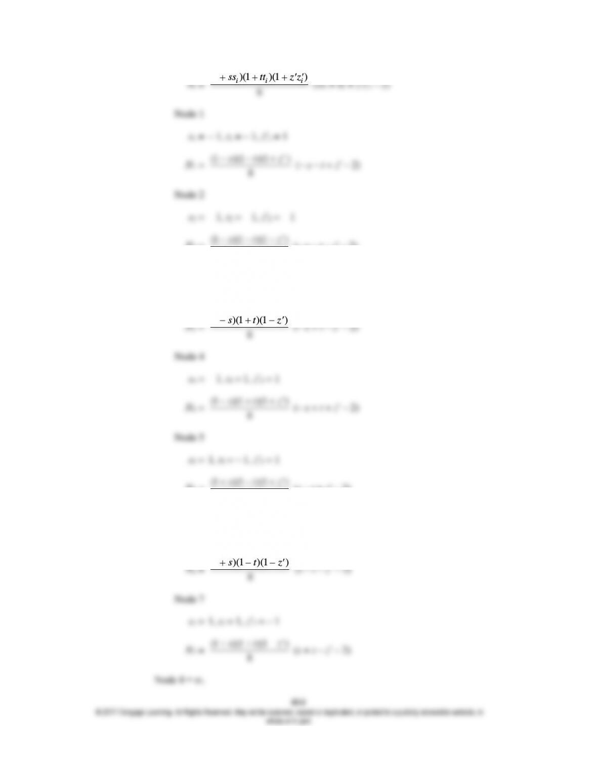
Node 3
s3 = – 1, t3 = 1, z3 = – 1
(1 )(1 )(1 )
(1 )(1 )(1 )
s t z
s t z
8
N5 =
(1 )(1 )(1 )
8
s t z
(s – t + z – 2)
Node 6
s6 = 1, t6 = – 1, z6 = – 1
(1 )(1 )(1 )
s t z
8
11.14
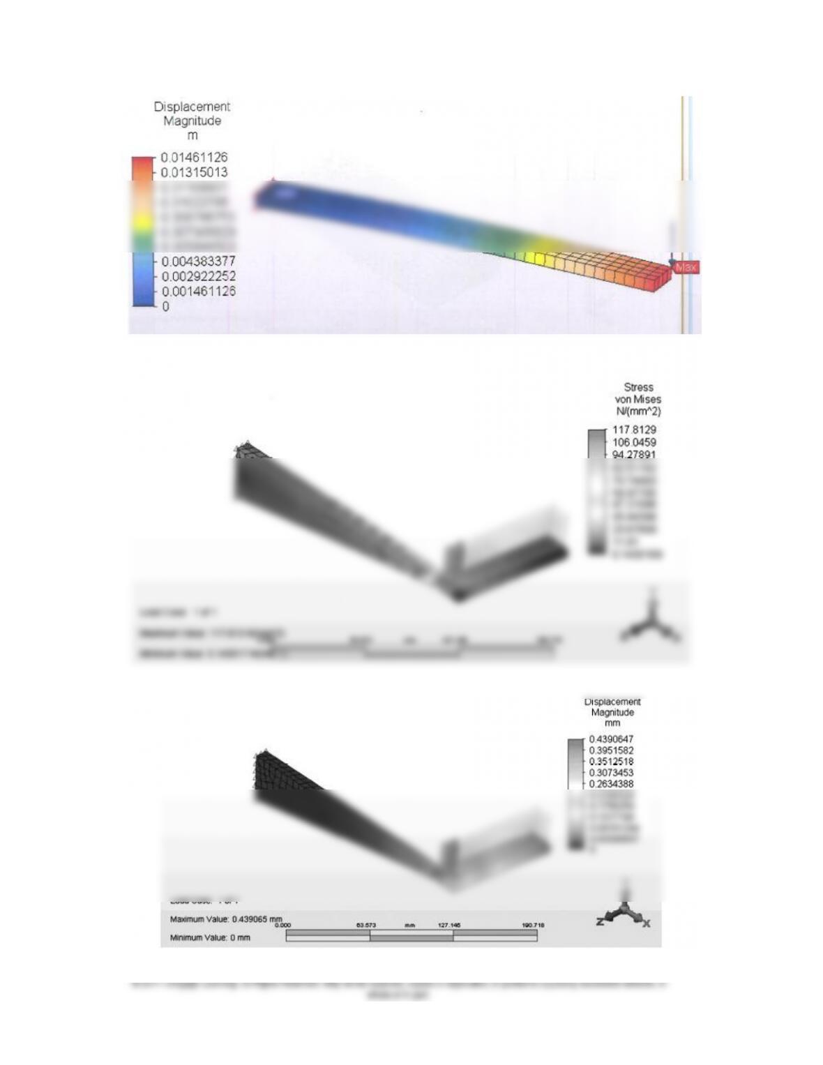
466
11.15 (Load replaced with concentrated end load)
11.16
11.17
11.18
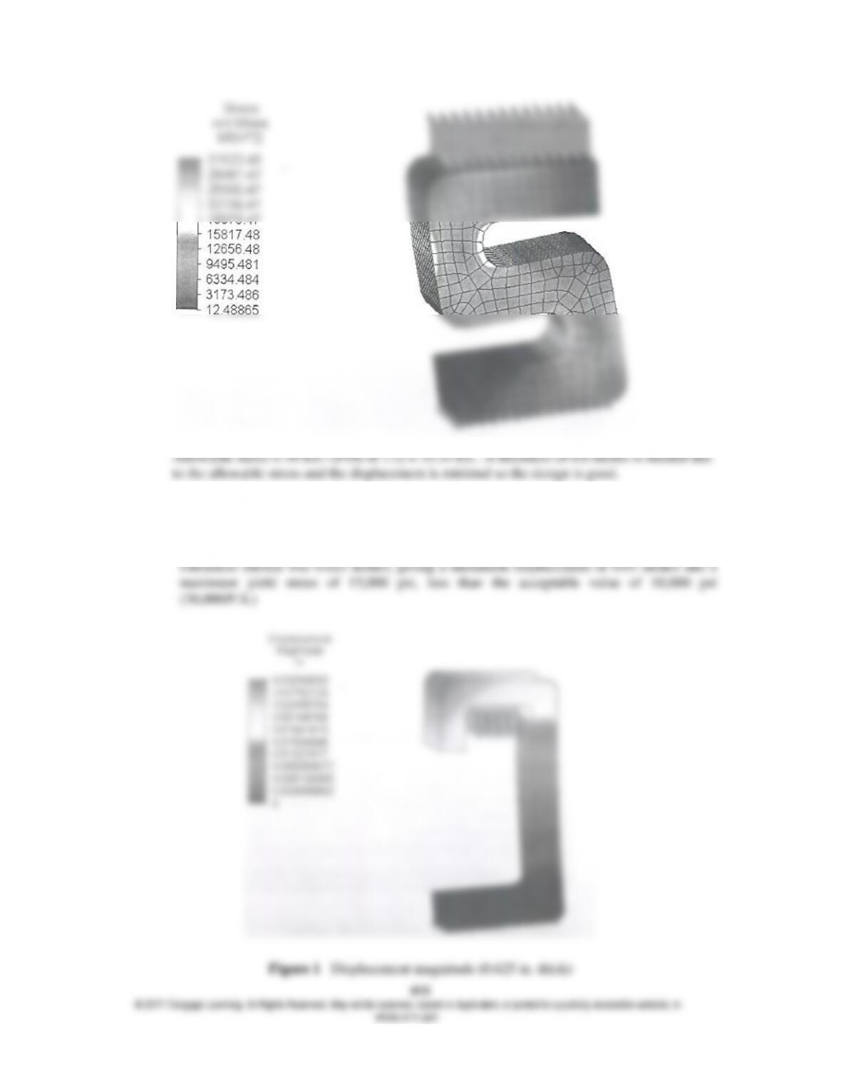
Determine the thickness of the device such that the maximum deflection is 0.1 in. vertically.
469
Figure 2 von Mises Stress Distribution (0.625 in. thick)
11.19
Model Variables
Variable
Value
Material
1035 quenched & tempered steel
Modulus of Elasticity
200 MPa
Force
150 N
Yield Strength
615 MPa
Maximum von Mises Stress
758 MPa
Maximum Displacement
4.13 mm
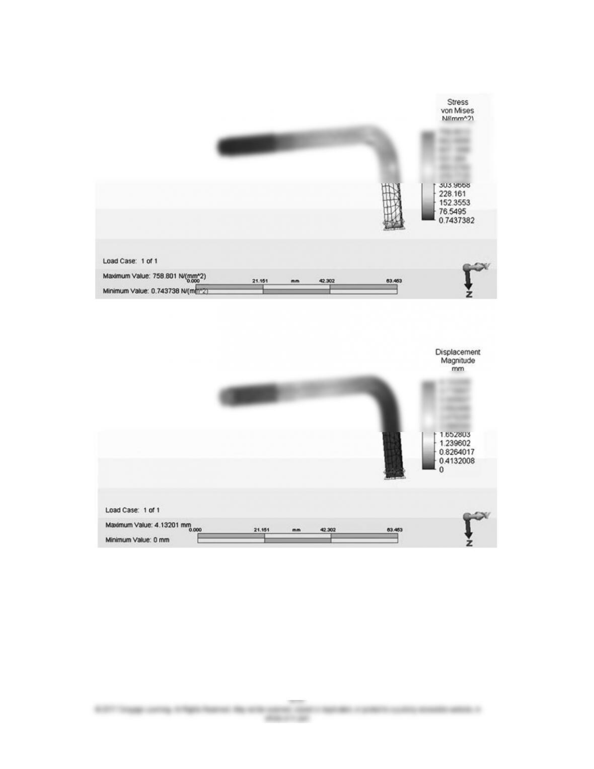
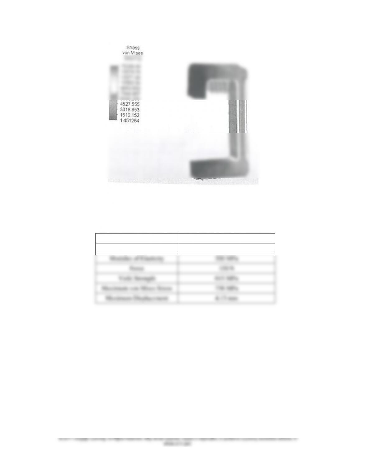
Autodesk Results
Figure 1 von Mises Stress (MPa)
Figure 2 Displacement (mm)
11.20
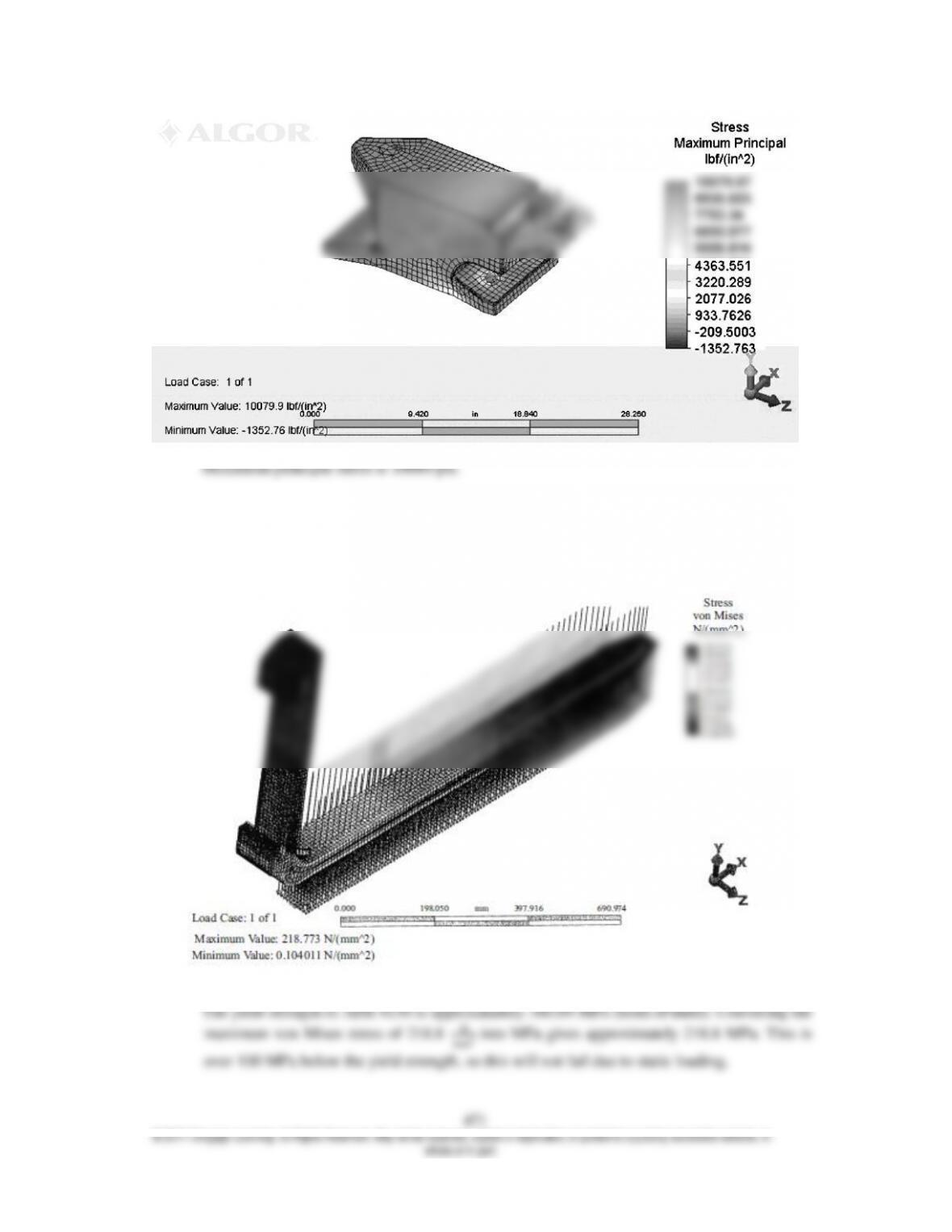
11.21
von Mises Stress
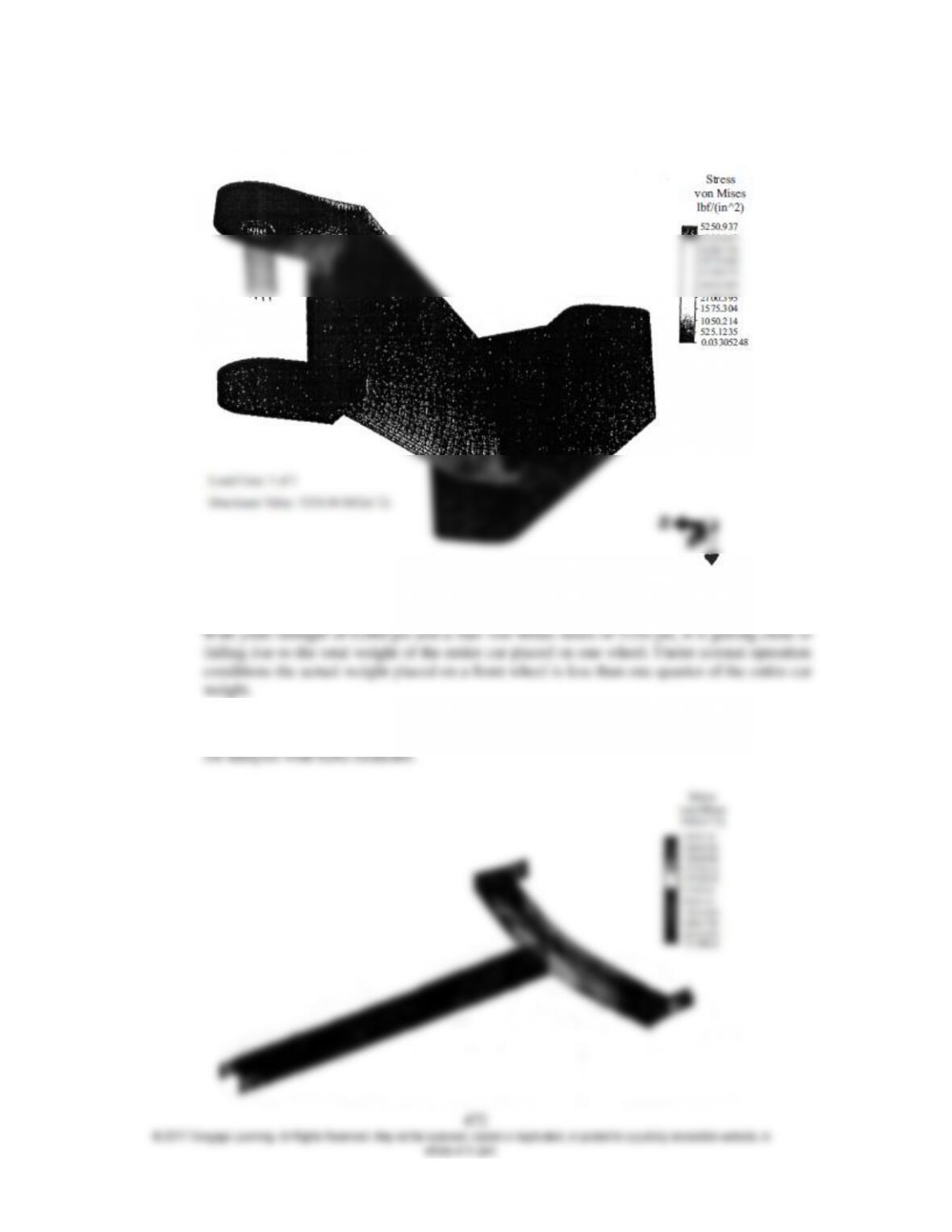
11.22
Figure 1 von Mises Stress of part.
11.23
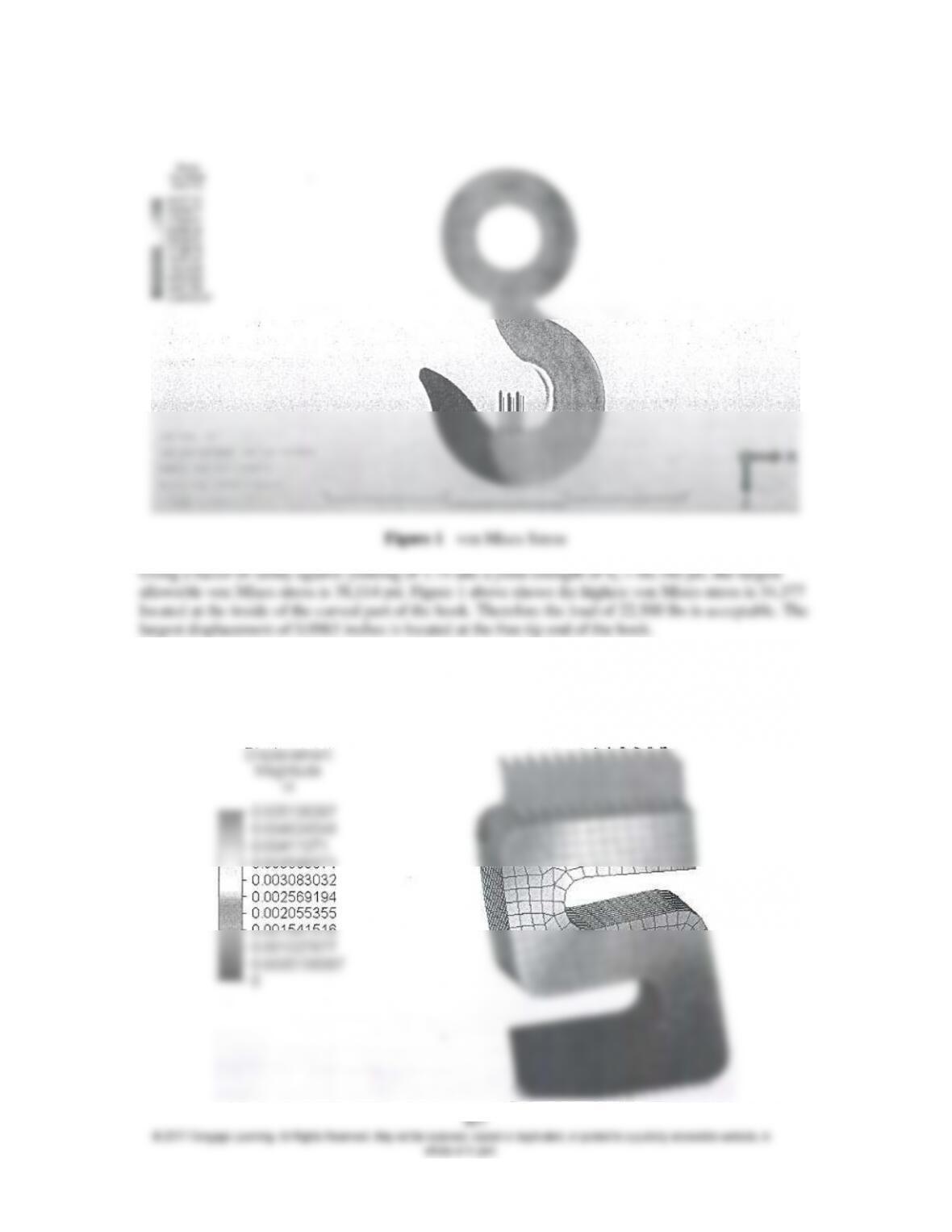
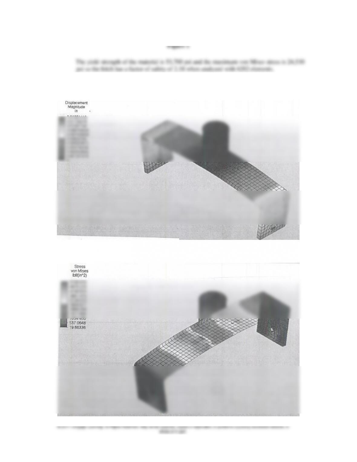
With 6,282 elements Algor calculates higher stresses. Figure 1 shows the von Mises stress
473
11.24
Maximum deflection = 0.01251 inches
11.25
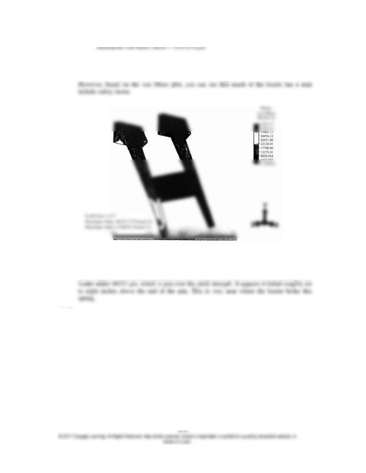
The von Mises plot of the loader under loading is shown below in Figure 1. I am looking for
the load that caused the loader to break. For this to happen, there is no factor of safety,
Figure 1 von Mises Plot
I found that a load of 2200 pounds applied on three sides of the right lower arm (left in the
above figure) in a counter clockwise direction caused the loader to fail. This loader put the
11.26
11.28