Problem 10.31 Model the ladder rung as a simply
supported (pin-supported) beam and assume that the
750-N load exerted by the person’s shoe is uniformly
distributed. Draw the shear force and bending moment
diagrams.
200 mm 100 mm
375 mm
x
y
Problem 10.32 What is the maximum bending moment
in the ladder rung in Problem 10.31 and where does it
occur?
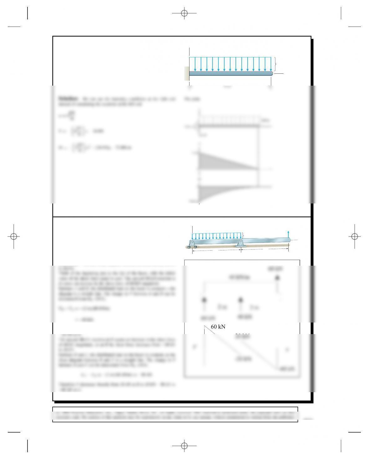
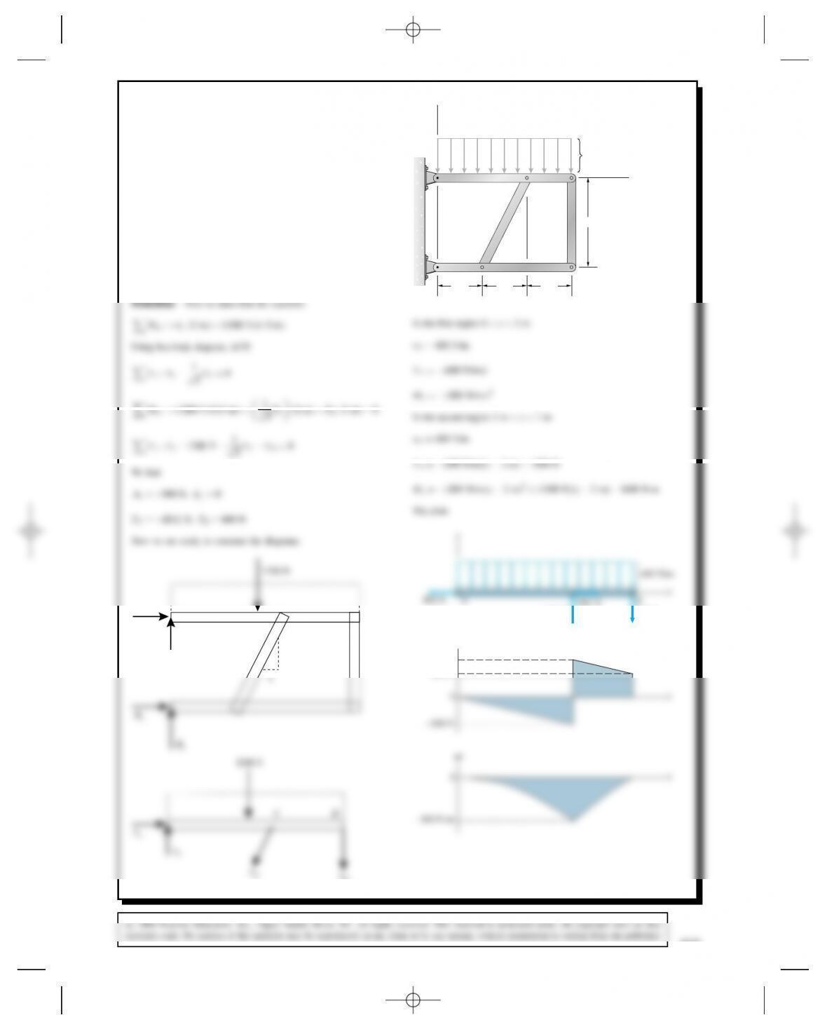
Problem 10.33 Assume that the surface the beam rests
on exerts a uniformly distributed load. Draw the shear
force and bending moment diagrams.
4 kN
6 m
2 m 1 m
2 kN
y
x
810
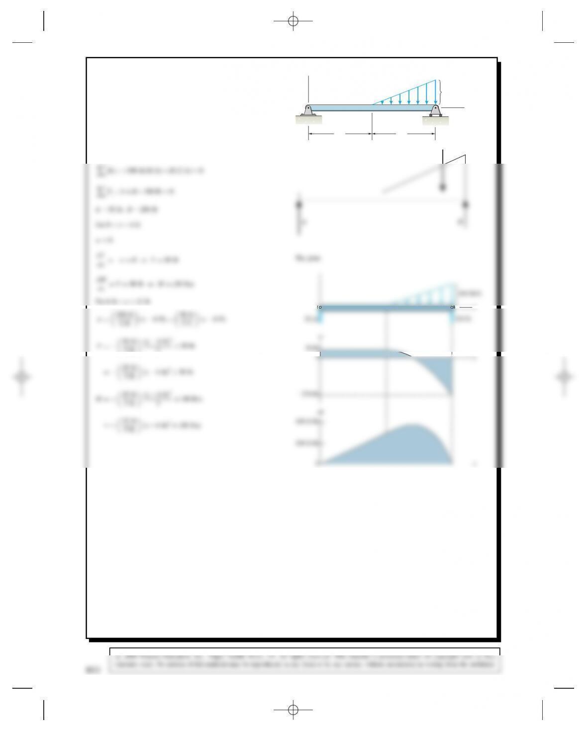
Problem 10.34 The homogeneous beams AB and CD
weigh 600 lb and 500 lb, respectively. Draw the shear
force and bending moment diagrams for beam AB.
200 lb 2 ft
6 ft
B
C
D
A
ft xx
2CMD0
ft ⊲6ftx⊳2
2B⊲6ftx⊳ D0
M
x
0
Problem 10.35 Draw the shear force and bending
moment diagrams for beam CD in Problem 10.34.
Solution: Use the reactions from 10.34
100 lb/ft x
V
C
100 lb/ft x
B
C
V
y
812
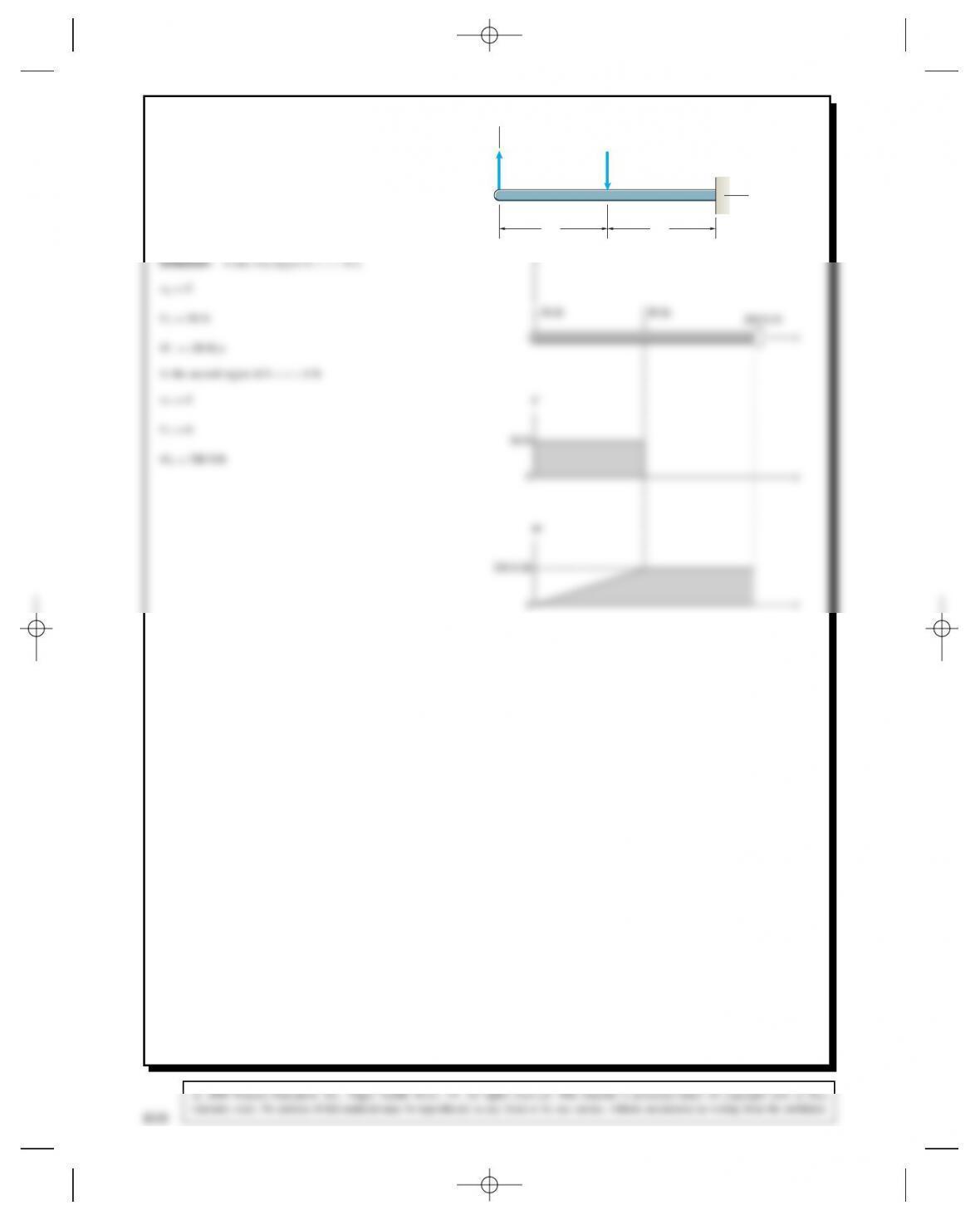
Problem 10.36 Determine the shear force Vand bending
moment Mfor the beam as functions of xfor 0 <x<
3 ft.
600 lb/ft
x
y
600 lb/ft
Problem 10.37 Draw the shear force and bending
moment diagrams for the beam.
3 ft
600 lb/ft
3 ft
x
y
600 lb/ft
814
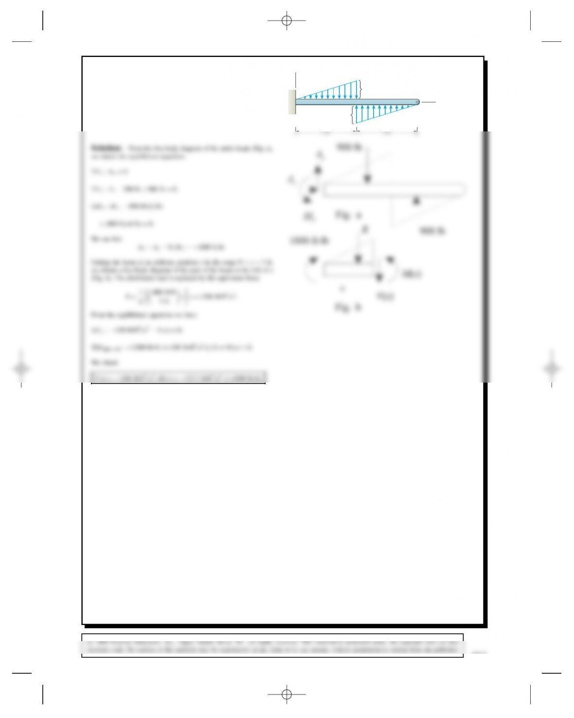
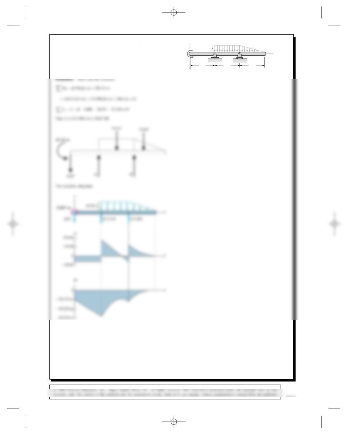
Problem 10.38 In preliminary design studies, the
vertical forces on an airplane’s wing are modeled as
shown. The distributed load models aerodynamic forces
and the force exerted by the wing’s weight. The 80-kN
force at xD4.4 m models the force exerted by the
weight of the engine. Draw the shear force and bending
moment diagrams for the wing for 0 <x<4.4m.
y
x
50 kN/m
80 kN
4.4 m 13.0 m
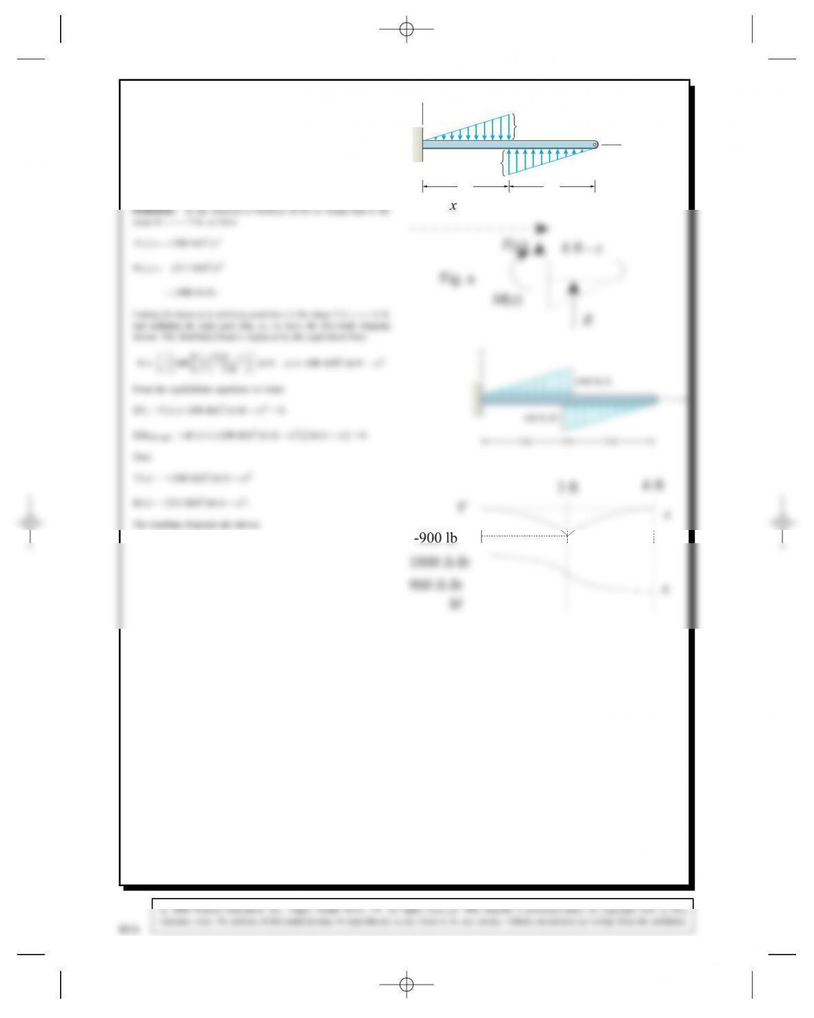
Solution: From the free-body diagram of the entire wing (Fig. a),
we obtain the equilibrium equations
Fx:AxD0,
V⊲x⊳ D⊲50 kN/m⊳x 465 kN,
x
⫺245 kN
⫺465 kN
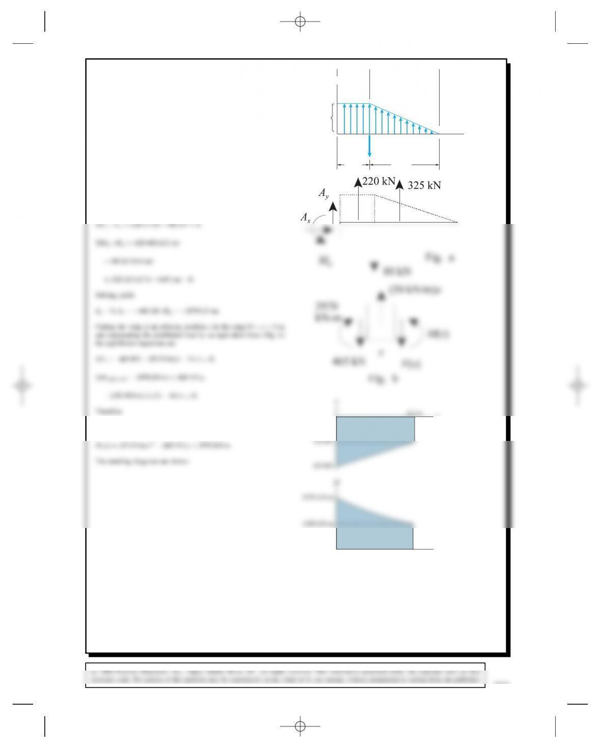
Problem 10.39 Draw the shear force and bending
moment diagram for the entire wing. y
x
50 kN/m
80 kN
4.4 m 13.0 m
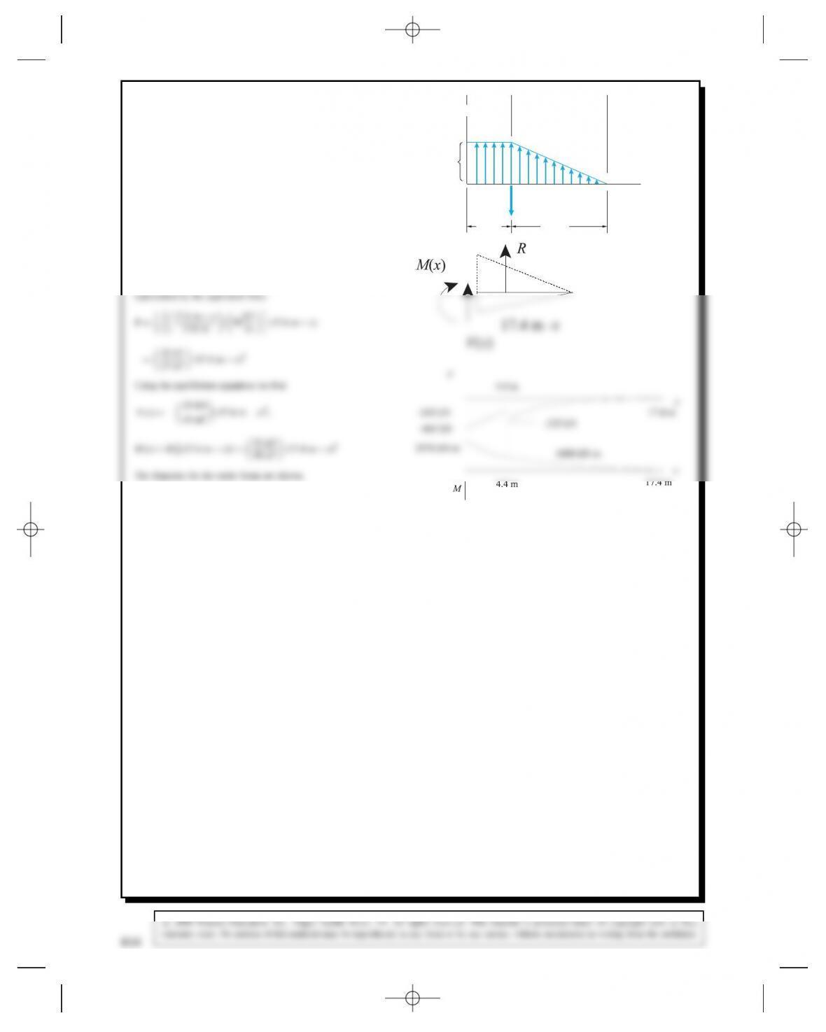
Solution: The shear force and bending moment diagrams for 0 <
x<4.4 m were obtained in the solution to Problem 10.38. Cut the
wing at an arbitrary position xin the range 4.4 m <x<17.4 m and
isolate the right part of the beam (Fig. a). The distributed loading is
816
Problem 10.40* Draw the shear force and bending
moment diagrams.
x
y
6 m
20 kN-m
6 m 6 m
6 kN
4 kN/m
Problem 10.41 Draw the shear force and bending
moment diagrams.
4 ft
50 lb 50 lb
4 ft
y
x
818
Problem 10.42 Draw the shear force and bending
moment diagrams.
3600 N-m
x
y
2 m 4 m
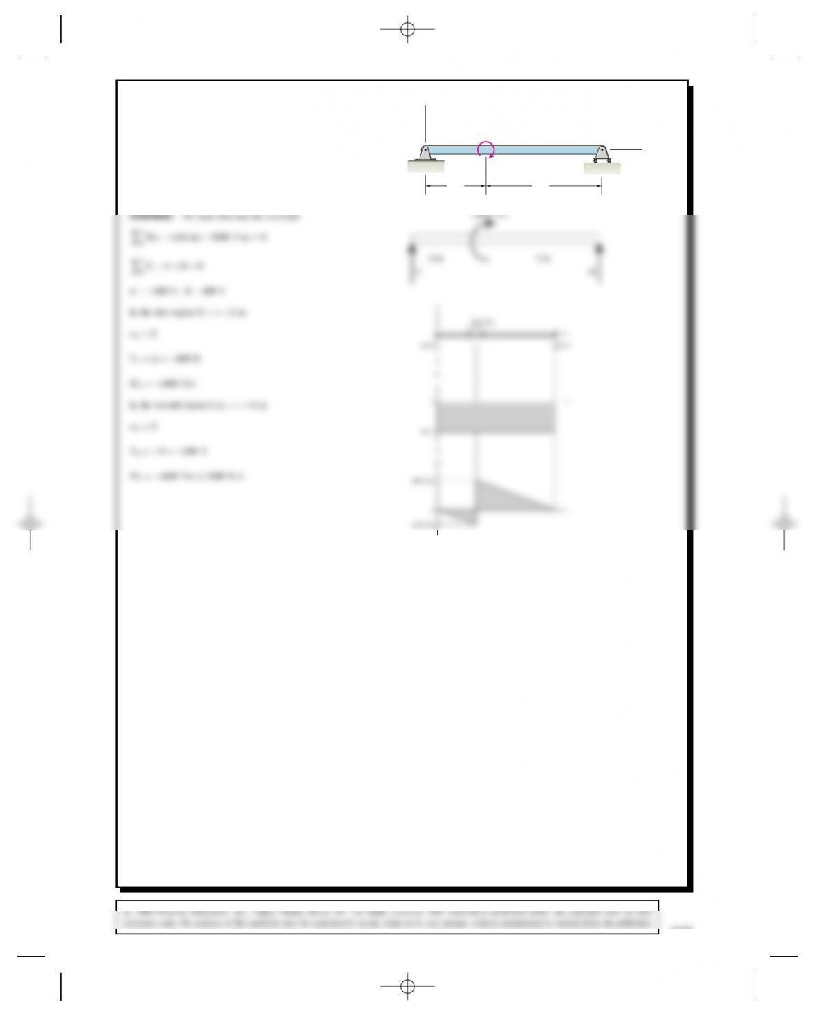
Problem 10.43 This arrangement is used to subject a
segment of a beam to a uniform bending moment. Draw
the shear force and bending moment diagrams.
50 lb 50 lb
x
y
6 in 6 in
12 in
820
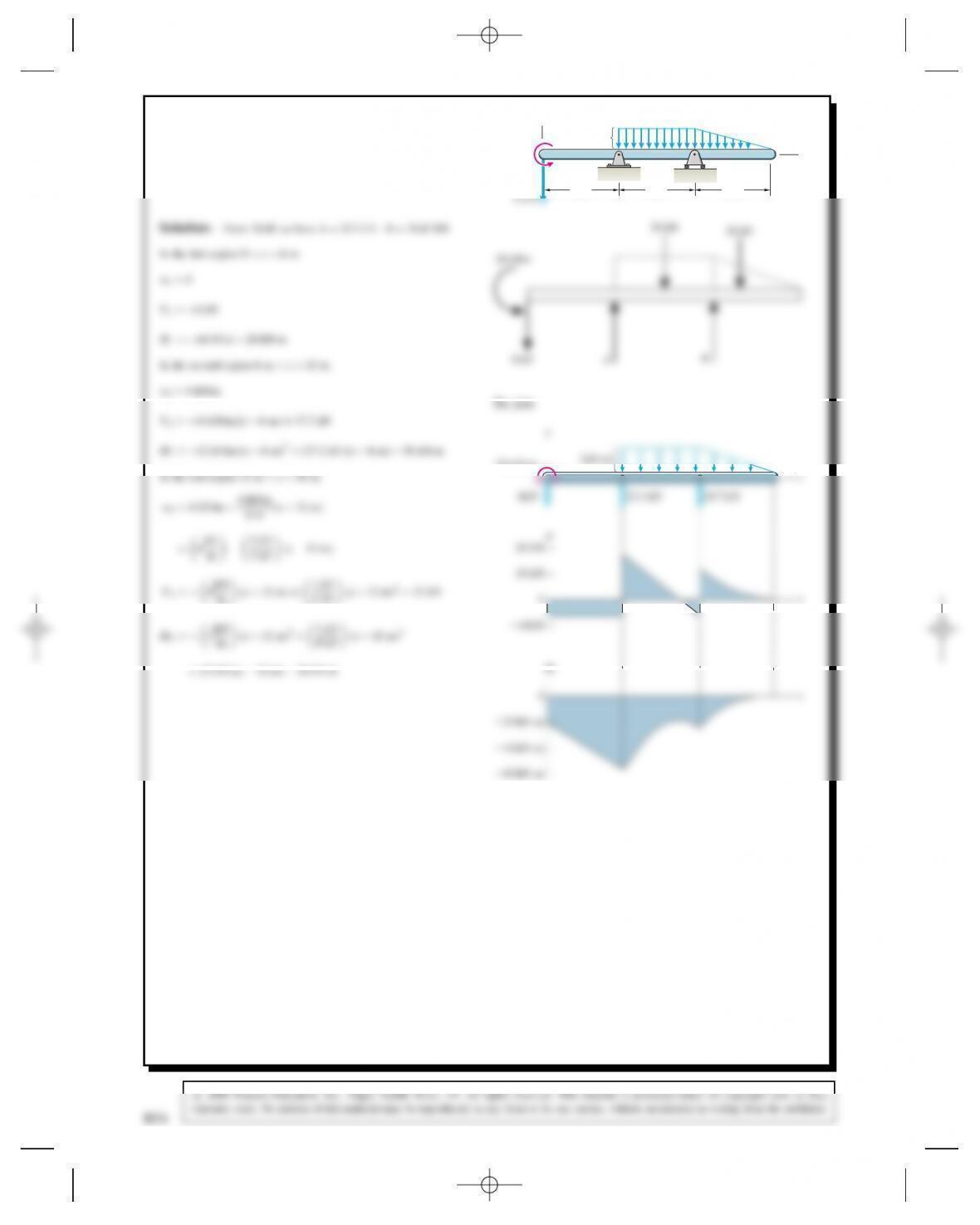
Problem 10.44 Use the procedure described in
Example 10.5 to draw the shear force and bending
moment diagrams for the beam.
4 kN/m
y
x
MD2kN
mx2C⊲24 kN⊳x 72 kN-m
x
x
24 kN
0
0
⫺72 kN-m
M
Problem 10.45 In Active Example 10.4, suppose that
the 40 kN/m distributed load extends all the way across
the beam from Ato C. Draw a sketch of the beam with
its new loading. Draw the shear force diagram for the
beam.
y
x
40 kN/m
2 m
A
60 kN
BC
2 m
Solution: The free-body diagram with the reactions already solved
Therefore Vdecreases linearly from 60 kN at Ato 60 kN 80 kN D
Problem 10.46 Draw the shear force and bending
moment diagrams.
100 lb/ft
x
y
6 ft 6 ft
Solution: Find the reactions first
300 lb
822
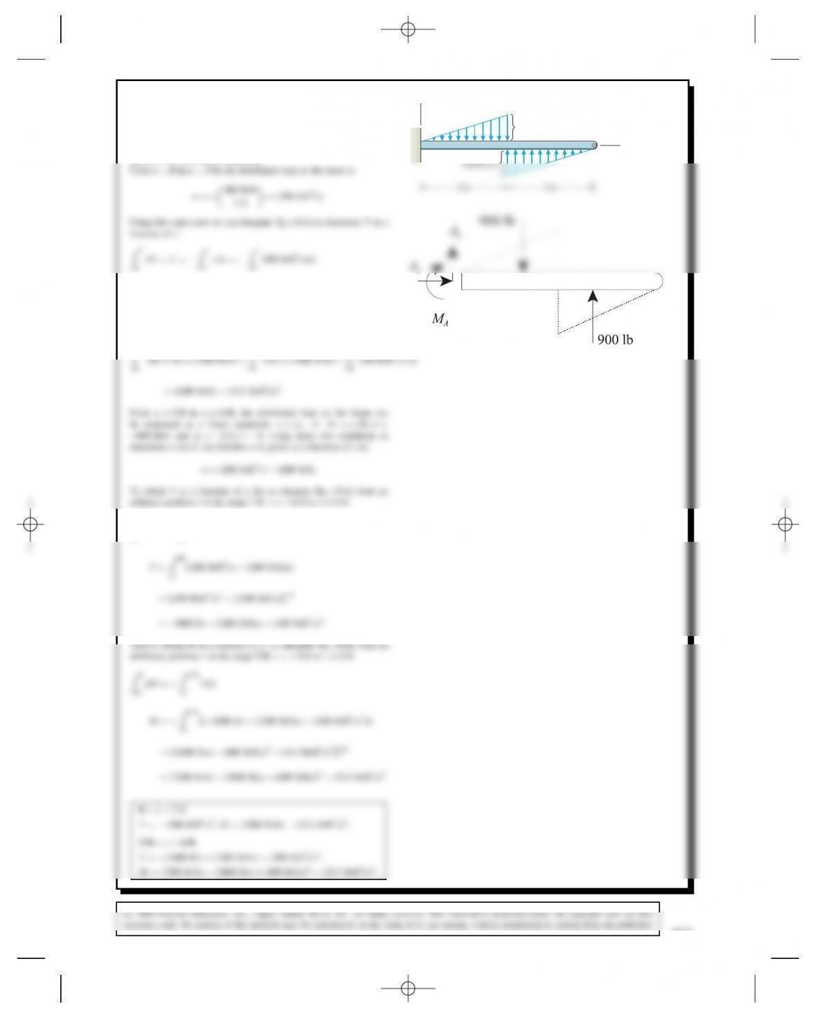
Problem 10.47 Determine the shear force Vand
bending moment Mfor the beam as functions of x.
600 lb/ft
x
y
Solution: From the free-body diagram of the entire beam we learn
that AxDAyD0,M
AD1800 ft-lb.
0
0
0
D⊲100 lb/ft2⊳x2.
The clockwise couple at xD0 causes an increase in the bending
moment of 1800 ft-lb. We can integrate Eq. (10.6) to determine M
as a function of x.
M
dM DMD⊲1800 ft-lb⊳Cx
Vdx D⊲1800 ft-lb⊳x
⊲100 lb/ft2⊳x2dx
0
V
dV D6ft
x
wdx
Problem 10.48* Draw the shear force and bending
moment diagrams.
x
y
6 m
20 kN-m
6 m 6 m
4 kN/m
M2D⊲2 kN/m⊳⊲x 6m⊳2C⊲17.2kN⊳⊲x 6m⊳56 kN-m
In the last region 12 m <x<18 m
20 kN-m
4kN/m
x
824
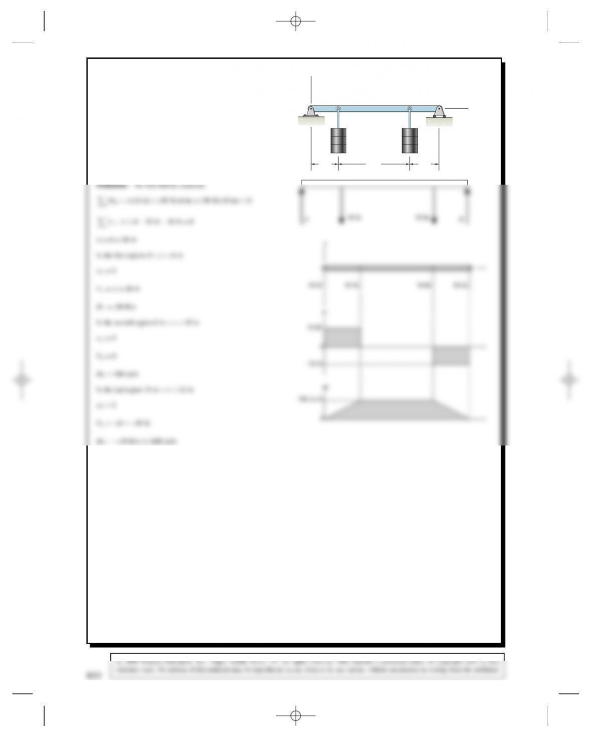
Problem 10.49 Draw the shear force and bending
moment diagrams for the beam AB.
1 m
400 N/m
1 m 1 m
2 m
AB
y
x
Ay
By
Bx
Ax
1
1200 N
2
400 N/m
600 N
1800 N
1000 N
600 N
0
⫺800 N
x
x
V
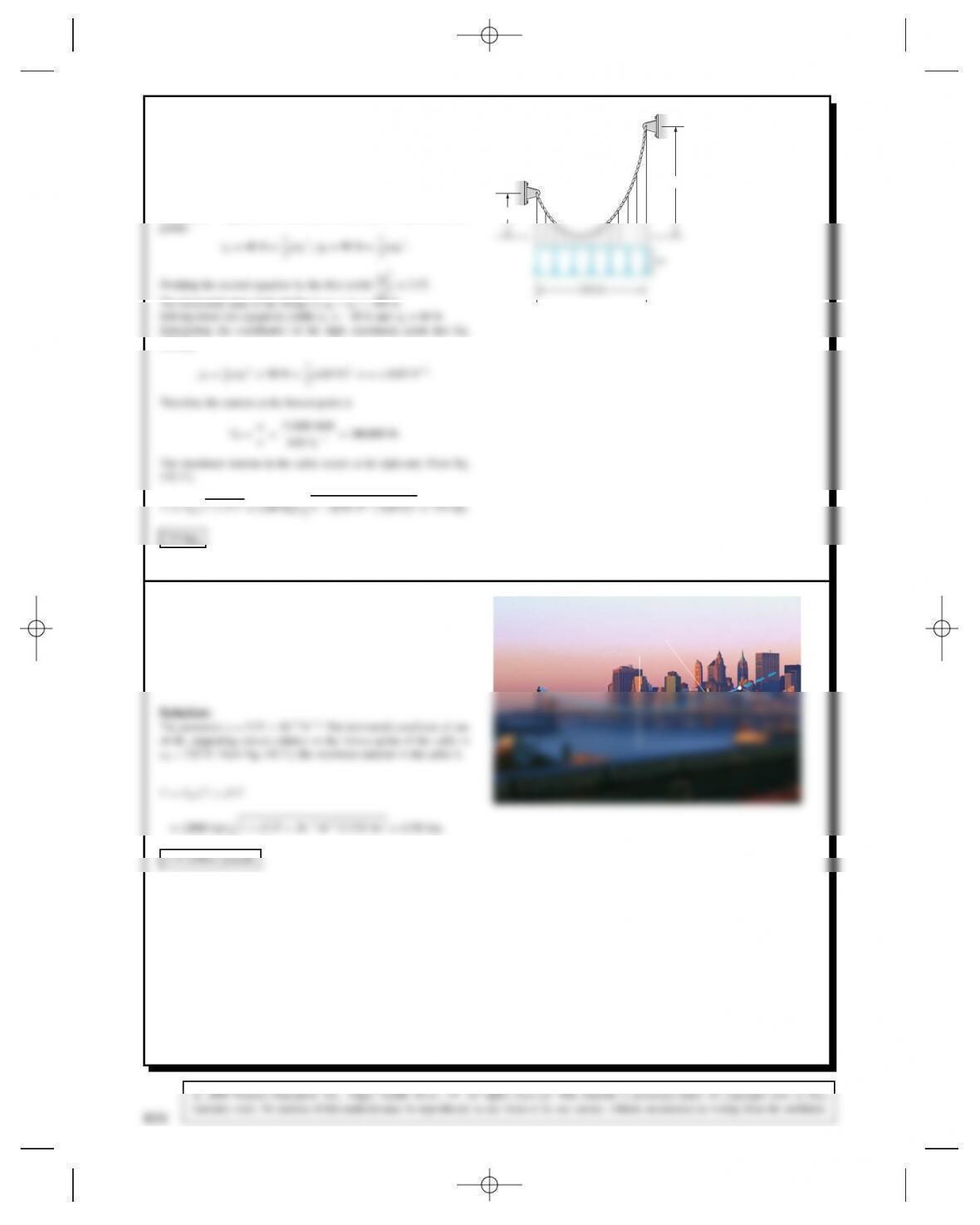
Problem 10.50 The cable supports a distributed load
wD12,000 lb/ft. Using the approach described in Active
Example 10.6, determine the maximum tension in the
cable.
40 ft
90 ft
Solution: Equation (10.10) must be satisfied for both attachment
(10.10),
Problem 10.51 In Example 10.7, suppose that the
tension at the lowest point of one of the main supporting
cables of the bridge is two million pounds? What is the
maximum tension in the cable?
yy ⫽ (2.68 ⫻ 10–4)x2
826
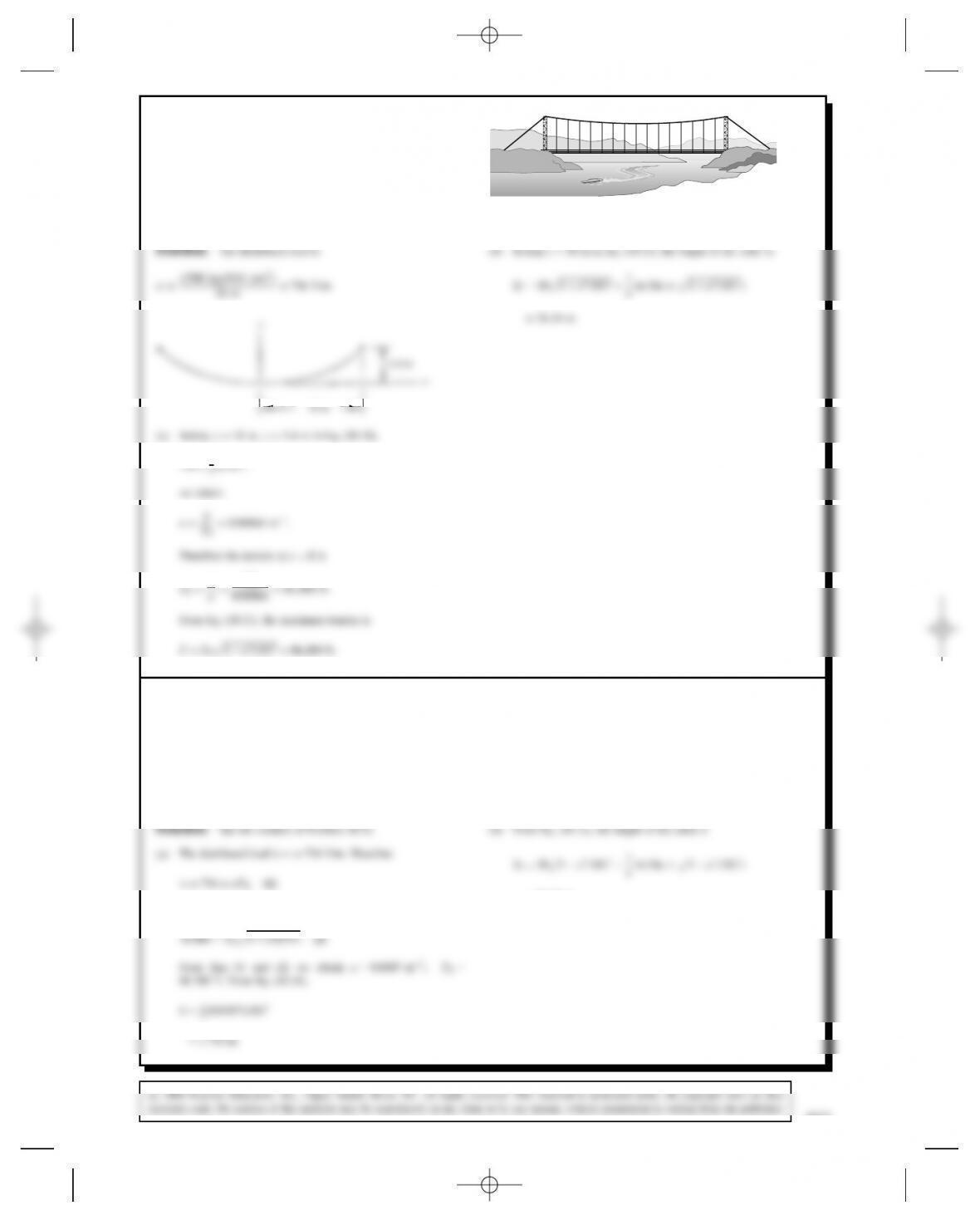
Problem 10.52 A cable is used to suspend a pipeline
above a river. The towers supporting the cable are 36 m
apart. The lowest point of the cable is 1.4 m below the
tops of the towers. The mass of the suspended pipe is
2700 kg.
(a) What is the maximum tension in the cable?
(b) What is the suspending cable’s length?
y
18 m
1.4 m
x
(a) Setting xD18 m, yD1.4 m in Eq. (10.10),
1.4D1
2a⊲18⊳2,
we obtain
aDw
T0D0.00864 m1.
Therefore the tension at xD0is
T0Dw
aD736
0.00864 D85,100 N.
From Eq. (10.11), the maximum tension is
TDT01Ca2⊲18⊳2D86,200 N.
Problem 10.53 In Problem 10.52, let the lowest point
of the cable be a distance hbelow the tops of the towers
supporting the cable.
(a) If the cable will safely support a tension of 70 kN,
what is the minimum safe value of h?
(b) If hhas the value determined in part (a), what is
the suspending cable’s length?
And setting xD18 m and TD70,000 N in Eq. (10.11),
70,000 DT01C⊲18⊳2a2.(2)
From Eqs. (1) and (2) we obtain aD0.0107 m1,T0D
68,700 N. From Eq. (10.10),
hD1
2⊲0.0107⊳⊲18⊳2
D1.734 m.
D36.22 m.
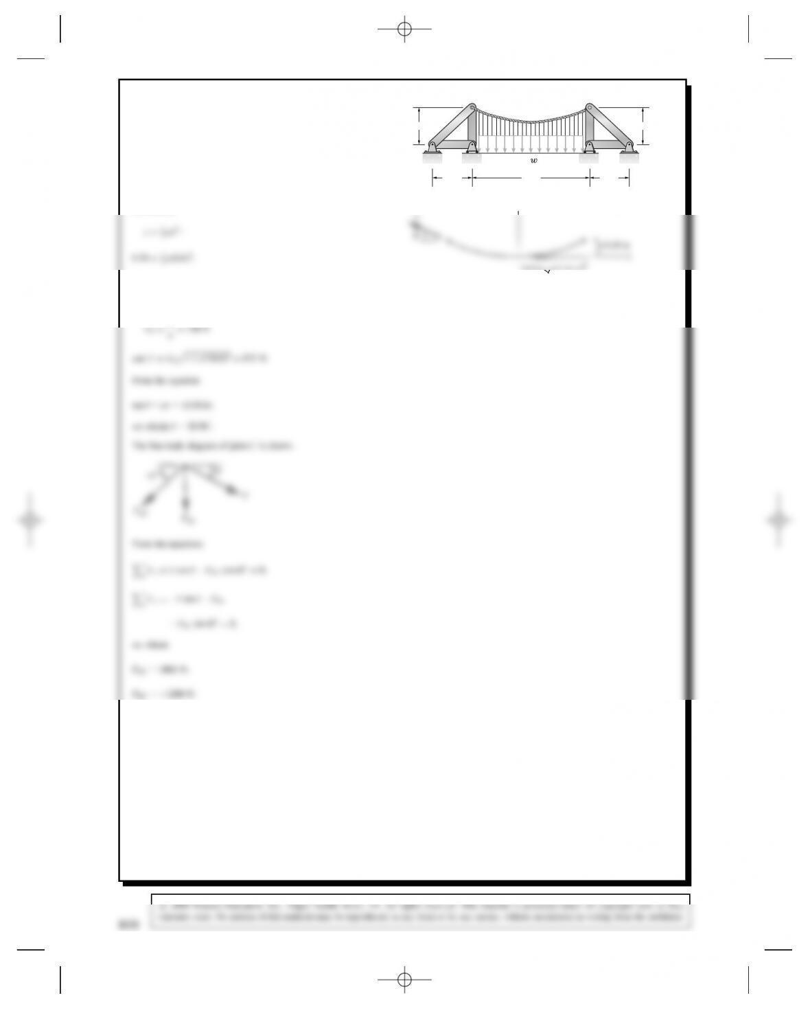
Problem 10.54 The cable supports a uniformly
distributed load wD750 N/m. The lowest point of the
cable is 0.18 m below the attachment points Cand D.
Determine the axial loads in the truss members AC
and BC.
C
0.4 m1.2 m
0.4 m
0.4 m
AB
D
EF
0.4 m
Solution:
From this equation we obtain aD1m
1.
Therefore
T0Dw
aD750 N
and TDT01Ca2⊲0.6⊳2D875 N.
From the equation
tan Dax D⊲1⊳⊲0.6⊳,
we obtain D30.96°.
The free-body diagram of joint Cis shown.
45°
θ
T
PBC
PAC
From the equations
FxDTcos PAC cos 45°D0,
FyDTsin PBC
PAC sin 45°D0,
we obtain
PAC D1061 N,
PBC D1200 N.
T
y
0.6 m
828
c
2008 Pearson Education, Inc., Upper Saddle River, NJ. All rights reserved. This material is protected under all copyright laws as they
currently exist. No portion of this material may be reproduced, in any form or by any means, without permission in writing from the publisher.