ͳͲǦͳͷȂ
E
L GEARS APPLICATION: Conveyor with moderate shock driven by a gasoline engine
Problem 10-15 Neither gear straddle mounted
Factors in Design Analysis:
Input Power: P = 3.5 hp Load distribution factor, K
m:
From Figure 10-14 and Equation 10-16
Input Speed: n
P
=1250rpm Both gears straddle mounted: 1.002
Diametral Pitch: P
d
= 10 One gear straddle mounted: 1.102
e
r of Pinion Teeth: N
P
=25 Neither gear straddle mounted: 1.252
e
d Output Speed: n
G
= 625 rpm Enter K
m
= 1.252 Neither gear straddle mounted
m
ber of gear teeth: 50.0 Overload Factor: K
o
= 2.00 Table 9-1
N
o. of Gear Teeth: N
G
= 50 Figure 10-13-Pinion Size Factor: K
s
= 0.508 0.508 Use 0.50 if P
d
> 15
C
a
l Output Speed: n
G
= 625.0 rpm Fig. 10-18-Gear Size Factor: C
s
= 0.525 0.50 0.525 0.83
D
iameter – Pinion: D
P
=2.500 in Service Factor: SF = 1.00 Use 1.00 if no unusual conditions
h
c
one angle – Gear: * = 63.43 degrees Pinion – Number of load cycles: N
P
= 1.13E+09 Input value from pertinent
t
er cone distance: A
o
= 2.795 in Gear – Number of load cycles: N
G
= 5.63E+08
F
P
itch Line Speed: v
t
= 818 ft/min Stress cycle factor-Bending Figure 10-16 <10
3
Cyc. >10
3
but<3x10
6
>3x10
6
cyc.
d
: stress analysis: W
t
= 141 lb Enter Stress cycle factor–Bending, K
L =
0.936 2.700 0.513 0.936
r
e
4
4
One possible material specification:
o
n Shaft – Torque: T
P
= 176.4 lb-in Pinion: HB 309 required: SAE 4140 OQT 1100; HB = 311
n radius of pinion: r
m
= 1.093 in Gear: HB 293 required: SAE 4140 OQT 1100; HB = 311
r
: Pressure angle:
I
= 20 degrees
–Tangential load: W
tP
= 161 lb [Eq. 10-10]
n
o
rque for shaft and bearing load analysis:
n
itial Input Data:
number of cycles.
ͳͲǦͳȂ
E
L GEARS APPLICATION: Heavy-duty conveyor with moderate shock driven by a gasoline engine
Problem 10-16 Both gears straddle mounted
Factors in Design Analysis:
Input Power: P = 5 hp Load distribution factor, K
m:
From Figure 10-14 and Equation 10-16
Input Speed: n
P
=850rpm Both gears straddle mounted: 1.005
Diametral Pitch: P
d
= 8One gear straddle mounted: 1.105
e
D
ne angle – Pinion: J = 19.44 degrees Enter: Design Life: 15000 hours See Table 9-12
one angle – Gear: * = 70.56 degrees Pinion – Number of load cycles: N
P
= 7.7E+08 Input value from pertinent
t
er cone distance: A
o
= 3.380 in Gear – Number of load cycles: N
G
= 2.7E+08
F
P
itch Line Speed: v
t
= 501 ft/min Stress cycle factor-Bending Figure 10-16 <10
3
Cyc. >10
3
but<3x10
6
>3x10
6
cyc.
G
eometry Factor: I = 0.078 Fig. 10-19 Specify materials, alloy and heat treatment, for most severe requirement.
One possible material specification:
o
n Shaft – Torque: T
P
= 370.59 lb-in Pinion: HB 330 required: SAE 1340 OQT 1100; HB = 331
n
radius of pinion: r
m
= 0.938 in Gear: HB 330 required: SAE 1340 OQT 1100; HB = 331
r
: Pressure angle:
I
= 20 degrees
o
rque for shaft and bearing load analysis:
n
itial Input Data:
number of cycles.
ͳͲǦͳȂ
E
L GEARS APPLICATION: Reciprocating saw driven by an electric motor
Problem 10-17 Both gears straddle mounted
Factors in Design Analysis:
Input Power: P = 0.75 hp Load distribution factor, K
m:
From Figure 10-14 and Equation 10-16
Input Speed: n
P
= 1800 rpm Both gears straddle mounted: 1.001
Diametral Pitch: P
d
= 20 One gear straddle mounted: 1.101
e
a
D
ne angle – Pinion: J = 14.83 degrees Enter: Design Life: 15000 hours See Table 9-12
c
one angle – Gear: * = 75.17 degrees Pinion – Number of load cycles: N
P
= 1.6E+09 Input value from pertinent
t
er cone distance: A
o
= 1.759 in Gear – Number of load cycles: N
G
= 4.3E+08
F
P
itch Line Speed: v
t
= 424 ft/min Stress cycle factor-Bending Figure 10-16 <10
3
Cyc. >10
3
but<3x10
6
>3x10
6
cyc.
t
r
G
eometry Factor: I = 0.086 Fig. 10-19 Specify materials, alloy and heat treatment, for most severe requirement.
One possible material specification:
o
n Shaft – Torque: T
P
= 26.25 lb-in Pinion: HB 280 required: SAE 1340 OQT 1200; HB = 293
n
radius of pinion: r
m
= 0.386 in Gear: HB 280 required: SAE 1340 OQT 1200; HB = 293
r
: Pressure angle:
I
= 20 degrees
o
rque for shaft and bearing load analysis:
n
itial Input Data:
number of cycles.
WORMGEARING
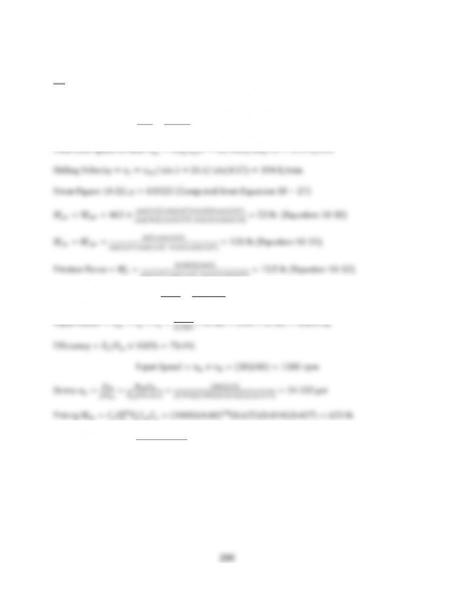
ͳͺǤ ȏͺǦͷʹ
Ȑܶ
ൌ ͻʹͶ ή ǡ ݊ீൌ ͵Ͳ
ǣܹ
௧ீ ൌܹ
௫௪ ൌ்
ಸȀଶ ൌଽଶସή
ଶǤ ൌ Ͷʹ
௦ሺସǤହሻ௦ሺଵସǤହሻିǤଷଶଷ ௦ሺସǤହሻൌ ͳͷǤͷȋͳͲǦ͵ʹȌ
ൌ ܲൌ௩ೞௐ
ଷଷ ൌሺଷଽସሻሺଵହǤହሻ
ଷଷ ൌ ͲǤͳͺͷ
ಸ
ܹ
௧ோ ܹ
௧ீȂ
࣌ࡳൌ ܘܛܑ െ ܛܔܑܐܜܔܡܐܑܐ܍ܚܜܐ܉ܖ࢙ࢇ࢚ ൌ ܘܛܑܗܚܘܐܗܛܘܐܗܚ܊ܚܗܖܢ܍
ȋͳͲǦͳͺǤȌ
Spreadsheet solution to Problem 10-18. Small differences from the solution on the preceding
page are due to rounding differences and reading of data from graphs, rather than calculations.
W
ormgearing – Design Problem: 10-18
Pitch line speed – Gear: 31.42 ft/min
Sliding velocity v
s
= 394 ft/min
Desired output torque: T
o
= 924 lb-in Coefficient of friction: 0.032 If v
s
> 10 ft/min
Output speed: n
G
=30rpm Forces: (lb) Gear Worm
Velocity Ratio: VR = 40 Tangential: 462 53
Radial: 120 120
Diametral pitch: P
d
=10 Axial: 53 462
No. of worm threads: N
W
= 1Friction force, W
f
= 15.6 lb
Required No. of gear teeth: N
G
= 40 Power:
Specify No. of gear teeth: N
G
=40 Power output from gear: 0.440 hp
Normal pressure angle:
I
n
= 14.5 degrees Power loss – friction: 0.186 hp
Additional Computed Results:
Input Data:
Design Decisions:
298
x WormgearingͺͳͲǡ
ǡ
Ǥ
x ǡ
Ǥ
299
ͳͲǦͳͻͳͲǦʹͲȂ
a
ring – Design Problem: 10-19a and 20a
v
e procedure] Pitch line speed – Gear: 39.27 ft/min
Sliding velocity v
s
= 473 ft/min
T
rial output torque: T
o
= 202 lb–in Coefficient of friction: 0.030 If v
s
> 10 ft/min – Eq. 10-27
Output speed: n
G
=90rpm Forces: (lb) Gear Worm
Velocity Ratio: VR = 20 Tangential: 242 28
Diametral pitch: P
d
=12 Axial: 28 242
of worm threads: N
W
= 1Friction force, W
f
= 7.5 lb
No. of gear teeth: N
G
= 20 Power:
No. of gear teeth: N
G
=20 Power output from gear: 0.289 hp
a
l pressure angle:
I
n
= 14.5 degrees Power loss – friction: 0.107 hp
Power input: 0.396 hp
c
tual input speed: n
W
= 1800 rpm Efficiency: 72.9 %
C
0.875
/D
W
= 1.29 LOW Dynamic factor: K
v
= 0.968
r
worm diameter Should be >1.6 and <3.0 Bending stress on gear: 19190 psi– Using specified gear face widt
h
c
ular pitch of gear: p
G
= 0.262 in Allowable stresses-Bronze: Manganese = 17000 psi; Phosphor = 24000 psi
x
ial pitch of worm: p
xW
= 0.262 in
L
ead of the worm: L = 0.262 in Type of bronze:/D
G
—>
>2.5 in <2.5 in >8 in <8 in >25 in <25 i
n
a
c
d
gear face width: F
e
=0.500 in Enter: C
v
= 0.392
Design decision Rated tangential load: W
tR
= 242 lb Eq. 10–42
Must be > W
t
= 242 lb
Adjusted output torque until limits reached on either bending or surface dura
b
Surface Durability: [Hardened steel worm; bronze gear]
Additional Computed Results:
Input Data:
t
ed Results and Additional Inputs:
Normal pressure angle,
I
n
ͳͲǦͳͻͳͲǦʹͲȂ
a
ring – Design Problem: 10-19b and 20b
Pitch line speed – Gear: 78.54 ft/min
Sliding velocity v
s
= 478 ft/min
e
sired output torque: T
o
= 484 lb-in Coefficient of friction: 0.030 If v
s
> 10 ft/min
Output speed: n
G
=90rpm Forces: (lb) Gear Worm
Velocity Ratio: VR = 20 Tangential: 290 58
Diametral pitch: P
d
=12 Axial: 58 290
N
o. of worm threads: N
W
= 2Friction force, W
f
= 9.1 lb
e
d No. of gear teeth: N
G
= 40 Power:
i
fy No. of gear teeth: N
G
=40 Power output from gear: 0.691 hp
r
mal pressure angle:
I
n
= 14.5 degrees Power loss – friction: 0.131 hp
Power input: 0.822 hp
u
Additional Computed Results:
Input Data:
p
uted Results and Additional Inputs:
ͳͲǦͳͻͳͲǦʹͲȂ
a
ring – Design Problem: 10-19c and 20c
Pitch line speed – Gear: 157.08 ft/min
Sliding velocity v
s
= 497 ft/min
e
sired output torque: T
o
= 878 lb-in Coefficient of friction: 0.029 If v
s
> 10 ft/min
N
e
d No. of gear teeth: N
G
= 80 Power:
i
fy No. of gear teeth: N
G
=80 Power output from gear: 1.254 hp
r
mal pressure angle:
I
n
= 14.5 degrees Power loss – friction: 0.127 hp
Power input: 1.381 hp
Actual input speed: n
W
= 1800 rpm Efficiency: 90.8 %
e
cify worm diameter: D
W
= 1.000 in Enter: Lewis form factor: y = 0.100 —-—-> 0.100 0.125 0.150 0.17
5
u
al center distance: C = 3.833 in Normal circular pitch: 0.248 in
C
0.875
/D
W
= 3.24 HIGH Dynamic factor: K
v
= 0.884
e
r worm diameter Should be >1.6 and <3.0 Bending stress on gear: 23987 psi [Using effective gear face widt
h
C
ircular pitch of gear: p
G
= 0.262 in Allowable stresses-Bronze: Manganese = 17000 psi; Phosphor = 24000 psi
Axial pitch of worm: p
xW
= 0.262 in
Lead of the worm: L = 1.047 in Type of bronze:/D
G
—>
>2.5 in <2.5 in >8 in <8 in >25 in <25 i
n
Surface Durability: [Hardened steel worm; bronze gear]
Additional Computed Results:
Input Data:
p
uted Results and Additional Inputs:
Normal pressure angle,
I
n
SUMMARYOFRESULTSOFTHETHREEPARTSOFPROBLEMS19AND20:
Problems 10-19 and 10-20 COMPARISON OF THREE PROPOSED DESIGNS
Summary See details on the preceding three spreadsheets
Given data:
Diametral pitch, Pd = 12
Velocity ratio, VR = 20
Output power (hp), Po = 0.289 0.691 1.254
Gear bending stress (psi) 19190 23963 23987
Limits in
Bold
Allowable bending stress (psi) 24000 24000 24000
Rated load for surface durability
Limits in
Worm diameter is too small for Design C. See Equations 10-52 and 10-53
Design A is limited by surface durability
Designs B and C are limited by bending stress in gear teeth.
As number of threads in worm increases:
Lead angle increases
ͳͲǦͳͻͳͲǦʹͲȂǡDWαͲǤͲͲǤ
o
rmgearing – Design Problem: 10-19a and 20a
[
Iterative procedure] Pitch line speed – Gear: 39.27 ft/min
Sliding velocity vs = 332 ft/min
Trial output torque: To = 202 lb-in Coefficient of friction: 0.035 If vs> 10 ft/min – Eq. 10-27
Output speed: nG =90rpm Forces: (lb) Gear Worm
Velocity Ratio: VR = 20 Tangential: 242 38
C0.875 /DW = 1.66 OK Dynamic factor: Kv = 0.968
Should be >1.6 and <3.0 Bendi n g stress o n gear: 19259 p si – Using specified gear face widt
h
Circular pitch of gear: pG = 0.262 in Allowable stresses-Bronze: Manganese = 17000 psi; Phosphor = 24000 psi
Axial pitch of worm: pxW = 0.262 in
Lead of the worm: L = 0.262 in Type of bronze:/DG —->
>2.5 in <2.5 in >8 in <8 in >25 in <25 in
Design decision Rated tangential load: W tR = 242 lb Eq. 10-42
Must be > W t = 242 lb
Adjusted output torque until limits reached on either bending or surface dura
b
Using chilled phosphur bronze, surface durability controls this design.
Surface Durability: [Hardened steel worm; bronze gear]
Modified-changed Dw
Additional Computed Results:
Input Data:
304
Spreadsheet solution to Problem 10-21.
a
ring – Design Problem: 10-21
Pitch line speed – Gear: 62.83 ft/min
Sliding velocity v
s
= 184 ft/min
e
sired output torque: T
o
= 984 lb-in Coefficient of friction: 0.045 If v
s
> 10 ft/min
Output speed: n
G
=80rpm Forces: (lb) Gear Worm
Velocity Ratio: VR = 7.5 Tangential: 656 276
Diametral pitch: P
d
=5 Axial: 276 656
N
o. of worm threads: N
W
= 2Friction force, W
f
= 35.0 lb
e
d No. of gear teeth: N
G
= 15 Power:
i
fy No. of gear teeth: N
G
=15 Power output from gear: 1.250 hp
r
mal pressure angle:
I
n
= 25 degrees Power loss – friction: 0.195 hp
Power input: 1.445 hp
Actual input speed: n
W
= 600 rpm Efficiency: 86.5 %
Additional Computed Results:
One possible solution
Input Data:
p
uted Results and Additional Inputs:
Normal pressure
305
Spreadsheet solution to Problem 10-22.
a
ring – Design Problem: 10-22
Pitch line speed – Gear: 235.62 ft/min
Diametral pitch: P
d
=12 Axial: 76 70
N
o. of worm threads: N
W
= 6Friction force, W
f
= 4.0 lb
e
d No. of gear teeth: N
G
= 18 Power:
i
fy No. of gear teeth: N
G
=18 Power output from gear: 0.500 hp
r
mal pressure angle:
I
n
= 25 degrees Power loss – friction: 0.040 hp
Power input: 0.540 hp
Actual input speed: n
W
= 1800 rpm Efficiency: 92.6 %
A
ctual velocity ratio: VR = 3 14.5 20
c
Stresses:
Additional Computed Results:
p
uted Results and Additional Inputs:
Normal pressure
306
Spreadsheet solution to Problem 10-23.
gearing – Design Problem: 10-23
Pitch line speed – Gear: 117.81 ft/min
Sliding velocity vs = 1067 ft/min
uired No. of gear teeth: NG = 80 Power:
ecify No. of gear teeth: NG =80 Power output from gear: 3.000 hp
N
ormal pressure angle:
I
n = 14.5 degrees Power loss – friction: 0.570 hp
Power input: 3.570 hp
Actual input speed: nW = 1800 rpm Efficiency: 84.0 %
Actual velocity ratio: VR = 40 14.5 20 25
Gear pitch diameter: DG = 10 in Bending Stress on Gear:
S
pecify worm diameter: DW = 2.25 in Enter: Lewis form factor: y = 0.100 ——–> 0.100 0.125 0.150
A
ctual center distance: C = 6.125 in Normal circular pitch: 0.390 in
C0.875 /DW = 2.17 OK Dynamic factor: Kv = 0.911
Should be >1.6 and <3.0 Bending stress on gear: 21689 psi [Using effective gear fac
e
Circular pitch of gear: pG = 0.393 in Allowable stresses-Bronze: Manganese = 17000 psi; Phosphor = 240
0
Axial pitch of worm: pxW = 0.393 in
Lead of the worm: L = 0.785 in Type of bronze:/D G —>
>2.5 in <2.5 in >8 in <8 in >25 in
Rated tangential load: W tR = 990 lb
Must be > W t = 840 lb
NOTE: For the Ratio correction factor, if #NUM! appears, the argument
equation for Cm is negative resulting in an invalid result.
Surface Durability: [Hardened steel worm; bronze gear]
Stresses:
Additional Computed Results:
Input Data:
mputed Results and Additional Inputs:
Lewis form facto
r
Normal pressure an
g
Spreadsheet solution to Problem 10-24A.
ǡDWαʹǤͲͲǡǡ
ǡDWαͳǤͷǤǤ
gearing – Design Problem: 10-24A
Pitch line speed – Gear: 26.18 ft/min
Sliding velocity v
s
= 315 ft/min
Desired output torque: T
o
= 1200 lb-in Coefficient of friction: 0.036 If v
s
> 10 ft/min
Normal pressure angle:
I
n
= 14.5 degrees Power loss – friction: 0.171 hp
Power input: 0.552 hp
Actual input speed: n
W
= 600 rpm Efficiency: 69.1 %
Actual velocity ratio: VR = 30 14.5 20 25
Stresses:
Additional Computed Results:
Input Data:
o
mputed Results and Additional Inputs:
Normal pressure an
g
Spreadsheet solution to Problem 10-24A – Modified: DWαͳǤͷǤ
ͳͲǦʹͶǤ
gearing – Design Problem: 10-24A – Revised
Pitch line speed – Gear: 26.18 ft/min
q
uired No. of gear teeth: N
G
= 30 Power:
p
ecify No. of gear teeth: N
G
=30 Power output from gear: 0.381 hp
Normal pressure angle:
I
n
= 14.5 degrees Power loss – friction: 0.159 hp
Power input: 0.540 hp
Actual input speed: n
W
= 600 rpm Efficiency: 70.6 %
W
Larger worm diameter
Additional Computed Results:
o
mputed Results and Additional Inputs:
Normal pressure an
g
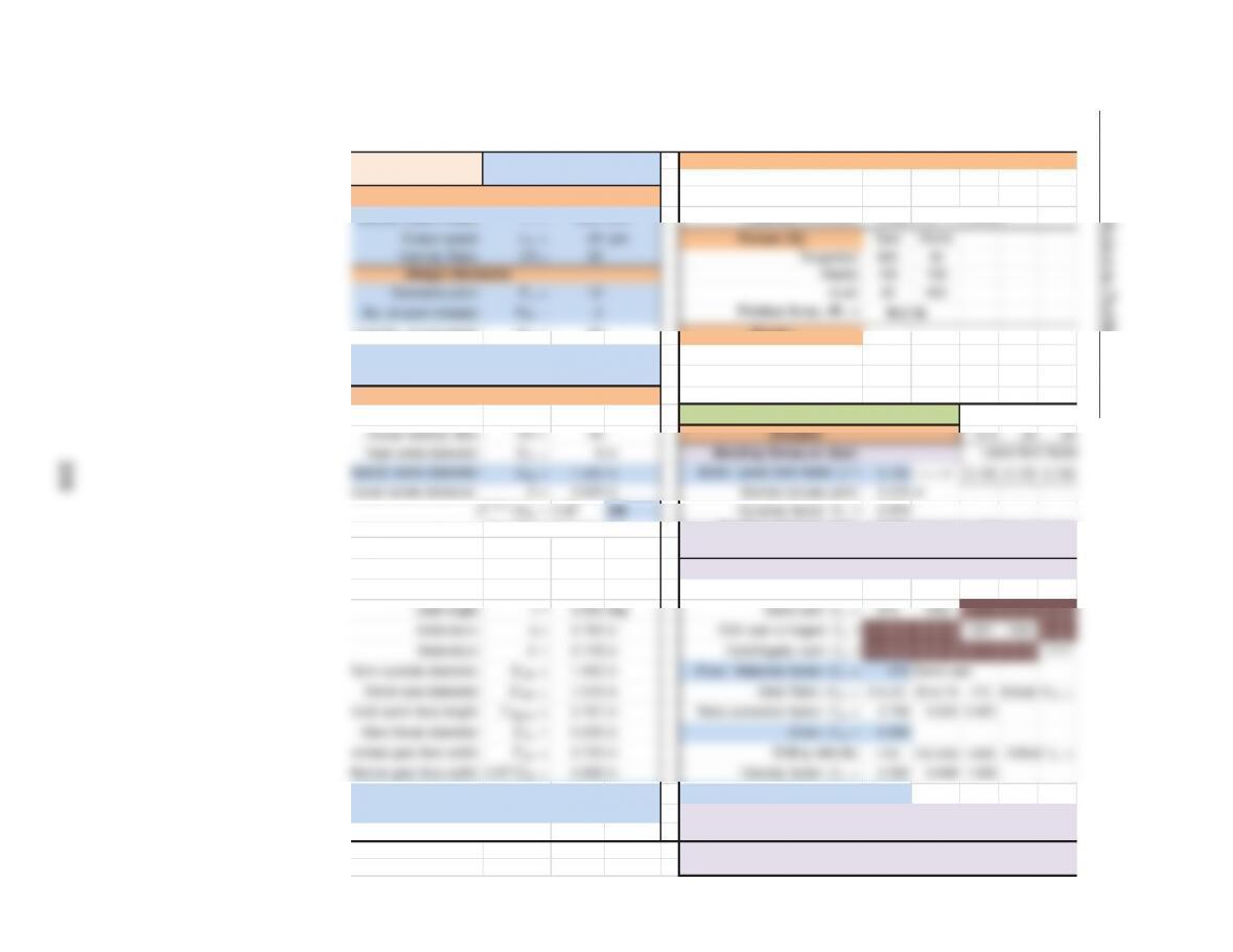
Spreadsheet solution to Problem 10-24B.
gearing – Design Problem: 10-24B
Pitch line speed – Gear: 31.42 ft/min
Sliding velocity v
s
= 199 ft/min
Desired output torque: T
o
= 1200 lb-in Coefficient of friction: 0.043 If v
s
> 10 ft/min
uired No. of gear teeth: N
G
= 60 Power:
ecify No. of gear teeth: N
G
=60 Power output from gear: 0.381 hp
N
ormal pressure angle:
I
n
= 14.5 degrees Power loss – friction: 0.110 hp
Power input: 0.491 hp
Actual input speed: n
W
= 600 rpm Efficiency: 77.6 %
Input Data:
mputed Results and Additional Inputs:
Normal pressure an
g
Additional Computed Results:
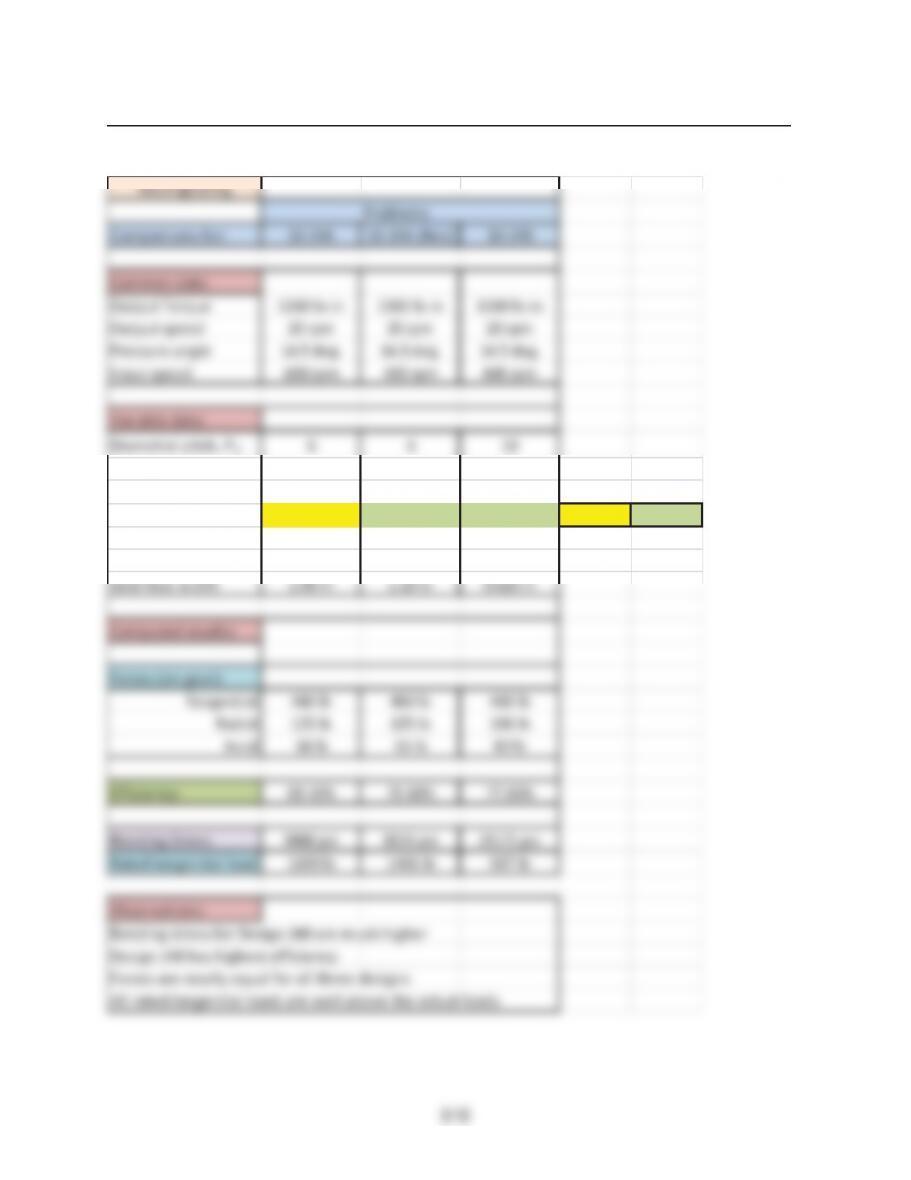
COMPARISONOFTHERESULTSFORPROBLEMS10Ǧ24A,10Ǧ24A(REV.),AND10Ǧ24B
Wormgearing
Problems
Comparisonsfor:10Ͳ24A 10Ͳ24A(Rev) 10Ͳ24B
Commondata:
OutputTorque 1200lbͲin 1200lbͲin 1200lbͲin
Outputspeed 20rpm 20rpm 20rpm
Pressureangle 14.5deg. 14.5deg. 14.5deg.
Inputspeed 600rpm 600rpm 600rpm
Variabledata:
Diametralpitch,P
d
6610
No.ofwormthreads 1 1 2
No.ofgearteeth303060
Wormdiameter 2.00in 1.75in 1.25in Toolarge OK
Geardiameter 5.00in 5.00in 6.00in
Centerdistance 3.5in 3.375in 3.625in