275
CHAPTER 10
HELICAL GEARS, BEVEL GEARS
AND WORMGEARING
ͳǤ ǣܲௗൌͺǢ߶௧ൌͳͶଵ
ଶιǢܰீൌͶͷǢܨൌʹǤͲͲǢ߰ൌ͵Ͳι
Ȍ ܲൌͷǤͲǢ݊ீൌͳʹͷͲǢൌܶൌଷሺହǤሻ
ଵଶହ ൌʹͷʹή
Ȍ ܰൌͳͷǢǢܭൌͳǤͷͲ
ݏ௧ ൌܹ௧ܲௗ
ܨܬൈܭܭ௦ܭܭܭ௩Ǣܭ௦ൌܭൌͳǤͲ
ܬαͲǤ͵ͺͳͲǦͷȋȌͷǦǤKǦαͲǤͻ
276
ݏ௧ ൌሺͺͻǤሻሺͺሻ
ሺʹǤͲͲሻሺͲǤ͵ͻሻሺͳǤͷͲሻሺͳǤͲሻሺͳǤʹ͵ሻሺͳǤͲሻሺͳǤͷͷሻൌʹͺ
ݏൌܥඨܹ௧ܭܭ௦ܭܭ௩
ܨܦܫൌͳͻͲඨሺͺͻǤሻሺͳǤͷͲሻሺͳǤͲሻሺͳǤʹ͵ሻሺͳǤͷͷሻ
ሺʹǤͲͲሻሺͳǤͺͷሻሺͲǤʹͲሻ
ݏൌ͵ʹʹͺǣሾܫͳͲെͳǤሿ
Ȍ pecifycastironbecauseoflowstresses
ʹǤ ǣܲൌʹǤͷͲǢܰൌͳǢܰீൌͶͺǢܲௗൌͳʹǢ߶ൌʹͲιǢ߰ൌͶͷι
ܨൌͳǤͷͲǢൌܶൌଷሺଶǤହሻ
ଵହ ൌͻͲǤͲή
݊
ൌͳͷͲ
Ȍ ܭൌͳǤʹͷሺܮ݄݅݃ݐݏ݄ܿ݇ሻǢܭ௦ൌܭൌͳǤͲͲǢܬ؆ͲǤ͵Ͳ
277
͵Ǥ ǣܲൌͳͷǢܰൌͳʹǢܰீൌ͵ǢܲௗൌǢ߶௧ൌͳͶଵ
ଶιǢ߰ൌͶͷιǢܨൌͳǤͲͲ
Ȍ ܹ௧ൌ்
ಸȀଶൌସଷ
ǤȀଶൌͳͶ͵
ܹ௫ൌܹ௧ݐܽ݊߰ൌͳͶ͵݈ܾൈݐܽ݊ͶͷιൌͳͶ͵݈ܾ
Ȍ ݒ௧ൌߨܦீ݊ீȀͳʹൌߨሺǤͲͲሻሺʹʹͲͲሻȀͳʹൌ͵ͶͷȀ
ܣ௩ൌͻǢܭ௩ൌͳǤͶͶǢܬൌͲǤ͵Ͳሺܧݏݐ݅݉ܽݐ݁݀ሻǡܫൌͲǤͳͻͲሺሻ
278
Ȍ Specify:DuctileironASTMA53660Ǧ40Ǧ18;࢙ࢇ࢚ ൌܘܛܑǡ࢙ࢇࢉ ൌૠૠܘܛܑ
ͶǤ ǣܲൌͲǤͷͲǢ݊ൌ͵ͶͷͲǢܲௗ ൌʹͶǢ߶ൌͳͶଵ
ଶι
߰ൌͶͷιǢܰீൌʹǢܰൌͳǢܨൌͲǤʹͷǢെെܭൌͳǤͷͲ
ͺǦͶͶǢܲௗൌͳǤͻǢܦீൌͶǤʹͶ͵Ǣܦൌே
ൌଵ
ଵǤଽൌͲǤͻͶ͵
ܶൌ
ଷሺሻ
ಸൌଷሺǤହሻ
ଷସହ ൌͻǤͳ͵ή
Ȍ ܹ௧ൌ்
ಸȀଶൌଽǤଵଷ
ସǤଶସଷȀଶൌͶǤ͵Ͳ
Ȍ ݒ௧ൌߨܦீ݊ீȀͳʹൌߨሺͶǤʹͶ͵ሻሺ͵ͶͷͲሻȀͳʹൌ͵ͺ͵ʹȀ
279
SPREADSHEETSFORSOLUTIONSTOCHAPTER10PROBLEMS:
ǡǡǤ
ͳͲǤ
ǤǤǤ
x ͷͳͳǤ
280
ͷǤ
Ǥ
O
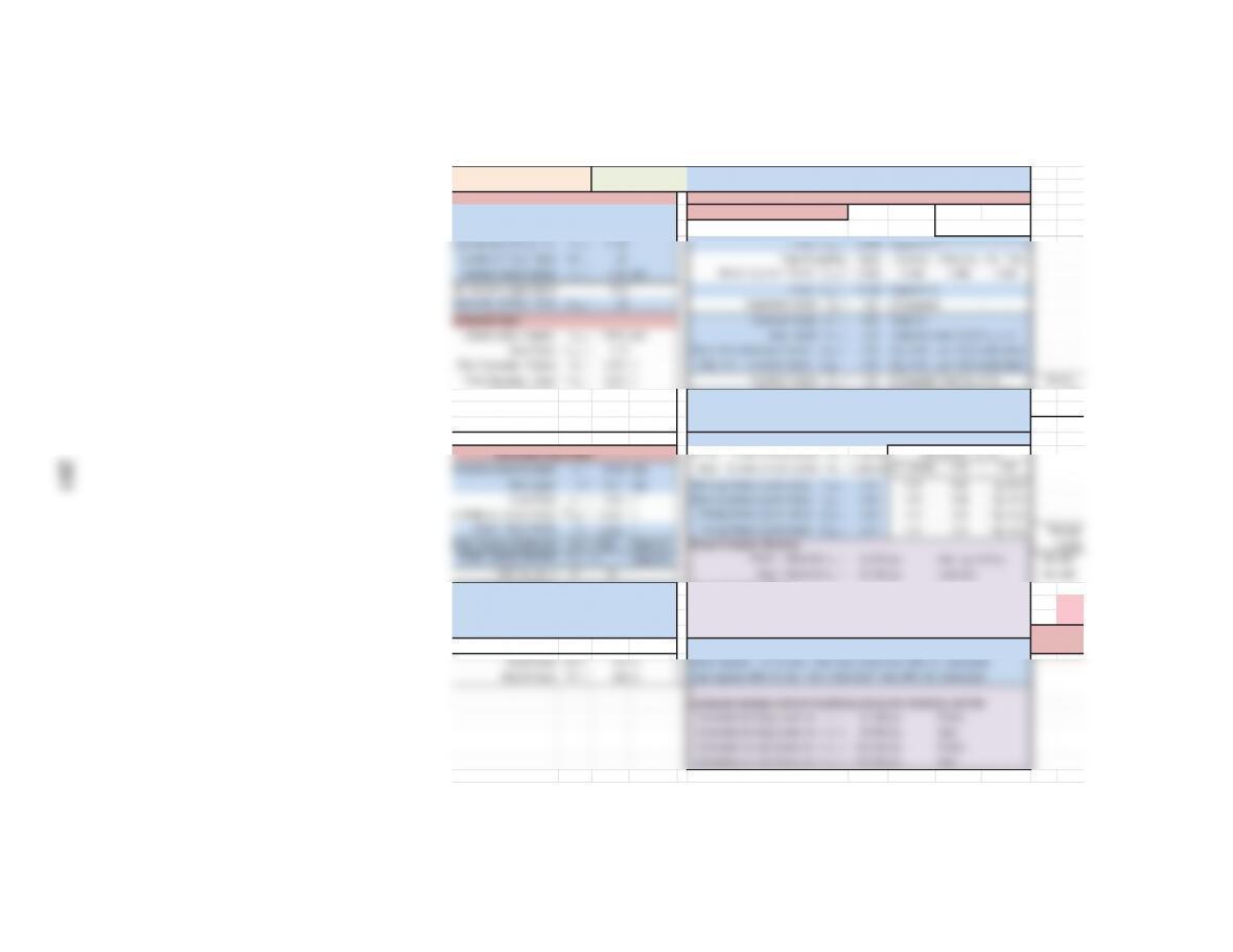
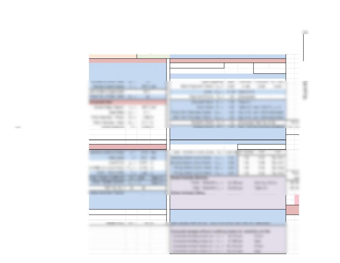
F HELICAL GEARS-U.S. APPLICATION: Milling machine driven by an electric motor
Example Problem 10-3
n
itial Input Data: Factors in Design Analysis:
Input Power: P = 65 hp Alignment Factor,K
m
=1.0+C
pf
+C
ma
If F<1.0 If F>1.0 F/D
P
= 1.09
Input Speed: n
P
= 3450 rpm Pinion Proportion Factor, C
pf
= 0.084 0.099 [0.50 < F/D
P
< 2.00]
ve
rse Diametral Pitch, P
d
:P
d
= 11.59 Enter: C
pf
=0.099Figure 9-12
Number of Pinion Teeth: N
P
=24 Type of gearing: Open Commer. Precision Ex. Prec.
Desired Output Speed: n
G
= 1100 rpm Mesh Alignment Factor,C
ma
= 0.284 0.162 0.096 0.061
u
ted number of gear teeth: 75.3 Enter: C
ma
=0.162Figure 9-13
C
hosen No. of Gear Teeth: N
G
= 75 Alignment Factor: K
m
= 1.26 [Computed]
C
omputed data: Overload Factor: K
o
=1.50Table 9-1
Actual Output Speed: n
G
= 1104.0 rpm Size Factor: K
s
=1.00Table 9-2: Use 1.00 if P
d
>= 5
Gear Ratio: m
G
= 3.13 Pinion Rim Thickness Factor: K
BP
=1.00Fig. 9-14: Use 1.00 if solid blank
Pitch Diameter – Pinion: D
P
=2.071 in Gear Rim Thickness Factor: K
BG
= 1.00 Fig. 9-14: Use 1.00 if solid blank
Pitch Diameter – Gear: D
G
= 6.471 in Dynamic Factor: K
v
= 1.35 [Computed: See Fig. 9-16]
Center Distance: C = 4.271 in Service Factor: SF = 1.00 Use 1.00 if no unusual conditions B = 0.630
3
Pitch Line Speed: v
t
= 1870 ft/min C = 70.71
Transmitted Load: W
t
= 1147 lb Reliability Factor: K
R
= 1.25 Table 9-11: Use 1.00 for R = .99
Enter: Design Life: 10000 hours See Table 9-7
e
nding Geometry Factors: Stress Analysis: Pitting
Pinion: J
P
= 0.480
Fig 10-5,6,7
Pinion: Required s
ac
= 180,257 psi See Fig. 9-19 or HB 469
Gear: J
G
= 0.526
Fig 10-5,6,7
Gear: Required s
ac
= 176,295 psi Table 9-9 HB 457
:
Pitting Geometry Factor: I = 0.202
Tab. 10-1,2
Specify materials, alloy and heat treatment, for most severe requirement. Red: HB >
4
REF: m
G
= 3.13 One possible material specification: Steel pinion and gear: Carburized, Grade 1 for through
h
Axial Force: W
x
= 307 lb Pinion requires HRC 58 min.: SAE 4320 SOQT 450; HRC 59; Carburized
Radial Force: W
r
= 432 lb Gear requires HRC 58 min.: SAE 4320 SOQT 450; HRC 59; Carburized
Computed stresses without modifying factors for reliability and life:
Computed bending stress no. = s
t
= 31,449 psi Pinion
Computed bending stress no. = s
t
= 28,699 psi Gear
Computed contact stress no. = s
c
= 128,343 psi Pinion
Computed contact stress no. = s
c
= 128,343 psi Gear
For K
v
:
282
ͳͲǦͷȂǤ
Problem 10-5
In
itial Input Data: Factors in Design Analysis:
Input Power: P = 5 hp Alignment Factor,K
m
=1.0+C
pf
+C
ma
If F<1.0 If F>1.0 F/D
P
= 1.20
Input Speed: n
P
= 1200 rpm Pinion Proportion Factor, C
pf
= 0.095 0.098 [0.50 < F/D
P
< 2.00]
v
erse Diametral Pitch, P
d
:P
d
= 18 Enter: C
pf
= 0.098 Figure 9-12
Center Distance: C = 2.056 in Service Factor: SF = 1.00 Use 1.00 if no unusual conditions B = 0.
8
Pitch Line Speed: v
t
= 314 ft/min C = 59
Transmitted Load: W
t
= 525 lb Reliability Factor: K
R
= 1.00 Table 9-11: Use 1.00 for R = .99
Enter: Design Life: 15000 hours See Table 9-12
Secondary Input Data: Pinion – Number of load cycles: N
P
= 1.1E+09 Guidelines: Y
N
, Z
N
T
ransverse pressure angle:
I
t
= 20.00 deg Gear – Number of load cycles: N
G
= 3.5E+08 10
7
cycles >10
7
<10
7
Helix angle: \=25.0 deg Bending Stress Cycle Factor: Y
NP
= 0.94 1.00 0.94 Fig. 9-21
Axial Pitch: p
x
= 0.374 in Bending Stress Cycle Factor: Y
NG
= 0.96 1.00 0.96 Fig. 9-21
c
e Width (2 x Axial Pitch): F
mi n
= 0.749 in Pitting Stress Cycle Factor: Z
NP
= 0.90 1.00 0.90 Fig. 9-22
Enter: Face Width: F = 1.200 in Pitting Stress Cycle Factor: Z
NG
= 0.92 1.00 0.92 Fig. 9-22
Enter: Elastic Coefficient: Cp =2300 Table 9-7 Stress Analysis: Bending
Enter: Quality Number: A
v
= 11 Table 9-5 Pinion: Required s
at
= 42,786 psi See Fig. 9-18 or HB 38
8
Pinion: J
P
=0.453
Fig 10-5,6,7
Pinion: Required s
ac
= 179,572 psi See Fig. 9-19 or HB 46
7
Gear: J
G
= 0.486
Fig 10-5,6,7
Gear: Required s
ac
= 175,668 psi Table 9-9 HB 45
5
r
:Pitting Geometry Factor: I = 0.205
Tab. 10-1,2
Specify materials, alloy and heat treatment, for most severe requirement. Red: HB
REF: m
G
= 3.11 One possible material specification: Steel pinion and gear: Carburized, Grade 1 for throu
g
Axial Force: W
x
= 245 lb Pinion requires HRC 58 min.: SAE 4118 DOQT 300; HRC 62; Carburized
Gr
a
Thro
u
ͳͲǦȂ
F
HELICAL GEARS-U.S. APPLICATION: Milling machine driven by an electric motor
Problem 10-6
t
ial Input Data: Factors in Design Analysis:
Input Power: P = 20 hp Alignment Factor,Km=1.0+Cpf +Cma If F<1.0 If F>1.0 F/DP = 1.04
Input Speed: nP = 550 rpm Pinion Proportion Factor, Cpf = 0.079 0.098 [0.50 < F/DP< 2.00]
s
e Diametral Pitch, Pd:Pd = 10 Enter: C pf =0.098Figure 9-12
N
umber of Pinion Teeth: NP =24 Type of gearing: Open Commer. Precision Ex. Prec.
Desired Output Speed: nG = 185 rpm Mesh Alignment Factor,Cma = 0.288 0.166 0.099 0.063
d number of gear teeth: 71.4 Enter: Cma =0.099Figure 9-13
o
sen No. of Gear Teeth: NG = 72 Alignment Factor: Km = 1.20 [Computed]
o
mputed data: Overload Factor: K o = 1.50 Table 9-1
Actual Output Speed: nG = 183.3 rpm Size Factor: K s = 1.00 Table 9-2: Use 1.00 if Pd>= 5
Gear Ratio: mG = 3.00 Pinion Rim Thickness Factor: KBP = 1.00 Fig. 9-14: Use 1.00 if solid blank
P
itch Diameter – Pinion: DP=2.400 in Gear Rim Thickness Factor: K BG = 1.00 Fig. 9-14: Use 1.00 if solid blank
Pitch Diameter – Gear: DG = 7.200 in Dynamic Factor: Kv = 1.16 [Computed: See Fig. 9-16]
Center Distance: C = 4.800 in Service Factor: SF = 1.00 Use 1.00 if no unusual conditions B = 0.6
3
Pitch Line Speed: vt = 346 ft/min C = 70.
7
Transmitted Load: Wt = 1910 lb Reliability Factor: K R = 1.25 Table 9-11: Use 1.00 for R = .99
Enter: Design Life: 15000 hours See Table 9-12
Secondary Input Data: Pinion – Number of load cycles: NP = 5.0E+08 Guidelines: YN, ZN
n
7
7
7
REF: NP, NG = 24 72 Gear: Required sat = 38,931 psi Table 9-9 HB 338
d
ing Geometry Factors: Stress Analysis: Pitting
Pinion: JP =0.480
Fig 10-5,6,7
Pinion: Required sac = 173,320 psi See Fig. 9-19 or HB 448
Gear: JG = 0.526
Fig 10-5,6,7
Gear: Required sac = 167,788 psi Table 9-9 HB 431
itting Geometry Factor: I = 0.220
Tab. 10-1,2
Specify materials, alloy and heat treatment, for most severe requirement. Red: HB >
For Kv:
284
ͳͲǦȂ
F
HELICAL GEARS-U.S. APPLICATION: Punch press driven by an electric motor
Problem 10-7
t
ial Input Data: Factors in Design Analysis:
Input Power: P = 50 hp Alignment Factor,Km=1.0+Cpf +Cma If F<1.0 If F>1.0 F/DP = 0.63
Input Speed: nP = 900 rpm Pinion Proportion Factor, Cpf = 0.038 0.056 [0.50 < F/DP< 2.00]
s
e Diametral Pitch, Pd:Pd = 6Enter: C pf = 0.056 Figure 9-12
N
umber of Pinion Teeth: NP =24 Type of gearing: Open Commer. Precision Ex. Prec.
Desired Output Speed: nG = 227.5 rpm Mesh Alignment Factor,Cma = 0.288 0.166 0.099 0.063
e
d number of gear teeth: 94.9 Enter: Cma = 0.166 Figure 9-13
o
sen No. of Gear Teeth: NG = 95 Alignment Factor: Km = 1.22 [Computed]
o
mputed data: Overload Factor: K o = 1.75 Table 9-1
Actual Output Speed: nG = 227.4 rpm Size Factor: K s = 1.00 Table 9-2: Use 1.00 if Pd>= 5
Gear Ratio: mG = 3.96 Pinion Rim Thickness Factor: K BP = 1.00 Fig. 9-14: Use 1.00 if solid blank
P
itch Diameter – Pinion: DP=4.000 in Gear Rim Thickness Factor: K BG = 1.00 Fig. 9–14: Use 1.00 if solid blank
Pitch Diameter – Gear: DG = 15.833 in Dynamic Factor: Kv = 1.26 [Computed: See Fig. 9-16]
Center Distance: C = 9.917 in Service Factor: SF = 1.00 Use 1.00 if no unusual conditions B = 0.6
3
Pitch Line Speed: vt = 942 ft/min C = 70.
7
Transmitted Load: Wt = 1751 lb Reliability Factor: K R = 1.25 Table 9-11: Use 1.00 for R = .99
Enter: Design Life: 15000 hours See Table 9-12
Secondary Input Data: Pinion – Number of load cycles: NP = 8.1E+08 Guidelines: YN, ZN
n
sverse pressure angle:
I
t = 20.00 deg Gear – Number of load cycles: NG = 2.0E+08 10
7
cycles >10
7
<10
7
Helix angle: \=25.0 deg Bending Stress Cycle Factor: YNP = 0.94 1.00 0.94 Fig. 9-21
Axial Pitch: px = 1.123 in Bending Stress Cycle Factor: YNG = 0.96 1.00 0.96 Fig. 9-21
Width (2 x Axial Pitch): Fmi n = 2.246 in Pitting Stress Cycle Factor: ZNP = 0.90 1.00 0.90 Fig. 9-22
Enter: Face Width: F = 2.500 in Pitting Stress Cycle Factor: Z NG = 0.93 1.00 0.93 Fig. 9-22
n
ter: Elastic Coefficient: Cp =2300 Table 9-7 Stress Analysis: Bending
Enter: Quality Number: Av = 9Table 9-5 Pinion: Required sat = 32,253 psi See Fig. 9-18 or HB 252
REF: NP, NG = 24 95 Gear: Required sat = 29,607 psi Table 9-9 HB 217
d
ing Geometry Factors: Stress Analysis: Pitting
Pinion: JP = 0.465 Fig 10–5,6,7 Pinion: Required sac = 147,637 psi See Fig. 9-19 or HB 368
Gear: JG = 0.496 Fig 10–5,6,7 Gear: Required sac = 142,875 psi Table 9-9 HB 353
P
itting Geometry Factor: I = 0.220 Tab. 10-1,2 Specify materials, alloy and heat treatment, for most severe requirement. Red: HB >
Grad
For Kv:
Throug
h
ͳͲǦͺȂ
N
OF HELICAL GEARS-U.S. APPLICATION: Small cement mixer driven by a gasoline engine
Problem 10–8
Initial Input Data: Factors in Design Analysis:
Input Power: P = 2.5 hp Alignment Factor,K
m
=1.0+C
pf
+C
ma
If F<1.0 If F>1.0 F/D
P
= 1.05
Input Speed: n
P
= 900 rpm Pinion Proportion Factor, C
pf
= 0.080 0.089 [0.50 < F/D
P
< 2.00]
s
verse Diametral Pitch, P
d
:P
d
= 12 Enter: C
pf
= 0.089 Figure 9-12
Pitch Line Speed: v
t
= 393 ft/min C = 54.
7
Transmitted Load: W
t
= 210 lb Reliability Factor: K
R
= 1.00 Table 9-11: Use 1.00 for R = .99
Enter: Design Life: 8000 hours See Table 9-12
Secondary Input Data: Pinion – Number of load cycles: N
P
= 4.3E+08 Guidelines: Y
N
, Z
N
Gear: J
G
= 0.512
Fig 10-5,6,7
Gear: Required s
ac
= 68,583 psi Table 9-9 HB 123
e
r: Pitting Geometry Factor: I = 0.260
Tab. 10–1,2
Specify materials, alloy and heat treatment, for most severe requirement. Red: HB
>
REF: m
G
= 12.00 One possible material specification: Steel pinion and cast iron gear for throug
h
Axial Force: W
x
= 98 lb Pinion requires HB 134 min.: SAE 1020 CD:HB 160 – or almost any steel
Radial Force: W
r
= 76 lb Gear: Gray cast iron-Grade 40; s
at
= 13 ksi; s
ac
= 75 ksi (Table 9-10)
ͳͲǦͻȂǣǤ
Ǥ
N
OF HELICAL GEARS-U.S. APPLICATION: Wood chipper driven by a gasoline engine
Problem 10–9 Speed increaser – cells changed
Initial Input Data: Factors in Design Analysis:
Input Power: P = 75 hp Alignment Factor,K
m
=1.0+C
pf
+C
ma
If F<1.0 If F>1.0 F/D
P
= 0.58
Input Speed: n
P
= 2200 rpm Pinion Proportion Factor, C
pf
= 0.033 0.051 [0.50 < F/D
P
< 2.00]
s
verse Diametral Pitch, P
d
:P
d
= 6 Enter: C
pf
= 0.051 Figure 9-12
Center Distance: C = 6.667 in Service Factor: SF = 1.00 Use 1.00 if no unusual conditions B = 0.63
Pitch Line Speed: v
t
= 2496 ft/min C = 70.7
Transmitted Load: W
t
= 992 lb Reliability Factor: K
R
= 1.00 Table 9-11: Use 1.00 for R = .99
Enter: Design Life: 8000 hours See Table 9-12
Secondary Input Data: Pinion – Number of load cycles: N
P
= 1.1E+09 Guidelines: Y
N
, Z
N
7
7
7
Pinion: J
P
= 0.426 Fig 10-5,6,7 Pinion: Required s
ac
= 127,173 psi See Fig. 9-19 or HB 305
Gear: J
G
= 0.492 Fig 10-5,6,7 Gear: Required s
ac
= 125,776 psi Table 9-9 HB 300
e
r: Pitting Geometry Factor: I = 0.196 Tab. 10-1,2 Specify materials, alloy and heat treatment, for most severe requirement. Red: HB >
REF: m
G
= 2.08 One possible material specification: Steel pinion and gear: Through hardened for through
Axial Force: W
x
= 462 lb Pinion requires HB 305 min.: SAE 3140 OQT 1000 steel; HB = 311
ͳͲǦͳͲȂ
N
OF HELICAL GEARS-U.S. APPLICATION: Small tractor driven by a gasoline engine
Problem 10-10
Initial Input Data: Factors in Design Analysis:
Input Power: P = 20 hp Alignment Factor,K
m
=1.0+C
pf
+C
ma
If F<1.0 If F>1.0 F/D
P
= 0.64
Input Speed: n
P
= 450 rpm Pinion Proportion Factor, C
pf
= 0.039 0.055 [0.50 < F/D
P
< 2.00]
s
verse Diametral Pitch, P
d
:P
d
= 6Enter: C
pf
= 0.055 Figure 9-12
p
a
ͳͲǦͳͳȂ
F
HELICAL GEARS-U.S. APPLICATION: Electric power generator driving by a water turbine
Problem 10-11
i
al Input Data: Factors in Design Analysis:
Input Power: P = 15 hp Alignment Factor,K
m
=1.0+C
pf
+C
ma
If F<1.0 If F>1.0 F/D
P
= 0.75
Input Speed: n
P
= 4500 rpm Pinion Proportion Factor, C
pf
= 0.050 0.053 [0.50 < F/D
P
< 2.00]
s
e Diametral Pitch, P
d
:P
d
= 12 Enter: C
pf
= 0.053 Figure 9-12
N
umber of Pinion Teeth: N
P
=20 Type of gearing: Open Commer. Precision Ex. Prec.
Desired Output Speed: n
G
= 3600 rpm Mesh Alignment Factor,C
ma
= 0.268 0.147 0.083 0.051
d
number of gear teeth: 25.0 Enter: C
ma
= 0.147 Figure 9-13
o
sen No. of Gear Teeth: N
G
= 25 Alignment Factor: K
m
= 1.20 [Computed]
m
P
ͳͲǦͳʹȂǣ
ǤǤ
A
RS APPLICATION: Centrifugal pump driven by an electric motor
A
NSMISSION CAPACITY Problem 10-12
a
l Input Data: Factors in Design Analysis:
Enter: Face Width: F = 2.500 in Alignment Factor, K
m
=1.0+C
pf
+C
ma
If F<1.0 If F>1.0 F/D
P
= 1.21
Input Speed: n
P
=1725rpm Pinion Proportion Factor, C
pf
= 0.096 0.114 [0.50 < F/D
P
< 2.00]
Diametral Pitch: P
d
= 9.659 Enter: C
pf
= 0.114 Figure 9-12
mber of Pinion Teeth: N
P
=20 Type of gearing: Open Commer. Precision Ex. Prec.
N
umber of Gear Teeth: N
G
= 75 Mesh Alignment Factor, C
ma
= 0.288 0.166 0.099 0.063
L
ͳͲǦͳ͵Ȃǣ
ǤǤǡ
ͳʹǤ
A
RS APPLICATION: Centrifugal pump driven by an electric motor
A
NSMISSION CAPACITY Problem 10-13; Same as Problem 10-12 except case hardened steel
a
l Input Data: Factors in Design Analysis:
Enter: Face Width: F = 2.500 in Alignment Factor, K
m
=1.0+C
pf
+C
ma
If F<1.0 If F>1.0 F/D
P
= 1.21
Input Speed: n
P
=1725rpm Pinion Proportion Factor, C
pf
= 0.096 0.114 [0.50 < F/D
P
< 2.00]
Diametral Pitch: P
d
= 9.659 Enter: C
pf
= 0.114 Figure 9-12
mber of Pinion Teeth: N
P
=20 Type of gearing: Open Commer. Precision Ex. Prec.
N
umber of Gear Teeth: N
G
= 75 Mesh Alignment Factor, C
ma
= 0.288 0.166 0.099 0.063
Enter: C
ma
= 0.166 Figure 9-13
Alignment Factor: K
m
= 1.28 [Computed]
m
puted data: Overload Factor: K
o
=1.25Table 9-1
A
ctual Output Speed: n
G
= 460.0 rpm Size Factor: K
s
=1.00Table 9-2: Use 1.00 if P
d
>= 5
Gear Ratio: m
G
= 3.75 Pinion Rim Thickness Factor: K
BP
=1.00Fig. 9-14: Use 1.00 if solid blank
t
ch Diameter – Pinion: D
P
=2.071 in Gear Rim Thickness Factor: K
BG
= 1.00 Fig. 9-14: Use 1.00 if solid blank
G
v
Center Distance: C = 4.918 in Service Factor: SF = 1.00 Use 1.00 if no unusual conditions B = 0
.
Pitch Line Speed: v
t
= 935 ft/min Hardness Ratio Factor: C
H
=1.00 Fig. 9-25 or 9-26; Gear only A = 5
4
L
oad at P
min
Capacity: W
t
= 1338 lb Reliability Factor: K
R
= 1.25 Table 9-11 Use 1.00 for R = .99
Enter: Design Life: 15000 hours See Table 9-12
r
ansmission Capacity: (Using Eq. 9-35, 9-37) Pinion – Number of load cycles: N
P
= 1.6E+09 Guidelines: Y
N
, Z
N
e
d on Bending Stress: 58.12 hp Gear – Number of load cycles: N
G
= 4.1E+08 10
7
cycles >10
7
<10
7
d
on Bending Stress: 66.52 hp Bending Stress Cycle Factor: Y
NP
=0.93 1.00 0.93 Fig. 9-21
e
d on Contact Stress: 37.94 hp Bending Stress Cycle Factor: Y
NG
=0.95 1.00 0.95 Fig. 9-21
e
d on Contact Stress: 40.54 hp Pitting Stress Cycle Factor: Z
NP
= 0.89 1.00 0.89 Fig. 9-22
291
ǦȂ
ǤͳͲǦǡǦǡǦͺǤ
ǦǦǤ
E
ARS APPLICATION: Load with moderate shock driven by an electric motor
Example Problems 10-6, 7, 8 Both gears straddle mounted
Factors in Design Analysis:
Input Power: P = 2.5 hp Load distribution factor, Km:From Figure 10-14 and Equation 10-16
Input Speed: nP = 600 rpm Both gears straddle mounted: 1.004
a
metral Pitch: Pd = 8One gear straddle mounted: 1.104
Pinion Teeth: NP =16 Neither gear straddle mounted: 1.254
O
utput Speed: nG = 200 rpm Enter K m = 1.004 Neither gear straddle mounted
of gear teeth: 48.0 Overload Factor: K o = 1.50 Table 9-1
o
f Gear Teeth: NG = 48 Figure 10-13-Pinion Size Factor: K s = 0.513 0.513 Use 0.50 if Pd> 15
F<0.5 0.5<F<3.15 F >3.15
u
tput Speed: nG = 200.0 rpm Fig. 10-18-Gear Size Factor: Cs = 0.56 0.50 0.563 0.83
Gear Ratio: mG = 3.00 Dynamic Factor: K v = 1.239 Computed: Table 9-6
m
eter – Pinion: DP=2.000 in Service Factor: SF = 1.00 Use 1.00 if no unusual conditions
o
r
i
c Coefficient: Cp =2300 Table 9-7 Gear: Required sat = 7,502 psi Figure 9-17
ality Number: Av = 11 Table 9-5 Stress A nalysi s: Pi tti ng
a
ctor – Pinion: JP = 0.230 Fig. 10-15 Pinion: Required sac = 107,938 psi Figure 9-21
F
actor – Gear: JG = 0.187 Fig. 10-15 Gear: Required sac = 107,938 psi Figure 9-21
m
etry Factor: I = 0.076 Fig. 10-19 Specify materials, alloy and heat treatment, for most severe requirement.
h
aft – Torque: TP = 262.5 lb-in Pinion: HB 247 required: SAE 6150 OQT 1300; HB = 241
d
ius of pinion: rm = 0.842 in Gear: HB 247 required: SAE 6150 OQT 1300; HB = 241
e
ssure angle:
I
= 20 degrees
ngential load: WtP = 312 lb [Eq. 10-10]
–Radial load: WrP = 108 lb
n
– Axial load: WxP = 35.9 lb
h
aft – Torque:TG = 787.5 lb-in
ngential load: WtG = 312 lb
– Radial load: WrG = 35.9 lb
r
– Axial load: WxG = 108 lb
l
Input Data:
m
puted data:
ͳͲǦͳͶȂ
E
ARS APPLICATION: Concrete mixer with moderate shock driven by a gasoline engine
Problem 10-14 Neither gear straddle mounted
Factors in Design Analysis:
Input Power: P = 3 hp Load distribution factor, K
m:
From Figure 10-14 and Equation 10-16
Input Speed: n
P
= 300 rpm Both gears straddle mounted: 1.006
a
metral Pitch: P
d
= 6One gear straddle mounted: 1.106
o
ngle – Pinion: J = 18.43 degrees Enter: Design Life: 1000 hours See Table 9-12
angle – Gear: * = 71.57 degrees Pinion – Number of load cycles: N
P
= 1.8E+07 Input value from pertinent
o
ne distance: A
o
= 3.953 in Gear – Number of load cycles: N
G
= 6.0E+06
F
h
Line Speed: v
t
= 196 ft/min Stress cycle factor–Bending Figure 10-16 <10
3
Cyc. >10
3
but<3×10
6
>3x10
6
cyc.
e
ss analysis: W
t
= 504 lb Enter Stress cycle factor-Bending, K
L =
1.007 2.700 8.397E-01 1.007E+00
Stress cycle factor-Pitting Figure 10-20 <10
4
Cyc. >10
4
Nom Max Max Enter Stress cycle factor–Pitting, C
L
=1.274 2.000 1.274
u
idelines (in): 1.186 1.318 1.667 Stress Analysis: Bending
Face Width: F = 1.250 in Pinion: Required s
at
=15,075 psi Figure 9-17
c Coefficient: Cp =2300 Table 9-7 Gear: Required s
at
= 12,563 psi Figure 9-17
a
lity Number: A
v
= 8Table 9-5 Stress Analysis: Pitting
a
ctor – Pinion: J
P
= 0.228 Fig. 10-15 Pinion: Required s
ac
= 131,709 psi Figure 9-21
F
actor – Gear: J
G
= 0.190 Fig. 10-15 Gear: Required s
ac
= 131,709 psi Figure 9-21
m
etry Factor: I = 0.074 Fig. 10-19 Specify materials, alloy and heat treatment, for most severe requirement.
One possible material specification:
h
aft – Torque: T
P
= 630 lb-in Pinion: HB 295 required: SAE 6150 OQT 1200; HB = 295
d
ius of pinion: r
m
= 1.052 in Gear: HB 238 required: SAE 6150 OQT 1300; HB = 241
e
ssure angle:
I
= 20 degrees
n
gential load: W
tP
= 599 lb [Eq. 10-10]
–Radial load: W
rP
= 207 lb
n
– Axial load: W
xP
= 68.9 lb
h
aft – Torque:T
G
= 1890 lb-in
n
gential load: W
tG
= 599 lb
–
Radial load: W
rG
= 68.9 lb
r
– Axial load: W
xG
= 207 lb
u
e for shaft and bearing load analysis:
l
Input Data:
number of cycles.
a
ry Input Data: