APPENDIX A
FE Exam Review Problems
The Fundamentals of Engineering (FE) examination [see http://www.ncees
.org/Exams.php] is the first step on the path to registration as a Professional
Engineer (P.E.). In its current form, the FE exam is an 8-hour exam consist-
ing of 120 multiple choice questions in the 4-hour morning session, followed
by 60 multiple choice questions in the 4-hour afternoon session. The exam is
usually taken by recent graduates of accredited college engineering programs
and covers a broad range of topics presented in their undergraduate courses.
The afternoon portion is usually focused on questions related to the stu-
dent’s specific engineering subdiscipline (chemical, civil, electrical, environ-
mental, industrial, mechanical, and “other”).
In the past, approximately 10 to 15% of the questions have been based
on principles presented in undergraduate courses in engineering mechan-
ics. This appendix presents 106 FE-type review problems in Mechanics of
Materials, many of which are based upon modifications of problems pre-
sented at the end of each chapter throughout this text. The problems cover
all of the major topics presented in the text and are thought to be repre-
sentative of those likely to appear on an FE exam. Most of these problems
are in SI units, which is the system of units used on the FE Exam itself, and
require use of an engineering calculator to carry out the solution. Each of
the 106 problems is presented in the FE Exam format. The student must
select from four available answers (A, B, C, or D), only one of which is the
correct answer. The correct answer choices are listed in the Answers section
at the back of this text, and the detailed solution for each problem is avail-
able for download on the student website. It is expected that careful review
of these problems will serve as a useful guide to the student in preparing for
this important examination.
77735_14_appA_p995-1036.qxd:77735_14_appA_p995-1036.qxd 10/21/11 9:42 AM Page 995
Appendix A FE Exam Review Problems
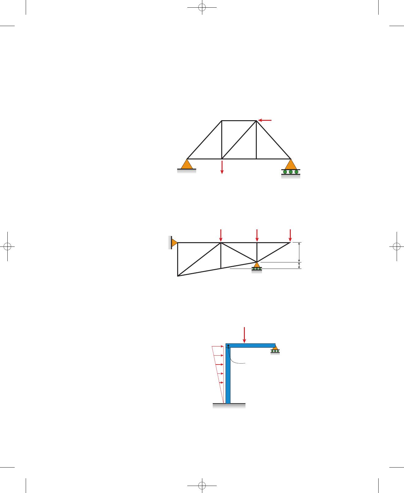
A-1.1: A plane truss has downward applied load Pat joint 2 and another
load Papplied leftward at joint 5. The force in member 3–5 is:
(A) 0
(B)
(C)
(D) ⫹1.5 P
⫺P
⫺P/2
996
ABCD
G
E
F
3 m
4.5 m
3 m
15 kN 5 kN
3 m
1 m
10 kN
3 m
B
C
A
900 N
3 m
4 m
Pin
connection
1200 N/m 1.2 m
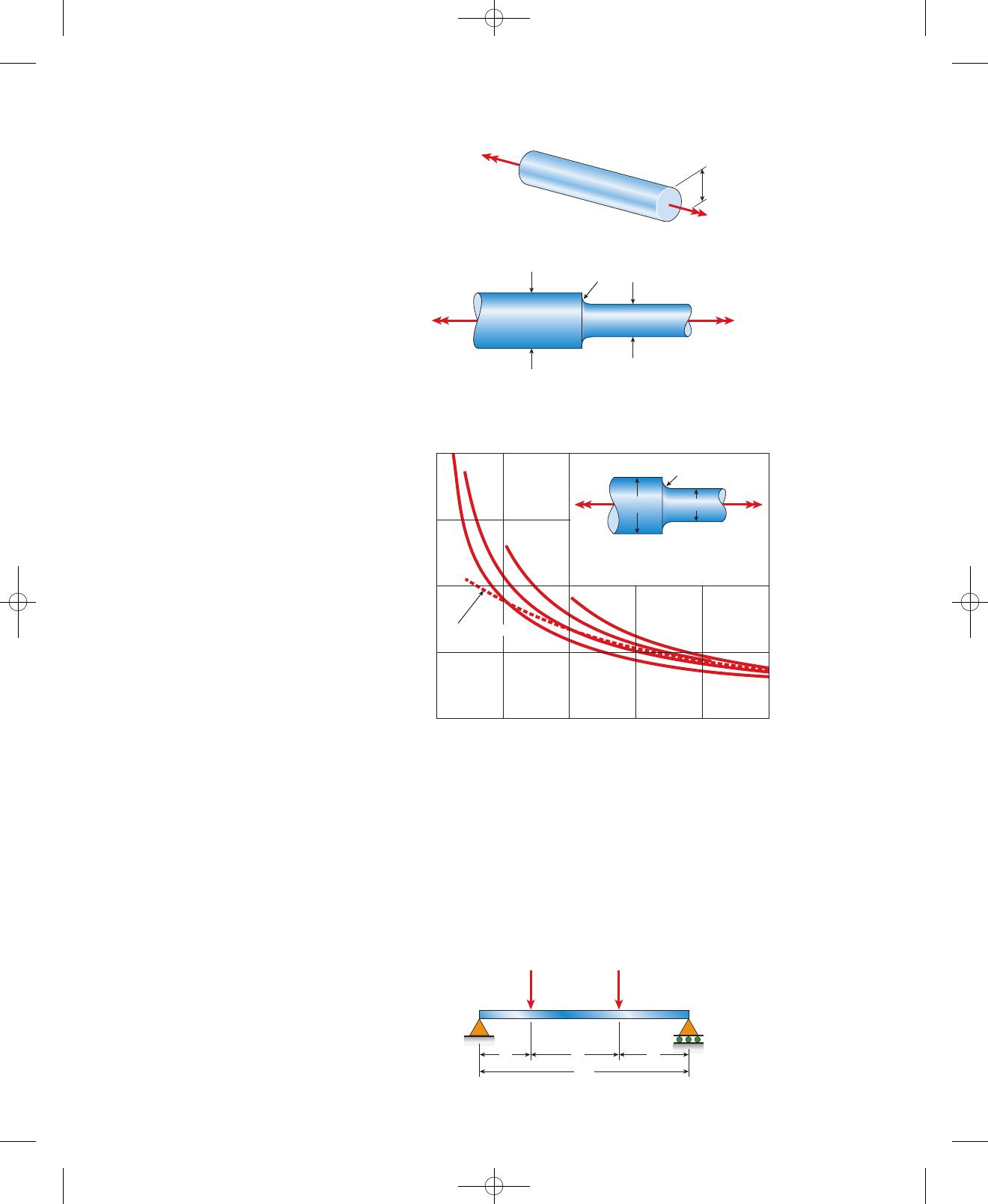
A-1.2: The force in member FE of the plane truss below is approximately:
(A)
(B)
(C) 3.9 kN
(D) 4.7 kN
⫺2.2 kN
⫺1.5 kN
A-1.3: The moment reaction at Ain the plane frame below is approximately:
(A)
(B)
(C)
(D) ⫹6400 N #m
⫺3600 N #m
⫺2280 N #m
⫹1400 N #m
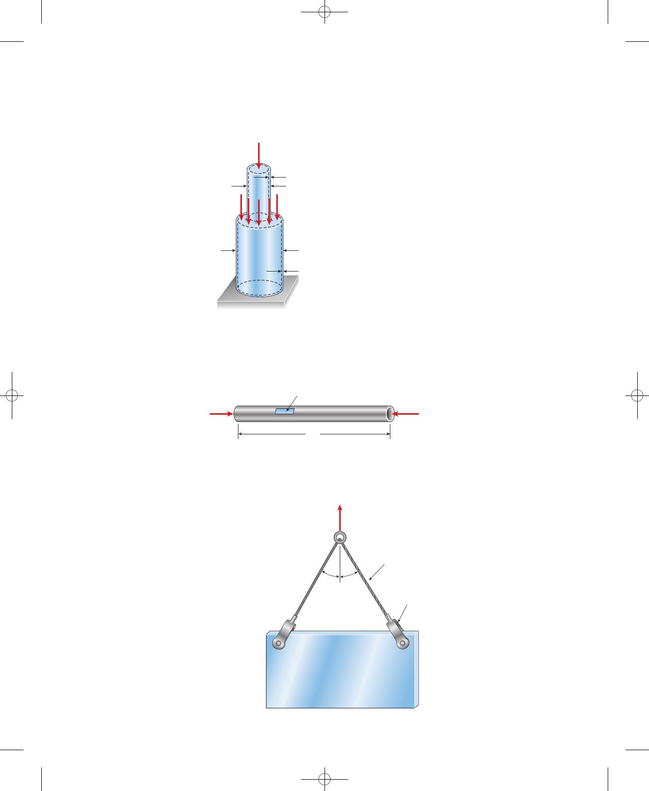
A-1.4: A hollow circular post ABC (see figure) supports a load
acting at the top. A second load P2is uniformly distributed
around the cap plate at B. The diameters and thicknesses of the upper and
lower parts of the post are , , ,dBC ⫽60 mmdAB ⫽30 mm tAB ⫽12 mm
P1⫽16 kN
P
P
L
LL
L
L
16
24
53
77735_14_appA_p995-1036.qxd:77735_14_appA_p995-1036.qxd 10/21/11 9:42 AM Page 996
Appendix A FE Exam Review Problems 997
A
B
C
P1
dAB
tAB
dB
C
tBC
P2
and , respectively. The lower part of the post must have the
same compressive stress as the upper part. The required magnitude of the
load P2is approximately:
(A) 18 kN
(B) 22 kN
(C) 28 kN
(D) 46 kN
tBC ⫽9mm
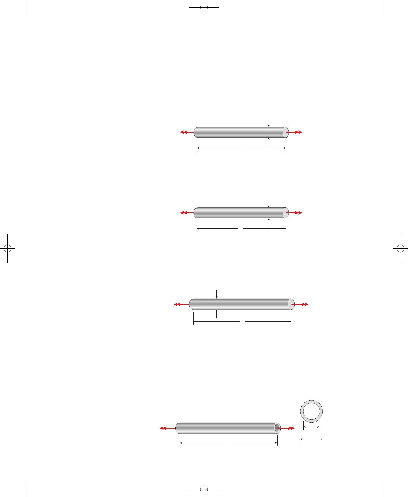
A-1.5: A circular aluminum tube of length is loaded in com-
pression by forces P. The outside and inside diameters are 80 mm and
68 mm, respectively. A strain gage on the outside of the bar records a nor-
mal strain in the longitudinal direction of . The shortening of
the bar is approximately:
(A) 0.12 mm
(B) 0.26 mm
(C) 0.36 mm
(D) 0.52 mm
400 ⫻10⫺6
L⫽650 mm
A-1.6: A steel plate weighing 27 kN is hoisted by a cable sling that has a
clevis at each end. The pins through the clevises are 22 mm in diameter.
Each half of the cable is at an angle of 35⬚to the vertical. The average
shear stress in each pin is approximately:
(A) 22 MPa
(B) 28 MPa
(C) 40 MPa
(D) 48 MPa
Strain gage
L
P
P
35°
35°
Clevis
Cable sling
P
Steel plate
77735_14_appA_p995-1036.qxd:77735_14_appA_p995-1036.qxd 10/21/11 9:42 AM Page 997
Appendix A FE Exam Review Problems
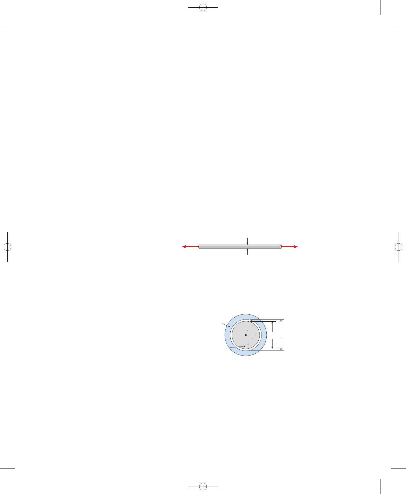
A-1.7: A steel wire hangs from a high-altitude balloon. The steel has unit
weight 77 kN/m3and yield stress of 280 MPa. The required factor of
safety against yield is 2.0. The maximum permissible length of the wire is
approximately:
(A) 1800 m
(B) 2200 m
(C) 2600 m
(D) 3000 m
A-1.8: An aluminum bar of diameter 50 mm
cannot exceed a diameter of 50.1 mm when compressed by axial force P.
The maximum acceptable compressive load Pis approximately:
(A) 190 kN
(B) 200 kN
(C) 470 kN
(D) 860 kN
A-1.9: An aluminum bar of diameter 20 mm is
stretched by axial forces P, causing its diameter to decrease by 0.022 mm.
The load Pis approximately:
(A) 73 kN
(B) 100 kN
(C) 140 kN
(D) 339 kN
(E⫽70 GPa, v⫽0.33)
(E⫽72 GPa, v⫽0.33)
998
dPP
A-1.10: An polyethylene bar of diameter 80 mm
is inserted in a steel tube of inside diameter 80.2 mm and then compressed
by axial force P. The gap between steel tube and polyethylene bar will
close when compressive load Pis approximately:
(A) 18 kN
(B) 25 kN
(C) 44 kN
(D) 60 kN
(E⫽1.4 GPa, v⫽0.4)
d2
d1
Steel
tube
Polyethylene
bar
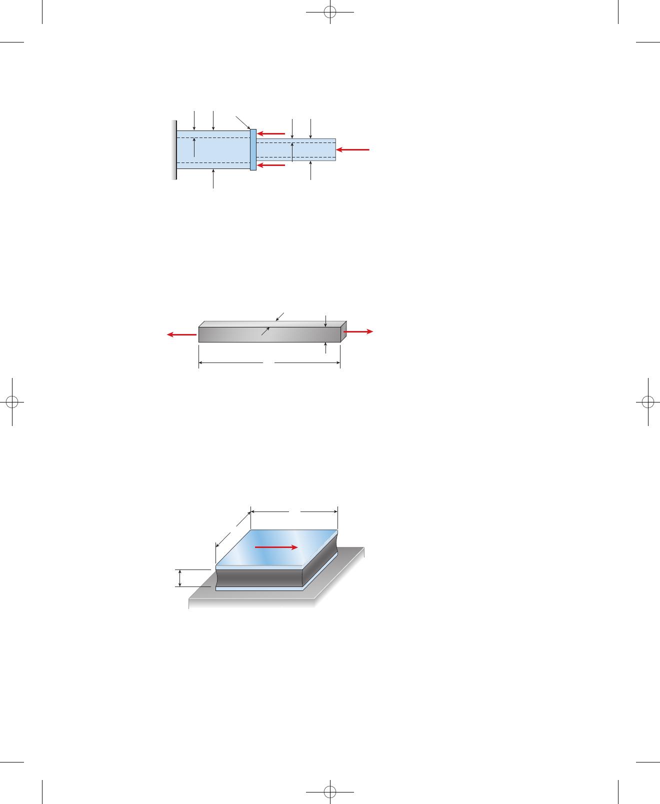
A-1.11: A pipe carries a load at Aand a
uniformly distributed load on the cap plate at B. Initial pipe
diameters and thicknesses are , ,
, and . Under loads P1and P2, wall thickness
tBC increases by 0.0036 mm. Poisson’s ratio for the pipe material is
approximately:
(A) 0.27
(B) 0.30
(C) 0.31
(D) 0.34
ν
dBC ⫽70 mm tBC ⫽10 mm
dAB ⫽38 mm tAB ⫽12 mm
P2⫽100 kN
(E⫽110 GPa) P1⫽120 kN
77735_14_appA_p995-1036.qxd:77735_14_appA_p995-1036.qxd 10/21/11 9:42 AM Page 998
Appendix A FE Exam Review Problems 999
P2
dAB
tAB
dBC
tBC
AB
CCap plate
P1
A-1.12: A titanium bar with square cross sec-
tion and length is subjected to tensile load
. The increase in volume of the bar is approximately:
(A) 1400 mm3
(B) 3500 mm3
(C) 4800 mm3
(D) 9200 mm3
P⫽900 kN
(b⫽75 mm) L⫽3.0 m
(E⫽100 GPa, v⫽0.33)
A-1.13: An elastomeric bearing pad is subjected to a shear force Vduring a
static loading test. The pad has dimensions and ,
and thickness . The lateral displacement of the top plate with
respect to the bottom plate is 14 mm under a load . The shear
modulus of elasticity Gof the elastomer is approximately:
(A) 1.0 MPa
(B) 1.5 MPa
(C) 1.7 MPa
(D) 1.9 MPa
t⫽55 mm
a⫽150 mm b⫽225 mm
P⫽16 kN
b
b
P
L
P
a
b
V
t
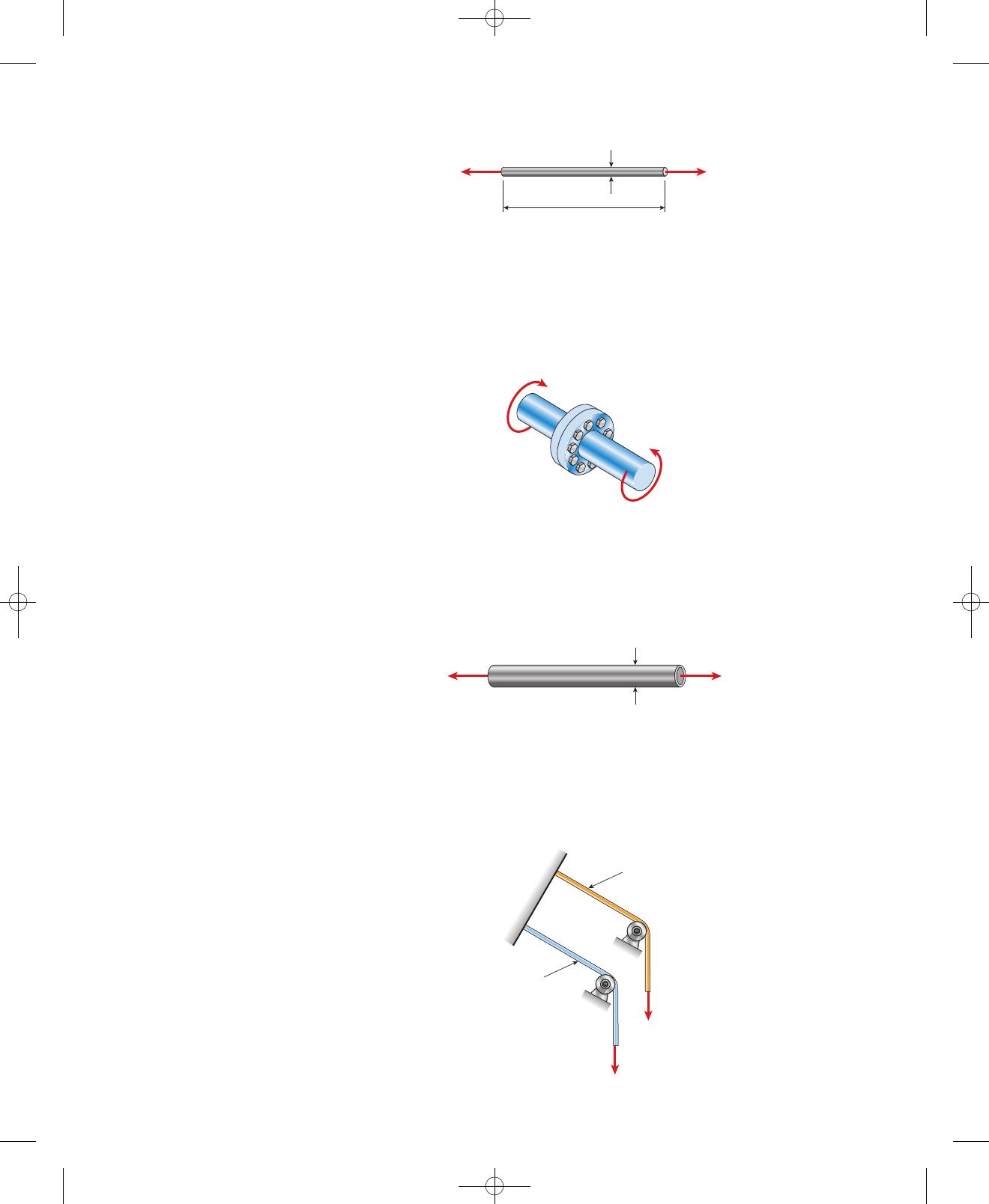
A-1.14: A bar of diameter and length is loaded
in tension by forces P. The bar has modulus and allowable
normal stress of 180 MPa. The elongation of the bar must not exceed
2.7 mm. The allowable value of forces Pis approximately:
(A) 41 kN
(B) 46 kN
(C) 56 kN
(D) 63 kN
E⫽45 GPa
d⫽18 mm L⫽0.75 m
77735_14_appA_p995-1036.qxd:77735_14_appA_p995-1036.qxd 10/21/11 9:42 AM Page 999
Appendix A FE Exam Review Problems
1000
d
PP
L
A-1.15: Two flanged shafts are connected by eight 18-mm bolts. The diam-
eter of the bolt circle is 240 mm. The allowable shear stress in the bolts is
90 MPa. Ignore friction between the flange plates. The maximum value of
torque T0is approximately:
(A) 19 kN⭈m
(B) 22 kN⭈m
(C) 29 kN⭈m
(D) 37 kN⭈m
A-1.16: A copper tube with wall thickness of 8 mm must carry an axial ten-
sile force of 175 kN. The allowable tensile stress is 90 MPa. The minimum
required outer diameter is approximately:
(A) 60 mm
(B) 72 mm
(C) 85 mm
(D) 93 mm
T0
T0
PP
d
A-2.1: Two wires, one copper and the other steel, of equal length stretch
the same amount under an applied load P. The moduli of elasticity for
each is and . The ratio of the diameter of
the copper wire to that of the steel wire is approximately:
(A) 1.00
(B) 1.08
(C) 1.19
(D) 1.32
Es⫽210 GPa Ec⫽120 GPa
P
Steel
wire
P
Copper
wire
77735_14_appA_p995-1036.qxd:77735_14_appA_p995-1036.qxd 10/21/11 9:42 AM Page 1000
Appendix A FE Exam Review Problems 1001
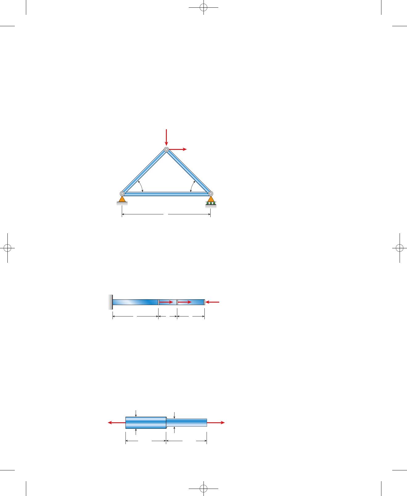
A-2.2: A plane truss with span length is constructed using cast
iron pipes with a cross-sectional area of 4500 mm2. The
displacement of joint Bcannot exceed 2.7 mm. The maximum value of
loads Pis approximately:
(A) 340 kN
(B) 460 kN
(C) 510 kN
(D) 600 kN
(E⫽170 GPa)
L⫽4.5 m
L
AB
45° 45°
P
P
C
a b c
B
P1P2
P3
ACD
d1
P
d2
L/2 L/2
P
A-2.3: A brass rod with a cross-sectional area of 250 mm2
is loaded by forces , , and . Segment
lengths of the bar are , , and . The
change in length of the bar is approximately:
(A) 0.9 mm
(B) 1.6 mm
(C) 2.1 mm
(D) 3.4 mm
a⫽2.0 m b⫽0.75 m c⫽1.2 m
P1⫽15 kN P2⫽10 kN P3⫽8kN
(E⫽110 GPa)
A-2.4: A brass bar of length has diameter
over one-half of its length and diameter over
the other half. Compare this nonprismatic bar to a prismatic bar of the
same volume of material with constant diameter dand length L. The elon-
gation of the prismatic bar under the same load is approxi-
mately:
(A) 3 mm
(B) 4 mm
(C) 5 mm
(D) 6 mm
P⫽25 kN
d1⫽18 mm d2⫽12 mm
(E⫽110 MPa) L⫽2.5 m
77735_14_appA_p995-1036.qxd:77735_14_appA_p995-1036.qxd 10/21/11 9:42 AM Page 1001
Appendix A FE Exam Review Problems
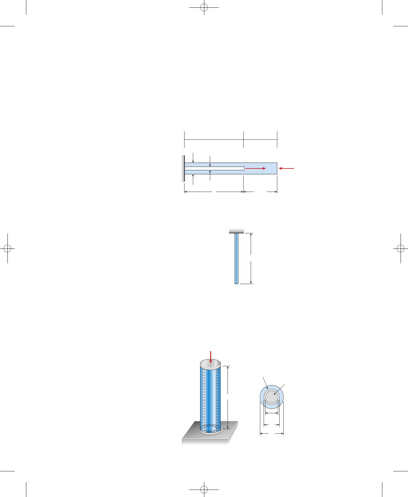
A-2.5: A nonprismatic cantilever bar has an internal cylindrical hole of
diameter d/2 from 0 to x, so the net area of the cross section for Segment 1
is (3/4)A. Load Pis applied at x, and load is applied at .
Assume that Eis constant. The length of the hollow segment, x, required
to obtain axial displacement at the free end is:
(A)
(B)
(C)
(D) x⫽3L/5
x⫽L/3
x⫽L/4
x⫽L/5
δ⫽PL/EA
⫺P/2 x⫽L
1002
A-2.6: A nylon bar with diameter 12 mm, length 4.5 m,
and weight 5.6 N hangs vertically under its own weight. The elongation of
the bar at its free end is approximately:
(A) 0.05 mm
(B) 0.07 mm
(C) 0.11 mm
(D) 0.17 mm
(E⫽2.1 GPa)
A-2.7: A monel shell encloses
a brass core . Initially, both shell and core are
a length of 100 mm. A load Pis applied to both shell and core through
a cap plate. The load Prequired to compress both shell and core by
0.10 mm is approximately:
(A) 10.2 kN
(B) 13.4 kN
(C) 18.5 kN
(D) 21.0 kN
(Eb⫽96 GPa, d1⫽6 mm)
(Em⫽170 GPa, d3⫽12 mm, d2⫽8 mm)
23
dA
Segment 1 Segment 2
d
2
—
P
2
—
A
3
4
—
L – xx
P
L
B
A
P
Monel shell
Brass core
d3
d1
d2
L
77735_14_appA_p995-1036.qxd:77735_14_appA_p995-1036.qxd 10/21/11 9:42 AM Page 1002
Appendix A FE Exam Review Problems 1003
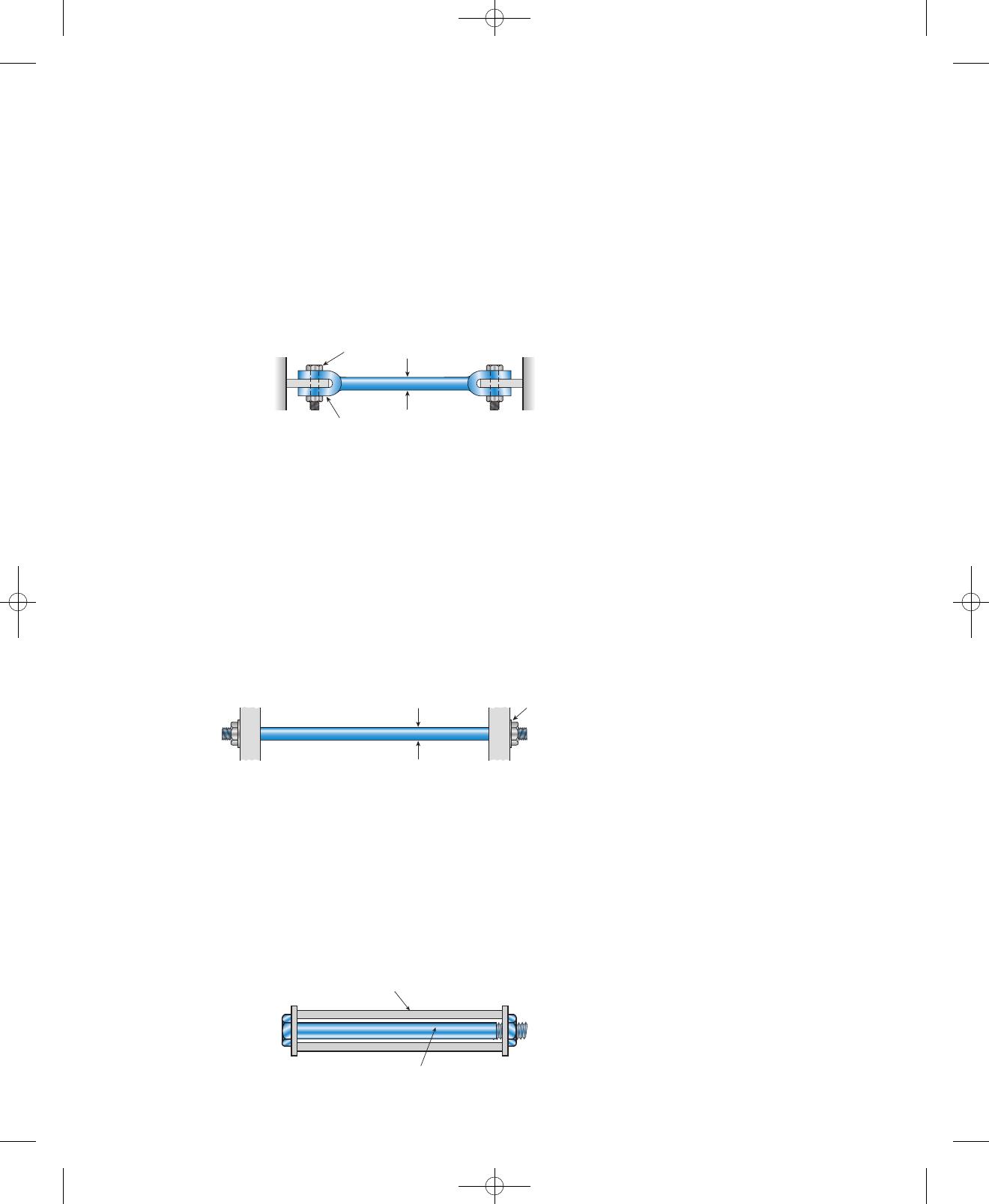
A-2.8: A steel rod
is held stress-free between rigid walls by a clevis
and pin assembly at each end. If the allowable shear
stress in the pin is 45 MPa and the allowable normal stress in the rod is 70
MPa, the maximum permissible temperature drop ⌬Tis approximately:
(A) 14 ⬚C
(B) 20 ⬚C
(C) 28 ⬚C
(D) 40 ⬚C
ctes⫽12 ⫻10⫺6/°C)
(Es⫽210 GPa, dr⫽12 mm,
(dp⫽15 mm)
A-2.9: A threaded steel rod
is held stress-free between rigid walls by a nut and
washer assembly at each end. If the allowable bearing
stress between the washer and wall is 55 MPa and the allowable normal
stress in the rod is 90 MPa, the maximum permissible temperature drop
⌬Tis approximately:
(A) 25 ⬚C
(B) 30 ⬚C
(C) 38 ⬚C
(D) 46 ⬚C
(Es⫽210 GPa, dr⫽15 mm,
(dw⫽22 mm)
ctes⫽12 ⫻10⫺6/°C.)
A-2.10: A steel bolt is enclosed by a
copper tube and the
end nut is turned until it is just snug. The pitch of the bolt threads is
1.25 mm. The bolt is now tightened by a quarter turn of the nut. The
resulting stress in the bolt is approximately:
(A) 56 MPa
(B) 62 MPa
(C) 74 MPa
(D) 81 MPa
(length ⫽0.5 m, area ⫽400 mm2,Ec⫽110 GPa)
(area ⫽130 mm2,Es⫽210 GPa)
Rod, dr
Pin, dp
Clevis
ΔT
Rod, drWasher, dw
ΔT
Steel bolt
Copper tube
77735_14_appA_p995-1036.qxd:77735_14_appA_p995-1036.qxd 10/21/11 9:42 AM Page 1003
Appendix A FE Exam Review Problems
1004
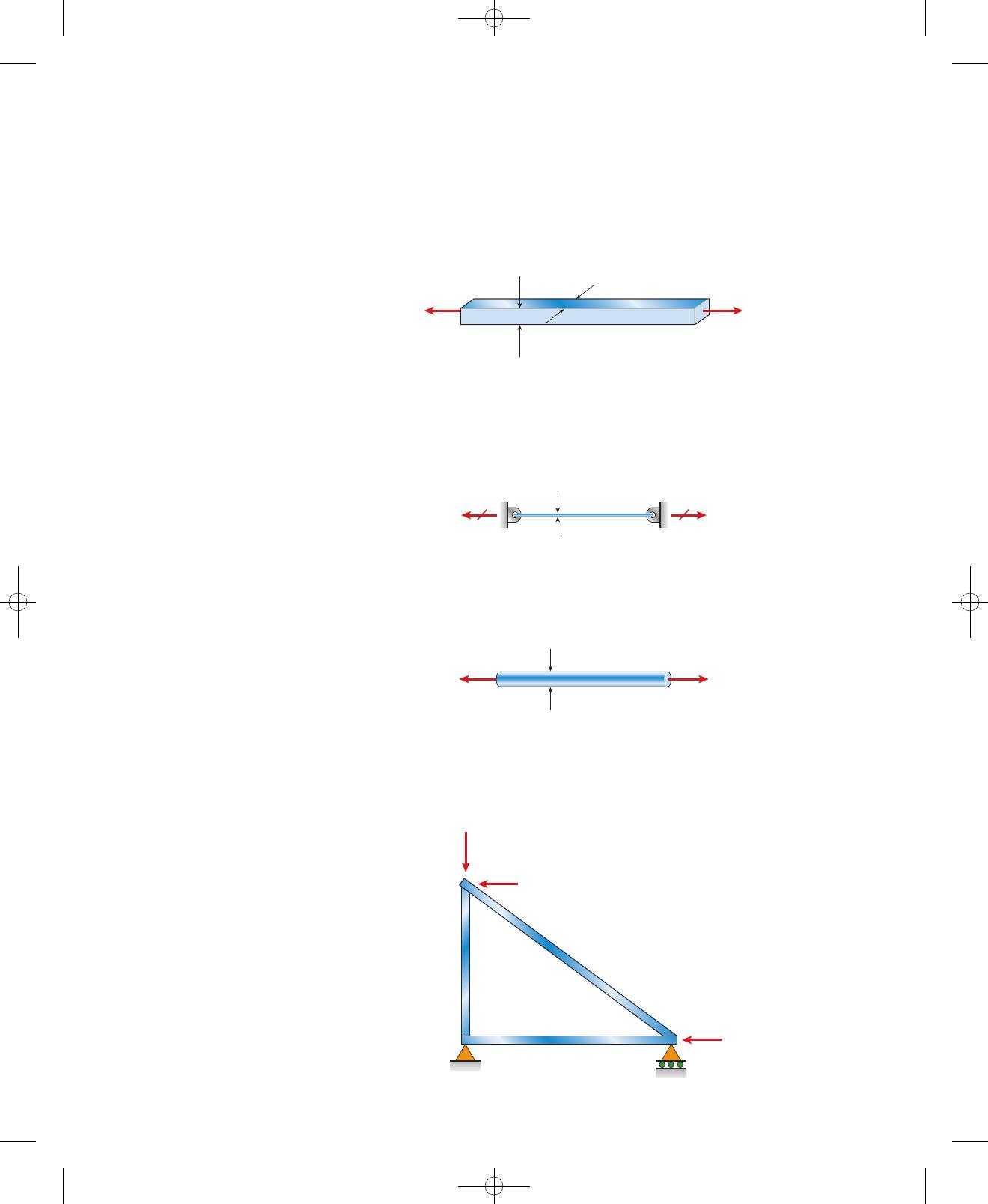
A-2.11: A steel bar of rectangular cross section
carries a tensile load P. The allowable stresses in tension and shear are
100 MPa and 48 MPa, respectively. The maximum permissible load Pmax is
approximately:
(A) 56 kN
(B) 62 kN
(C) 74 kN
(D) 91 kN
(a⫽38 mm, b⫽50 mm)
A-2.12: A brass wire is pretensioned to
. The coefficient of thermal expansion for the wire is
. The temperature change at which the wire goes slack is
approximately:
(A)
(B)
(C)
(D) ⫺18.2 °C
⫹12.6 °C
⫺12.6 °C
⫹5.7 °C
19.5 ⫻10⫺6/°C
T⫽85 N
(d⫽2.0 mm, E⫽110 GPa)
A-2.13: A copper bar is loaded by tensile load
. The maximum shear stress in the bar is approximately:
(A) 73 MPa
(B) 87 MPa
(C) 145 MPa
(D) 150 MPa
P⫽11.5 kN
(d⫽10 mm, E⫽110 GPa)
A-2.14: A steel plane truss is loaded at Band Cby forces .
The cross-sectional area of each member is . Truss dimen-
sions are and . The maximum shear stress in bar AB is
approximately:
(A) 27 MPa
(B) 33 MPa
(C) 50 MPa
(D) 69 MPa
H⫽3m L⫽4m
A⫽3970 mm2
P⫽200 kN
PP
a
b
TdT
PP d
H
P
P
P
C
A
B
L
77735_14_appA_p995-1036.qxd:77735_14_appA_p995-1036.qxd 10/21/11 9:42 AM Page 1004
Appendix A FE Exam Review Problems 1005
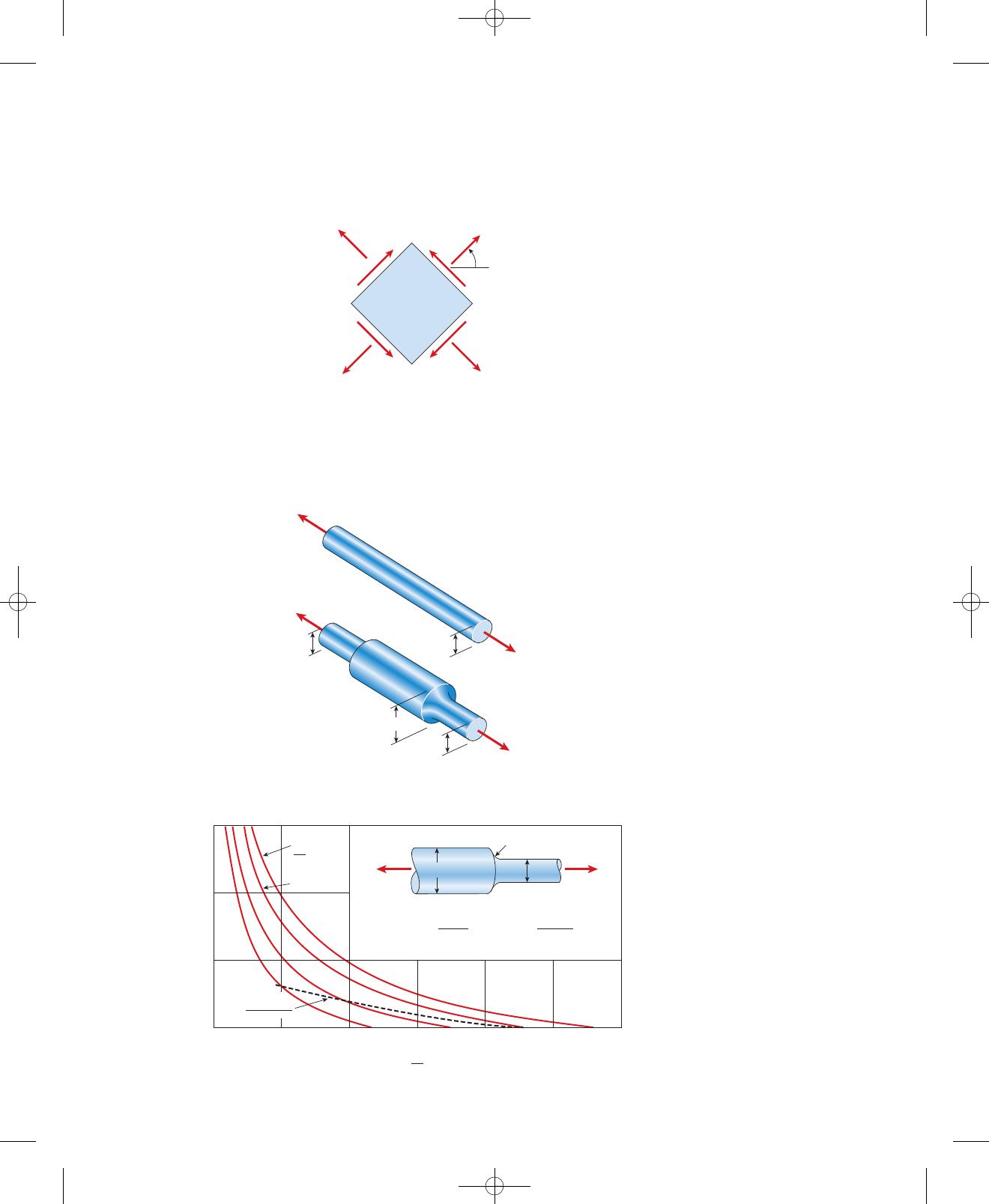
A-2.15: A plane stress element on a bar in uniaxial stress has a tensile stress
of (see fig.). The maximum shear stress in the bar is
approximately:
(A) 29 MPa
(B) 37 MPa
(C) 50 MPa
(D) 59 MPa
σθ⫽78 MPa
A-2.16: A prismatic bar (diameter ) is loaded by force P1.
A stepped bar (diameters and with radius of
fillets ) is loaded by force P2. The allowable axial stress in the
material is 75 MPa. The ratio of the maximum permissible loads
that can be applied to the bars, considering stress concentration effects in
the stepped bar, is:
(A) 0.9
(B) 1.2
(C) 1.4
(D) 2.1
P1/P2
R⫽2mm
d1⫽20 mm d2⫽25 mm
d0⫽18 mm
συ/2
υ
τυτυ
τυτυ
συ
K
0 0.05 0.10
1.1
1.2
1.5
0.15 0.20 0.25 0.30
3.0
2.5
2.0
1.5
R
D1
K = P
1/4 D2
max
nom
nom =
D2 – D1
2
R =
= 2 P
R
P
D1
D2
D1D2
σ
σσ
π
FIG. 2-66 Stress-concentration factor Kfor round bars with shoulder fillets.
The dashed line is for a full quarter-circular fillet.
P1
P2
d1
d0
d1
d2
P2
P1
77735_14_appA_p995-1036.qxd:77735_14_appA_p995-1036.qxd 10/21/11 9:42 AM Page 1005
Appendix A FE Exam Review Problems
1006
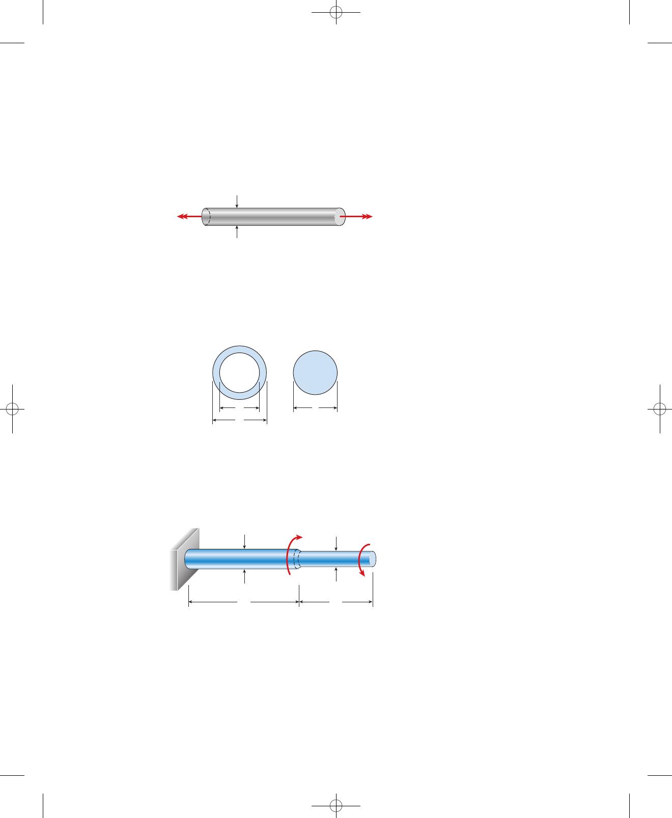
A-3.1: A brass rod of length is twisted by torques Tuntil the
angle of rotation between the ends of the rod is 3.5⬚. The allowable shear
strain in the copper is 0.0005 rad. The maximum permissible diameter of
the rod is approximately:
(A) 6.5 mm
(B) 8.6 mm
(C) 9.7 mm
(D) 12.3 mm
L⫽0.75 m
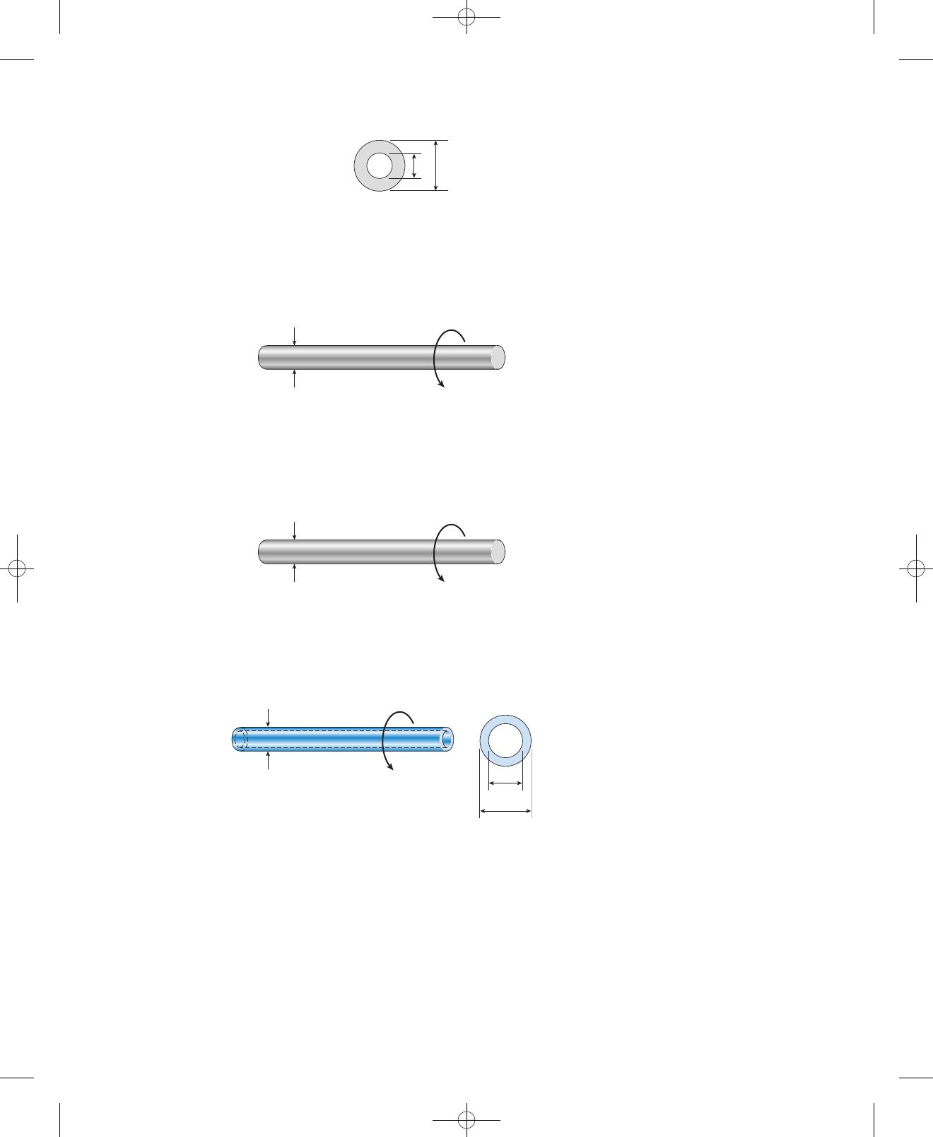
A-3.2: The angle of rotation between the ends of a nylon bar is 3.5⬚. The
bar diameter is 70 mm and the allowable shear strain is 0.014 rad. The
minimum permissible length of the bar is approximately:
(A) 0.15 m
(B) 0.27 m
(C) 0.40 m
(D) 0.55 m
A-3.3: A brass bar twisted by torques Tacting at the ends has the follow-
ing properties: , , and . The torsional
stiffness of the bar is approximately:
(A) 1200 N⭈m
(B) 2600 N⭈m
(C) 4000 N⭈m
(D) 4800 N⭈m
L⫽2.1 m d⫽38 mm G⫽41 GPa
A-3.4: A brass pipe is twisted by torques acting at the ends
causing an angle of twist of 3.5⬚. The pipe has the following properties:
, , and . The shear modulus of elas-
ticity Gof the pipe is approximately:
(A) 36.1 GPa
(B) 37.3 GPa
(C) 38.7 GPa
(D) 40.6 GPa
L⫽2.1 m d1⫽38 mm d2⫽56 mm
T⫽800 N #m
L
d
TT
L
d
TT
L
d
TT
d2
d1
L
TT
77735_14_appA_p995-1036.qxd:77735_14_appA_p995-1036.qxd 10/21/11 9:42 AM Page 1006
Appendix A FE Exam Review Problems 1007
T1
dT1
d2
d1d
A-3.5: An aluminum bar of diameter is twisted by torques T1
at the ends. The allowable shear stress is 65 MPa. The maximum permis-
sible torque T1is approximately:
(A) 1450 N⭈m
(B) 1675 N⭈m
(C) 1710 N⭈m
(D) 1800 N⭈m
d⫽52 mm
A-3.6: A steel tube with diameters and is
twisted by torques at the ends. The diameter of a solid steel shaft that
resists the same torque at the same maximum shear stress is approxi-
mately:
(A) 56 mm
(B) 62 mm
(C) 75 mm
(D) 82 mm
d2⫽86 mm d1⫽52 mm
A-3.7: A stepped steel shaft with diameters and
is twisted by torques and acting in
opposite directions. The maximum shear stress is approximately:
(A) 54 MPa
(B) 58 MPa
(C) 62 MPa
(D) 79 MPa
T1⫽3.5 kN #mT2⫽1.5 kN #m
d1⫽56 mm d2⫽52 mm
L1
d1
T1T2
L2
BC
d2
A
A-3.8: A stepped steel shaft with diameters
and is twisted by torques Tat each end. Segment lengths are
and . If the allowable shear stress is 28 MPa and
maximum allowable twist is 1.8⬚, the maximum permissible torque is
approximately:
(A) 142 N⭈m
(B) 180 N⭈m
(C) 185 N⭈m
(D) 257 N⭈m
L1⫽0.9 m L2⫽0.75 m
d2⫽32 mm
(G⫽75 GPa) d1⫽36 mm
77735_14_appA_p995-1036.qxd:77735_14_appA_p995-1036.qxd 10/21/11 9:43 AM Page 1007
Appendix A FE Exam Review Problems
1008
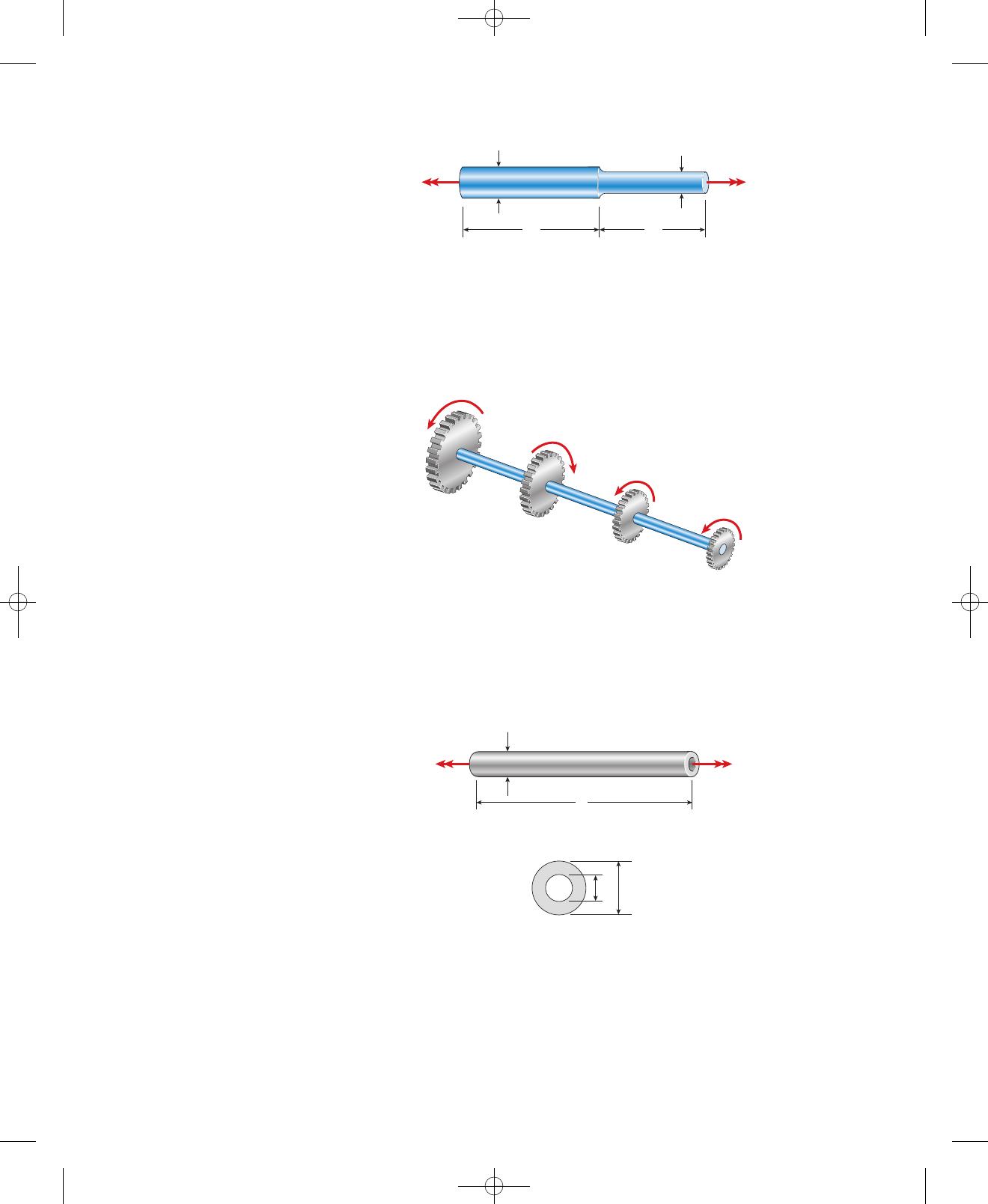
A-3.9: A gear shaft transmits torques , ,
, and . If the allowable shear stress is
50 MPa, the required shaft diameter is approximately:
(A) 38 mm
(B) 44 mm
(C) 46 mm
(D) 48 mm
TC⫽650 N #mTD⫽825 N #m
TA⫽975 N #mTB⫽1500 N #m
A-3.10: A hollow aluminum shaft
has an angle of twist per unit length of 1.8⬚/m due to
torques T. The resulting maximum tensile stress in the shaft is approx-
imately:
(A) 38 MPa
(B) 41 MPa
(C) 49 MPa
(D) 58 MPa
(G⫽27 GPa, d2⫽96 mm,
and d1⫽52 mm)
C
D
A
B
TA
TB
TC
TD
L
d2
d1
d2
TT
A-3.11: Torques are applied to a hollow aluminum shaft
. The allowable shear stress is 45 MPa
and the allowable normal strain is . The required outside
diameter d2of the shaft is approximately:
(A) 38 mm
(B) 56 mm
(C) 87 mm
(D) 91 mm
T⫽5.7 kN #m
8.0 ⫻10⫺4
(G⫽27 GPa and d1⫽52 mm)
L1L2
T
AB
C
d1d2T
77735_14_appA_p995-1036.qxd:77735_14_appA_p995-1036.qxd 10/21/11 9:43 AM Page 1008
Appendix A FE Exam Review Problems 1009
A-3.12: A motor drives a shaft with diameter at
and delivers of power. The maximum shear stress in the shaft
is approximately:
(A) 32 MPa
(B) 40 MPa
(C) 83 MPa
(D) 91 MPa
f⫽5.25 Hz
P⫽25 kW
d⫽46 mm
d
f
P
A-3.13: A motor drives a shaft at and delivers of
power. The allowable shear stress in the shaft is 45 MPa. The minimum
diameter of the shaft is approximately:
(A) 35 mm
(B) 40 mm
(C) 47 mm
(D) 61 mm
f⫽10 Hz P⫽35 kW
d
f
P
d2
d1
A-3.14: A drive shaft running at 2500 rpm has outer diameter 60 mm and
inner diameter 40 mm. The allowable shear stress in the shaft is 35 MPa.
The maximum power that can be transmitted is approximately:
(A) 220 kW
(B) 240 kW
(C) 288 kW
(D) 312 kW
dn
d2
d1
A-3.15: A prismatic shaft (diameter ) is loaded by torque T1.
A stepped shaft (diameters and with radius of
fillets ) is loaded by torque T2. The allowable shear stress in the
material is 42 MPa. The ratio of the maximum permissible torques
that can be applied to the shafts, considering stress concentration effects
in the stepped shaft is:
(A) 0.9
(B) 1.2
(C) 1.4
(D) 2.1
T1/T2
d1⫽20 mm d2⫽25 mm
d0⫽19 mm
R⫽2mm
77735_14_appA_p995-1036.qxd:77735_14_appA_p995-1036.qxd 10/21/11 9:43 AM Page 1009
Appendix A FE Exam Review Problems
1010
FIG. 3-56 Stress-concentration factor Kfor a stepped shaft in torsion. (The
dashed line is for a full quarter-circular fillet.)
T1
T1
d0
R
T2T2
D2D1
K
0
1.00
1.50
2.00
0.10
1.5
1.2
1.1
0.20
D2D1
T
R
T
τmax = Kτnom τnom = 16T
D1
3
——
=2
D1
D2
—–
D1
R
—–
=+ 2R
D1
D2
π
AB
2PP
L
abc
A-4.1: A simply supported beam with proportional loading
has span length . Load Pis 1.2 m from support Aand load 2Pis
1.5 m from support B. The bending moment just left of load 2Pis approx-
imately:
(A) 5.7 kN⭈m
(B) 6.2 kN⭈m
(C) 9.1 kN⭈m
(D) 10.1 kN⭈m
(P⫽4.1 kN)
L⫽5m
77735_14_appA_p995-1036.qxd:77735_14_appA_p995-1036.qxd 10/21/11 9:43 AM Page 1010
Appendix A FE Exam Review Problems 1011
ACB
1.8 kN/m
7.5 kN
1.0 m 1.0 m
0.5 m
5.0 m
3.0 m
AB
1.8 kN/m
4.5 kN
1.0 m1.0 m 3.0 m
5.0 m 1.0 m
BA C
9 kN
4.5 kN
1.0 m
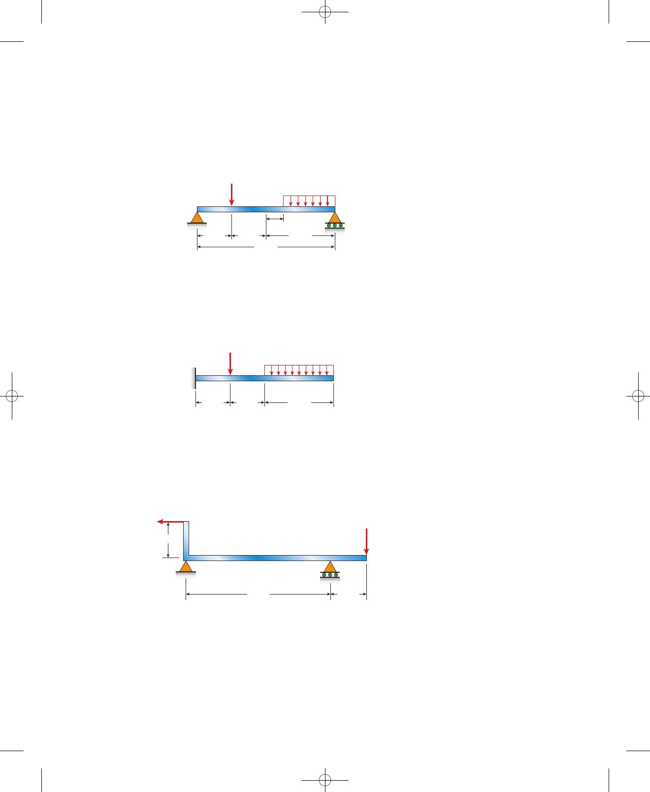
A-4.2: A simply supported beam is loaded as shown in the figure. The
bending moment at point Cis approximately:
(A) 5.7 kN⭈m
(B) 6.1 kN⭈m
(C) 6.8 kN⭈m
(D) 9.7 kN⭈m
A-4.3: A cantilever beam is loaded as shown in the figure. The bending
moment at 0.5 m from the support is approximately:
(A) 12.7 kN⭈m
(B) 14.2 kN⭈m
(C) 16.1 kN⭈m
(D) 18.5 kN⭈m
A-4.4: An L-shaped beam is loaded as shown in the figure. The bending
moment at the midpoint of span AB is approximately:
(A) 6.8 kN⭈m
(B) 10.1 kN⭈m
(C) 12.3 kN⭈m
(D) 15.5 kN⭈m
A-4.5: A T-shaped simple beam has a cable with force Panchored at B
and passing over a pulley at E, as shown in the figure. The bend-
ing moment just left of Cis 1.25 kN⭈m. The cable force Pis approxi-
mately:
(A) 2.7 kN
(B) 3.9 kN
(C) 4.5 kN
(D) 6.2 kN
77735_14_appA_p995-1036.qxd:77735_14_appA_p995-1036.qxd 10/21/11 9:43 AM Page 1011
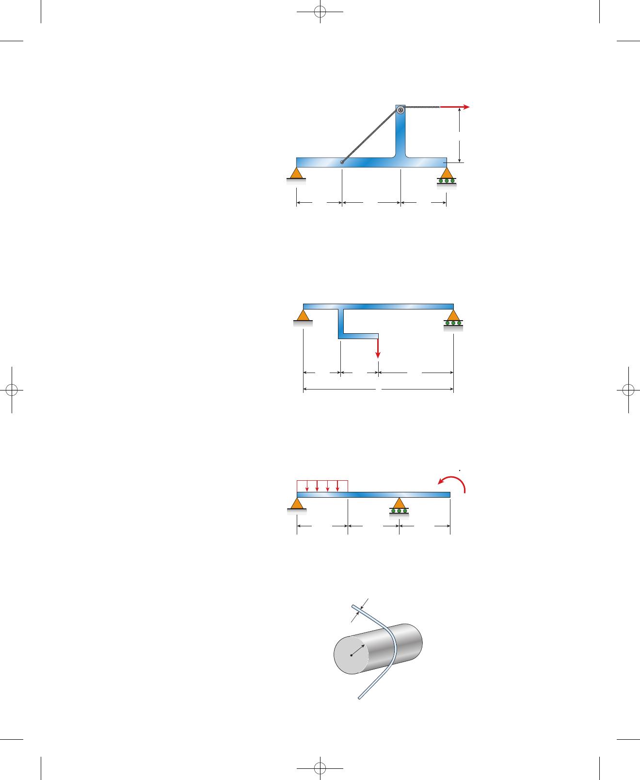
Appendix A FE Exam Review Problems
1012
A-4.6: A simple beam with attached bracket BDE has force
applied downward at E. The bending moment just right of Bis
approximately:
(A) 6 kN⭈m
(B) 10 kN⭈m
(C) 19 kN⭈m
(D) 22 kN⭈m
P⫽5kN
(L⫽9m)
A
EP
CDB
Cable
4 m
2 m 3 m 2 m
AC
L
DE
P
B
L
—
6
L
—
3
L
—
2
AC
B
1.6 m 1.6 m 1.6 m
4.5 kN m
15 kN/m
A-4.7: A simple beam AB with an overhang BC is loaded as shown in the
figure. The bending moment at the midspan of AB is approximately:
(A) 8 kN⭈m
(B) 12 kN⭈m
(C) 17 kN⭈m
(D) 21 kN⭈m
A-5.1: A copper wire is bent around a tube of radius
. The maximum normal strain in the wire is approximately:
(A)
(B)
(C)
(D) 1.92 ⫻10⫺3
1.76 ⫻10⫺3
R⫽0.6 m
(d⫽1.5 mm)
1.55 ⫻10⫺3
1.25 ⫻10⫺3
d
R
77735_14_appA_p995-1036.qxd:77735_14_appA_p995-1036.qxd 10/21/11 9:43 AM Page 1012
Appendix A FE Exam Review Problems 1013
A
L
B
q
h
b
s
L
d2
d1
A
BC
4 m 2 m
3 kN/m
z
y
C
20 mm
66.4 mm
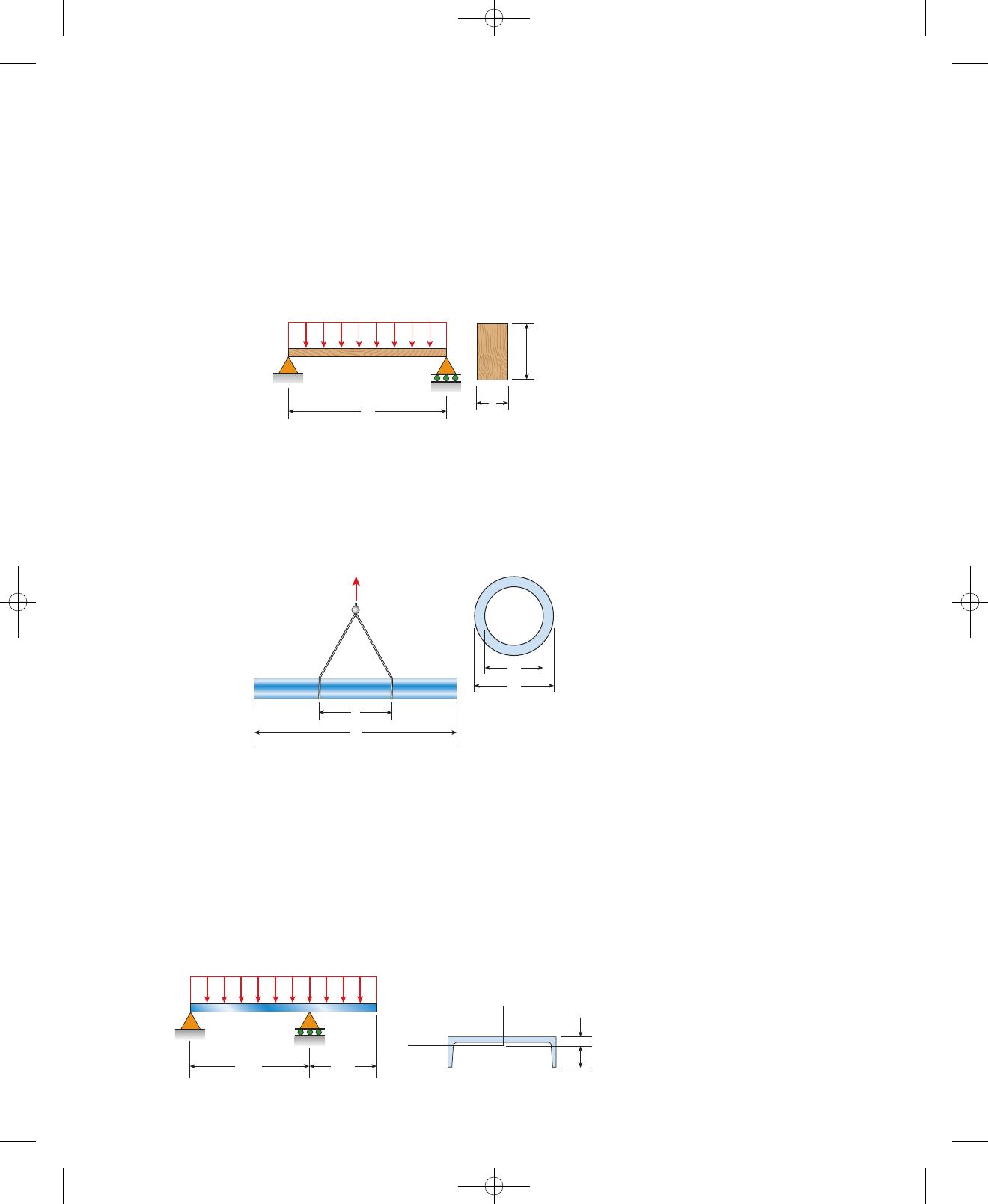
A-5.2: A simply supported wood beam with rectangular cross
section carries uniform load
includes the weight of the beam. The maximum flexural stress is
approximately:
(A) 8.7 MPa
(B) 10.1 MPa
(C) 11.4 MPa
(D) 14.3 MPa
(b⫽200 mm, h⫽280 mm)
(L⫽5m)
q⫽6.5 kN/m
A-5.3: A cast iron pipe
is lifted by a hoist. The lift points are
6 m apart. The maximum bending stress in the pipe is approximately:
(A) 28 MPa
(B) 33 MPa
(C) 47 MPa
(D) 59 MPa
(L⫽12 m, weight density ⫽72 kN/m3,
and d1⫽75 mm)d2⫽100 mm,
A-5.4: A beam with an overhang is loaded by a uniform load of 3 kN/m
over its entire length. Moment of inertia and
distances to top and bottom of the beam cross section are 20 mm and
66.4 mm, respectively. It is known that reactions at Aand Bare 4.5 kN
and 13.5 kN, respectively. The maximum bending stress in the beam is
approximately:
(A) 36 MPa
(B) 67 MPa
(C) 102 MPa
(D) 119 MPa
Iz⫽3.36 ⫻106mm4
77735_14_appA_p995-1036.qxd:77735_14_appA_p995-1036.qxd 10/21/11 9:43 AM Page 1013
Appendix A FE Exam Review Problems
1014
A-5.5: A steel hanger with solid cross section has horizontal force
applied at free end D. Dimension variable and
allowable normal stress is 150 MPa. Neglect self-weight of the hanger.
The required diameter of the hanger is approximately:
(A) 5 cm
(B) 7 cm
(C) 10 cm
(D) 13 cm
P⫽5.5 kN b⫽175 mm
6b
2b
AB
DC
P
2b
L
A
B
P
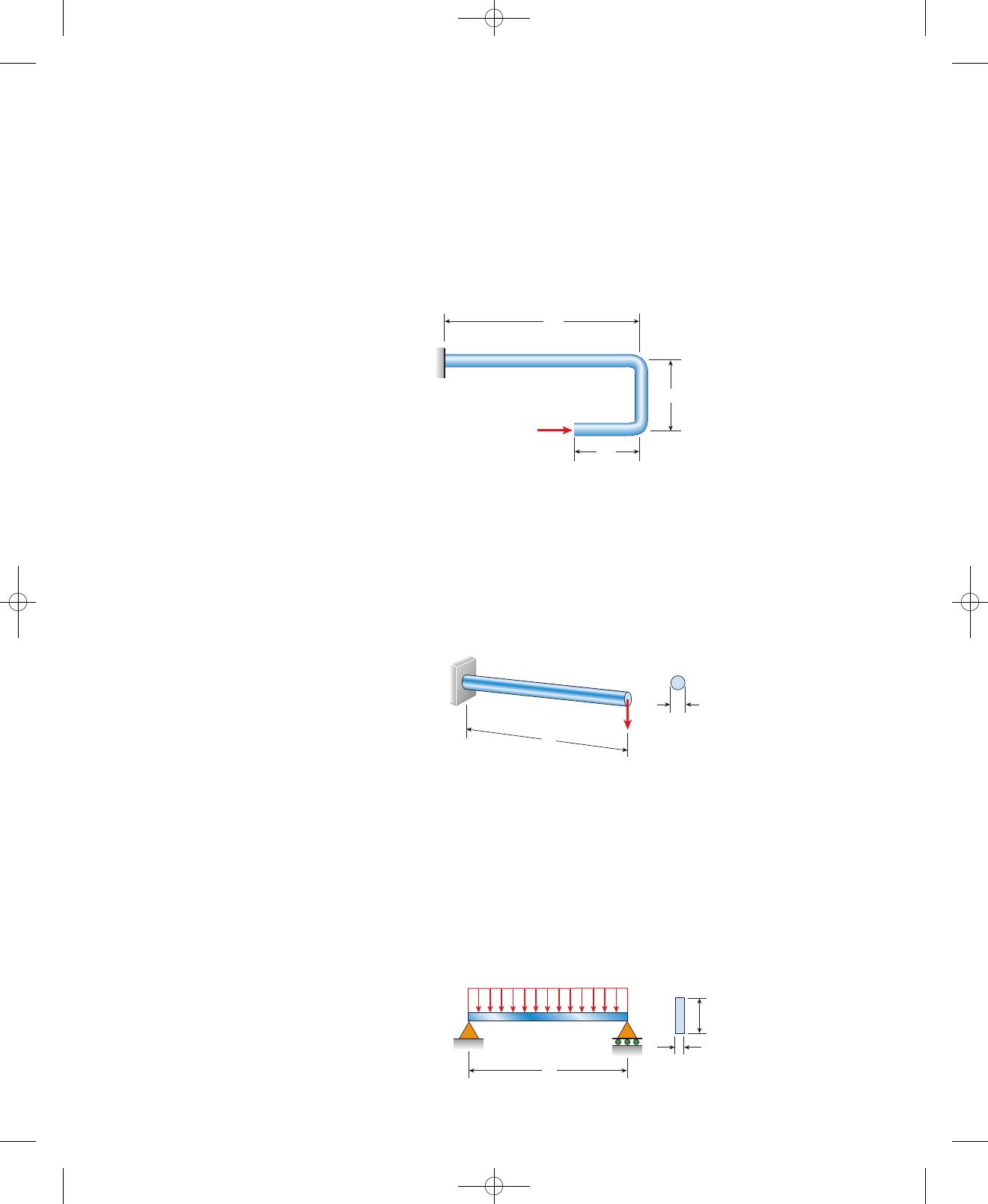
d
q
b
h
L
A-5.6: A cantilever wood pole carries force applied at its free
end, as well as its own weight . The length of
the pole is and the allowable bending stress is 14 MPa. The
required diameter of the pole is approximately:
(A) 4.2 cm
(B) 5.5 cm
(C) 6.1 cm
(D) 8.5 cm
P⫽300 N
L⫽0.75 m
(weight density ⫽6 kN/m3)
A-5.7: A simply supported steel beam of length and rectangu-
lar cross section carries a uniform load of
that includes its own weight. The maximum transverse
shear stress on the cross section at 0.25 m from the left support is approx-
imately:
(A) 20 MPa
(B) 24 MPa
(C) 30 MPa
(D) 36 MPa
L⫽1.5 m
q⫽48 kN/m
(h⫽75 mm, b⫽20 mm)
77735_14_appA_p995-1036.qxd:77735_14_appA_p995-1036.qxd 10/21/11 9:43 AM Page 1014
Appendix A FE Exam Review Problems 1015
36 mm
P at L/3
36 mm
12 mm
12 mm
12 mm
q
L
AB
q
L
q
2
—
1.2 m
235 mm
20 mm
W1 = 4300 N
W2 = 700 N
P1 = 1500 N
7.5 m
y
x
y
x
z
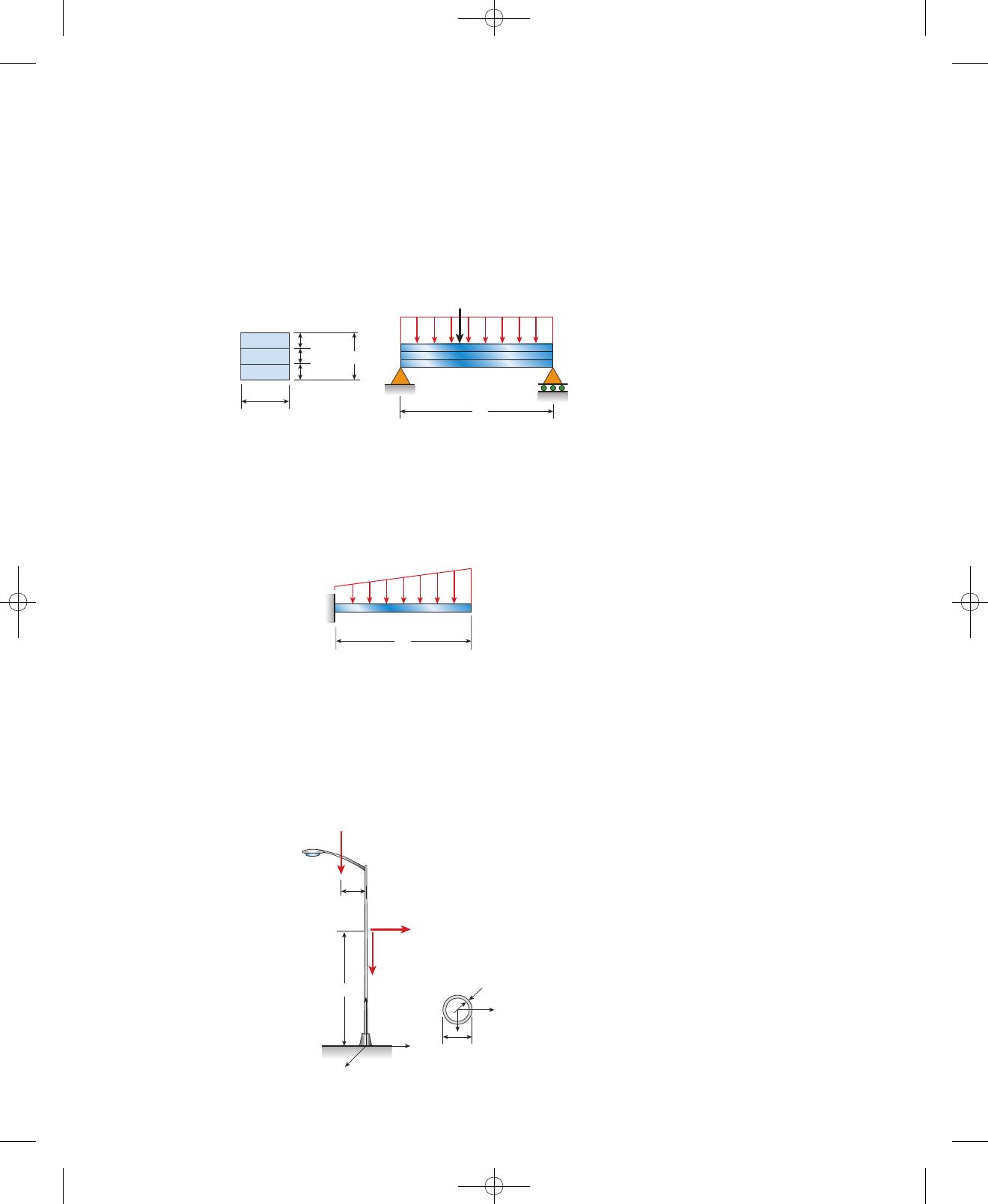
A-5.8: A simply supported laminated beam of length and
square cross section weighs 4.8 N. Three strips are glued together to form
the beam, with the allowable shear stress in the glued joint equal to
0.3 MPa. Considering also the weight of the beam, the maximum load P
that can be applied at L/3 from the left support is approximately:
(A) 240 N
(B) 360 N
(C) 434 N
(D) 510 N
L⫽0.5 m
A-5.9: An aluminum cantilever beam of length carries a
distributed load, which includes its own weight, of intensity q/2 at Aand
qat B. The beam cross section has a width of 50 mm and height of
170 mm. Allowable bending stress is 95 MPa and allowable shear stress is
12 MPa. The permissible value of load intensity qis approximately:
(A) 110 kN/m
(B) 122 kN/m
(C) 130 kN/m
(D) 139 kN/m
L⫽0.65 m
A-5.10: An aluminum light pole weighs 4300 N and supports an arm of
weight 700 N, with the arm center of gravity at 1.2 m left of the centroidal
axis of the pole. A wind force of 1500 N acts to the right at 7.5 m above
the base. The pole cross section at the base has an outside diameter of
235 mm and thickness of 20 mm. The maximum compressive stress at the
base is approximately:
(A) 16 MPa
(B) 18 MPa
(C) 21 MPa
(D) 24 MPa
77735_14_appA_p995-1036.qxd:77735_14_appA_p995-1036.qxd 10/21/11 9:43 AM Page 1015
Appendix A FE Exam Review Problems
1016
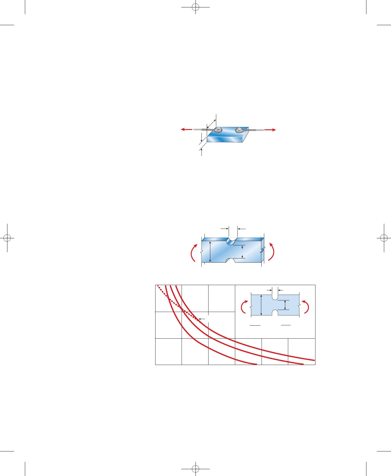
A-5.11: Two thin cables, each having a diameter of and carrying
tensile loads P, are bolted to the top of a rectangular steel block with
cross-sectional dimensions . The ratio of the maximum tensile to
compressive stress in the block due to loads P is:
(A) 1.5
(B) 1.8
(C) 2.0
(D) 2.5
d⫽t/6
b⫻t
b
t
PP
A-5.12: A rectangular beam with semicircular notches has dimen-
sions and . The maximum allowable bending
stress in the plastic beam is , and the bending moment
is . The minimum permissible width of the beam is:
(A) 12 mm
(B) 20 mm
(C) 28 mm
(D) 32 mm
M⫽185 N #m
σmax ⫽6.5 MPa
h⫽160 mm h1⫽140 mm
h
=
h1 + 2R
R
—
h1
3.0
2.5
2.0
1.5
0 0.05 0.10 0.15 0.20 0.25 0.30
K
1.05
= 1.2
1.1
b = thickness
K = σmax
σnom = 6M
bh
2
1
σnom
h1
h
MM
2R
h
h1
—
M
M
hh1
2R
FIG. 5-50 Stress-concentration factor Kfor a notched beam of rectangular
cross section in pure bending ( ; ,
perpendicular to the plane of the figure). The dashed line is for semicircular
notches .(h⫽h1⫹2R)
h⫽height of beam b⫽thickness of beam
77735_14_appA_p995-1036.qxd:77735_14_appA_p995-1036.qxd 10/21/11 9:43 AM Page 1016
Appendix A FE Exam Review Problems 1017
z
y
C
200 mm
12 mm
12 mm
300 mm
160 mm
8
mm
90 mm
z
y
O
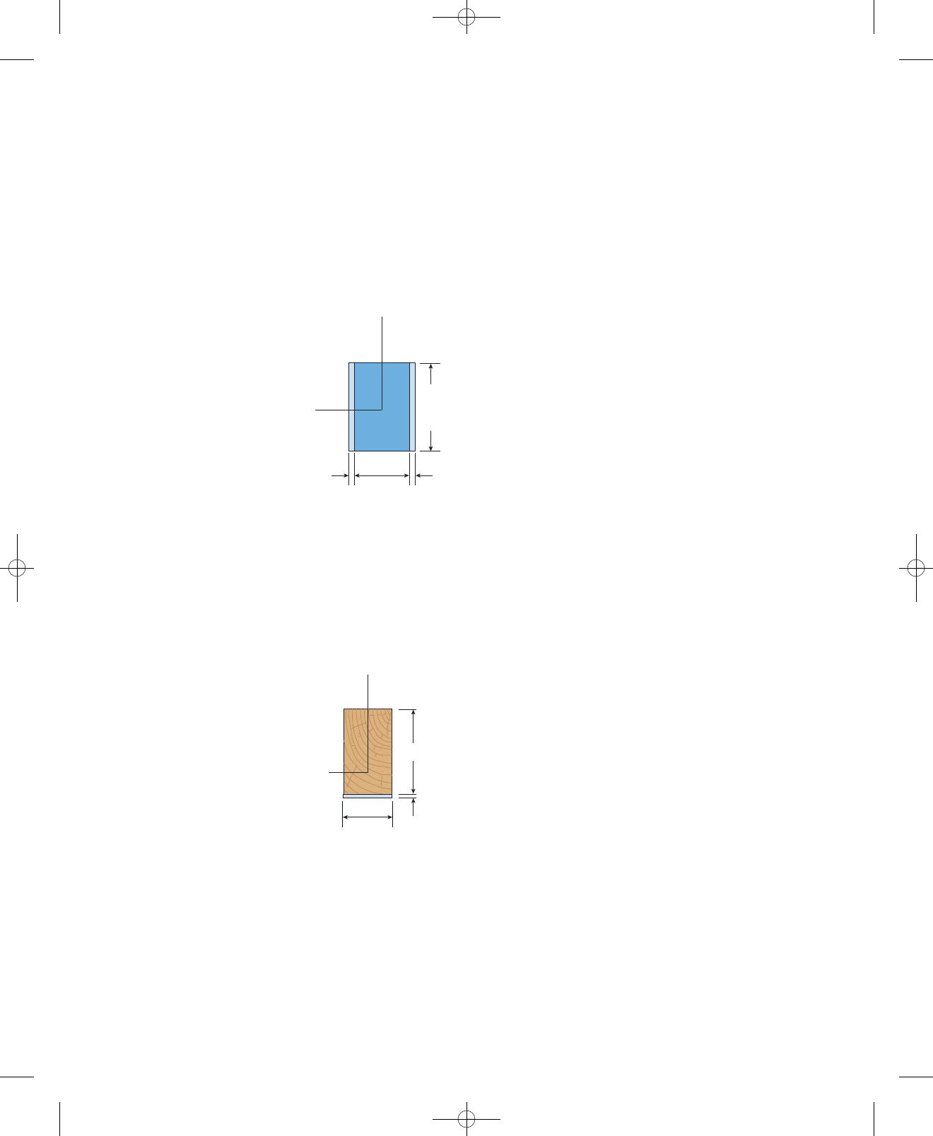
A-6.1: A composite beam is made up of a core
and an exterior cover sheet
on each side. Allowable stresses in core and exterior
sheets are 9.5 MPa and 140 MPa, respectively. The ratio of the maximum
permissible bending moment about the zaxis to that about the yaxis is
most nearly:
(A) 0.5
(B) 0.7
(C) 1.2
(D) 1.5
(300 mm ⫻12 mm,
Ee⫽100 GPa)
(Ec⫽14 GPa)
200 mm ⫻300 mm
A-6.2: A composite beam is made up of a wood beam
and a steel bottom cover plate
. Allowable stresses in wood and steel are 6.5 MPa and
110 MPa, respectively. The allowable bending moment about the zaxis of
the composite beam is most nearly:
(A) 2.9 kN⭈m
(B) 3.5 kN⭈m
(C) 4.3 kN⭈m
(D) 9.9 kN⭈m
(90 mm ⫻8 mm,
90 mm ⫻160 mm
Es⫽190 GPa)
(Ew⫽11 GPa)
A-6.3: A steel pipe has a plastic liner with
inner diameter . The modulus of elasticity of the steel is 75
times that of the modulus of the plastic. Allowable stresses in steel and
plastic are 40 MPa and 550 kPa, respectively. The allowable bending
moment for the composite pipe is approximately:
(A) 1100 N⭈m
(B) 1230 N⭈m
(C) 1370 N⭈m
(D) 1460 N⭈m
d1⫽82 mm
(d3⫽104 mm, d2⫽96 mm)
77735_14_appA_p995-1036.qxd:77735_14_appA_p995-1036.qxd 10/21/11 9:43 AM Page 1017
Appendix A FE Exam Review Problems
1018
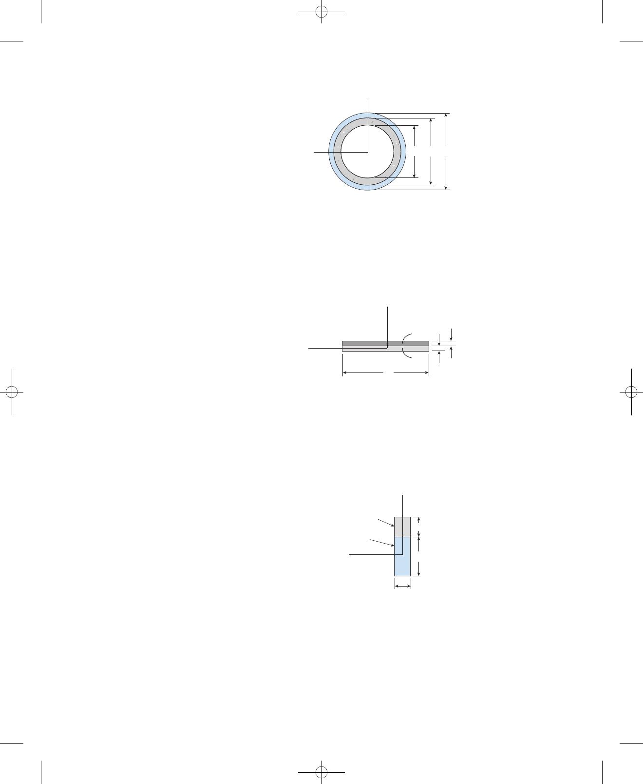
A-6.4: A bimetallic beam of aluminum and copper
strips has a width of ; each strip has a thick-
ness . A bending moment of 1.75 N⭈m is applied about
the zaxis. The ratio of the maximum stress in the aluminum to that in the
copper is approximately:
(A) 0.6
(B) 0.8
(C) 1.0
(D) 1.5
t⫽1.5 mm
(Ec⫽110 GPa) b⫽25 mm
(Ea⫽70 GPa)
z
y
Cd1d2d3
A-6.5: A composite beam of aluminum and steel
has a width and heights and
, respectively. A bending moment is applied about the zaxis
resulting in a maximum stress in the aluminum of 55 MPa. The maximum
stress in the steel is approximately:
(A) 86 MPa
(B) 90 MPa
(C) 94 MPa
(D) 98 MPa
hs⫽68 mm
(Es⫽190 GPa) b⫽25 mm ha⫽42 mm
(Ea⫽72 GPa)
bt
t
z
y
OC
A
ha
b
hs
Aluminum
Steel
z
y
O
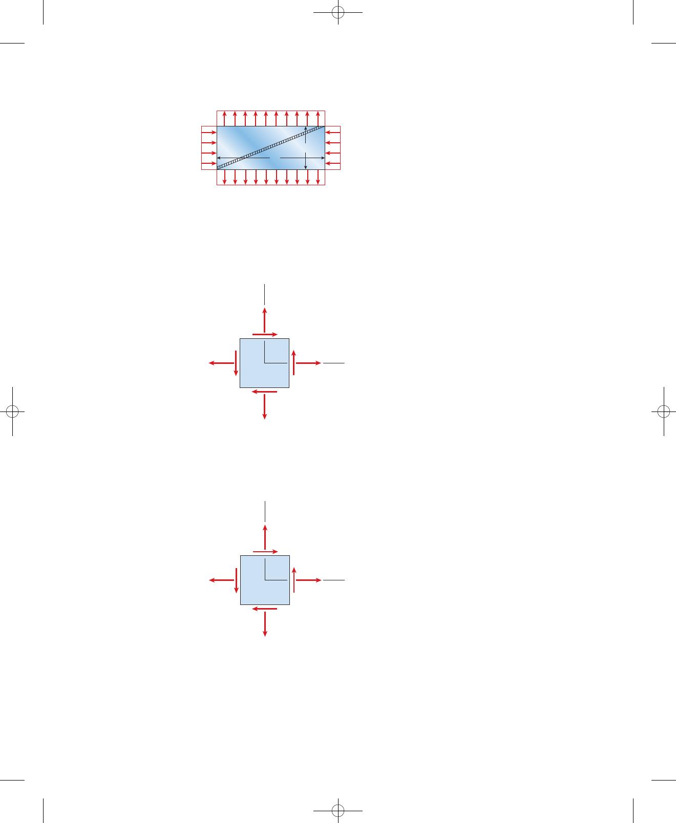
A-7.1: A rectangular plate is subjected to
compressive stress and tensile stress . The
ratio of the normal stress acting perpendicular to the weld to the shear
stress acting along the weld is approximately:
(A) 0.27
(B) 0.54
(C) 0.85
(D) 1.22
σx⫽⫺4.5 MPa σy⫽15 MPa
(a⫽120 mm, b⫽160 mm)
77735_14_appA_p995-1036.qxd:77735_14_appA_p995-1036.qxd 10/21/11 9:43 AM Page 1018
Appendix A FE Exam Review Problems 1019
σy
Weld
σ
x
a
b
y
x
O
τxy
σy
σx
y
x
O
τxy
σy
σx
A-7.2: A rectangular plate in plane stress is subjected to normal stresses σx
and σyand shear stress τxy. Stress σxis known to be 15 MPa, but σyand
τxy are unknown. However, the normal stress is known to be 33 MPa at
counterclockwise angles of 35⬚and 75⬚from the xaxis. Based on this, the
normal stress σyon the element in the figure is approximately:
(A) 14 MPa
(B) 21 MPa
(C) 26 MPa
(D) 43 MPa
A-7.3: A rectangular plate in plane stress is subjected to normal stresses
, , and shear stress . The ratio
of the magnitudes of the principal stresses is approximately:
(A) 0.8
(B) 1.5
(C) 2.1
(D) 2.9
(σ1/σ2)
σx⫽35 MPa σy⫽26 MPa τxy ⫽14 MPa
A-7.4: A drive shaft resists torsional shear stress of 45 MPa and axial com-
pressive stress of 100 MPa. The ratio of the magnitudes of the principal
stresses is approximately:
(A) 0.15
(B) 0.55
(C) 1.2
(D) 1.9
(σ1/σ2)
77735_14_appA_p995-1036.qxd:77735_14_appA_p995-1036.qxd 10/21/11 9:43 AM Page 1019
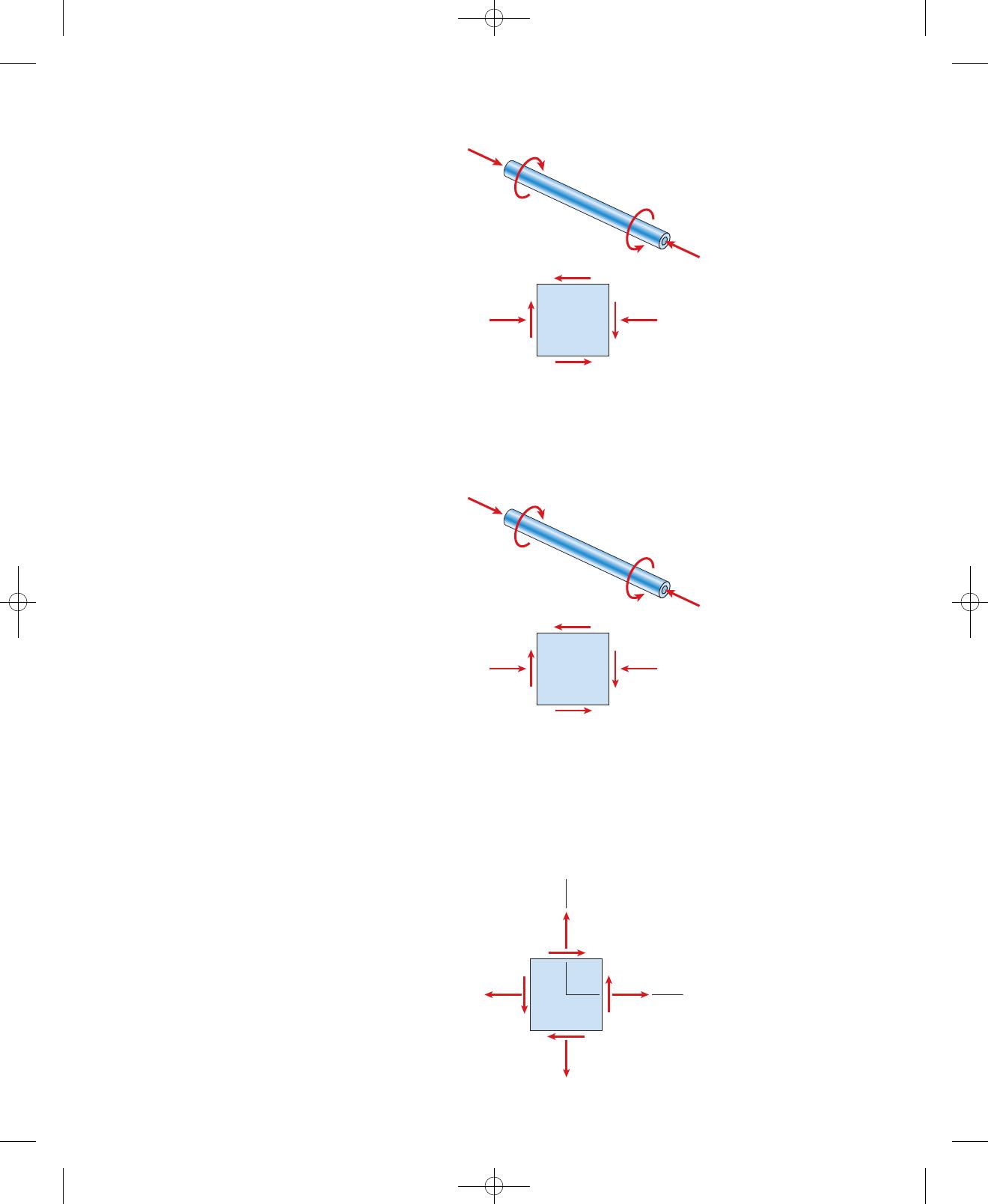
Appendix A FE Exam Review Problems
1020
100 MPa
45 MPa
100 MPa
45 MPa
y
x
O
τxy
σy
σx
A-7.5: A drive shaft resists torsional shear stress of 45 MPa and axial com-
pressive stress of 100 MPa. The maximum shear stress is approximately:
(A) 42 MPa
(B) 67 MPa
(C) 71 MPa
(D) 93 MPa
A-7.6: A drive shaft resists torsional shear stress of and
axial compressive stress . One principal normal stress is
known to be 38 MPa (tensile). The stress σyis approximately:
(A) 23 MPa
(B) 35 MPa
(C) 62 MPa
(D) 75 MPa
σx⫽⫺70 MPa
τxy ⫽40 MPa
77735_14_appA_p995-1036.qxd:77735_14_appA_p995-1036.qxd 10/21/11 9:43 AM Page 1020
Appendix A FE Exam Review Problems 1021
P
c
A
bd
h
h
b
q
a
L
Weld
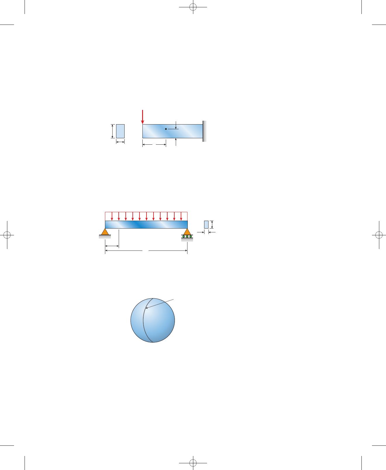
A-7.7: A cantilever beam with rectangular cross section
supports load at its free end. The ratio of the
magnitudes of the principal stresses at point A(at
distance from the free end and distance up from
the bottom) is approximately:
(A) 5
(B) 12
(C) 18
(D) 25
h⫽300 mm)
(b⫽95 mm,
P⫽160 kN
c⫽0.8 m d⫽200 mm
(σ1/σ2)
A-8.1: A thin-walled spherical tank with a diameter of 1.5 m and wall
thickness of 65 mm has an internal pressure of 20 MPa. The maximum
shear stress in the wall of the tank is approximately:
(A) 58 MPa
(B) 67 MPa
(C) 115 MPa
(D) 127 MPa
A-7.8: A simply supported beam with rectangular cross sec-
tion supports uniform load .
The ratio of the magnitudes of the principal stresses at a
point from the left support and distance up from
the bottom of the beam is approximately:
(A) 9
(B) 17
(C) 31
(D) 41
a⫽1.0 m d⫽100 mm
(σ1/σ2)
(b⫽95 mm, h⫽280 mm) q⫽25 kN/m
(L⫽4.5 m)
A-8.2: A thin-walled spherical tank has a diameter of 0.75 m and an inter-
nal pressure of 20 MPa. The yield stress in tension is 920 MPa, the yield
stress in shear is 475 MPa, and the factor of safety is 2.5. The modulus of
elasticity is 210 GPa, Poisson’s ratio is 0.28, and maximum normal strain
is . The minimum permissible thickness of the tank is
approximately:
(A) 8.6 mm
(B) 9.9 mm
(C) 10.5 mm
(D) 11.1 mm
1220 ⫻10⫺6
77735_14_appA_p995-1036.qxd:77735_14_appA_p995-1036.qxd 10/21/11 9:43 AM Page 1021
Appendix A FE Exam Review Problems
1022
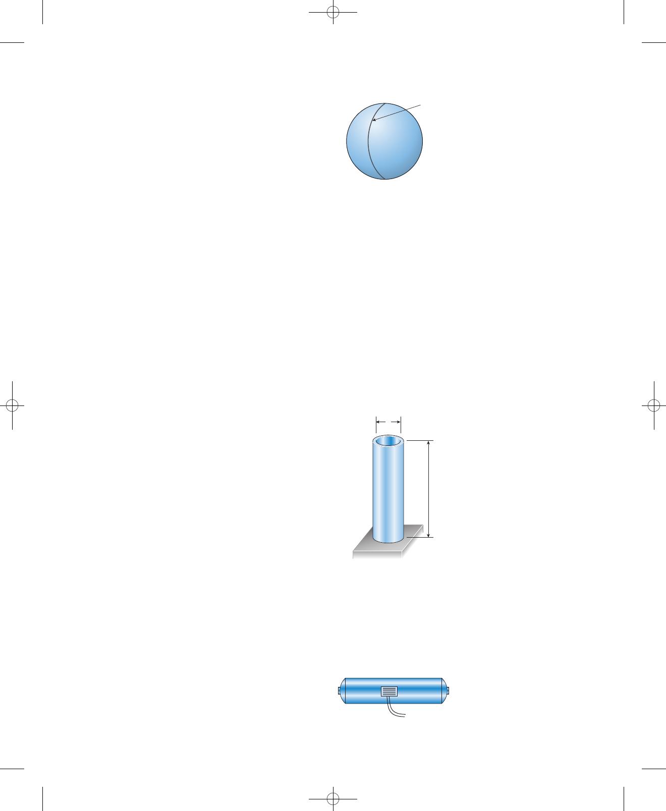
A-8.3: A thin-walled cylindrical tank with a diameter of 200 mm has an
internal pressure of 11 MPa. The yield stress in tension is 250 MPa, the
yield stress in shear is 140 MPa, and the factor of safety is 2.5. The mini-
mum permissible thickness of the tank is approximately:
(A) 8.2 mm
(B) 9.1 mm
(C) 9.8 mm
(D) 11.0 mm
A-8.4: A thin-walled cylindrical tank with a diameter of 2.0 m and wall
thickness of 18 mm is open at the top. The height hof water
in the tank at which the circumferential
stress reaches 10 MPa in the tank wall is approximately:
(A) 14 m
(B) 18 m
(C) 20 m
(D) 24 m
(weight density ⫽9.81 kN/m3)
d
h
Strain
g
a
g
e
A-8.5: The pressure relief valve is opened on a thin-walled cylindrical tank,
with the radius-to-wall thickness ratio of 128, thereby decreasing the lon-
gitudinal strain by . Assume and . The
original internal pressure in the tank was approximately:
(A) 370 kPa
(B) 450 kPa
(C) 500 kPa
(D) 590 kPa
150 ⫻10⫺6E⫽73 GPa ν⫽0.33
Weld
77735_14_appA_p995-1036.qxd:77735_14_appA_p995-1036.qxd 10/21/11 9:43 AM Page 1022
Appendix A FE Exam Review Problems 1023
Welded seams
Welded seams
Welded seams
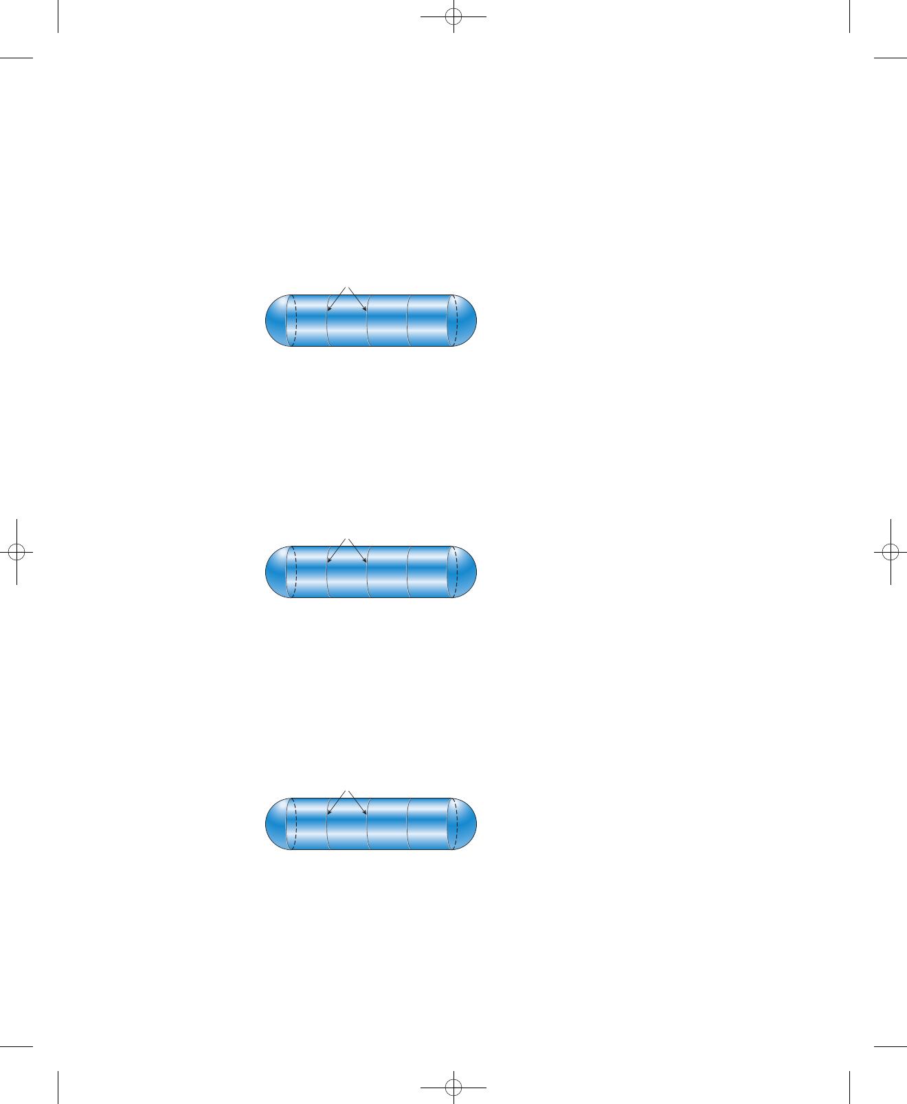
A-8.6: A cylindrical tank is assembled by welding steel sections circumfer-
entially. Tank diameter is 1.5 m, thickness is 20 mm, and internal pressure
is 2.0 MPa. The maximum stress in the heads of the tank is approximately:
(A) 38 MPa
(B) 45 MPa
(C) 50 MPa
(D) 59 MPa
A-8.7: A cylindrical tank is assembled by welding steel sections circumfer-
entially. Tank diameter is 1.5 m, thickness is 20 mm, and internal pressure
is 2.0 MPa. The maximum tensile stress in the cylindrical part of the tank
is approximately:
(A) 45 MPa
(B) 57 MPa
(C) 62 MPa
(D) 75 MPa
A-8.8: A cylindrical tank is assembled by welding steel sections circumfer-
entially. Tank diameter is 1.5 m, thickness is 20 mm, and internal pressure
is 2.0 MPa. The maximum tensile stress perpendicular to the welds is
approximately:
(A) 22 MPa
(B) 29 MPa
(C) 33 MPa
(D) 37 MPa
A-8.9: A cylindrical tank is assembled by welding steel sections circumfer-
entially. Tank diameter is 1.5 m, thickness is 20 mm, and internal pressure
is 2.0 MPa. The maximum shear stress in the heads is approximately:
(A) 19 MPa
(B) 23 MPa
(C) 33 MPa
(D) 35 MPa
77735_14_appA_p995-1036.qxd:77735_14_appA_p995-1036.qxd 10/21/11 9:43 AM Page 1023
Appendix A FE Exam Review Problems
1024
A-8.10: A cylindrical tank is assembled by welding steel sections circum-
ferentially. Tank diameter is 1.5 m, thickness is 20 mm, and internal pres-
sure is 2.0 MPa. The maximum shear stress in the cylindrical part of the
tank is approximately:
(A) 17 MPa
(B) 26 MPa
(C) 34 MPa
(D) 38 MPa
Welded seams
Welded seams
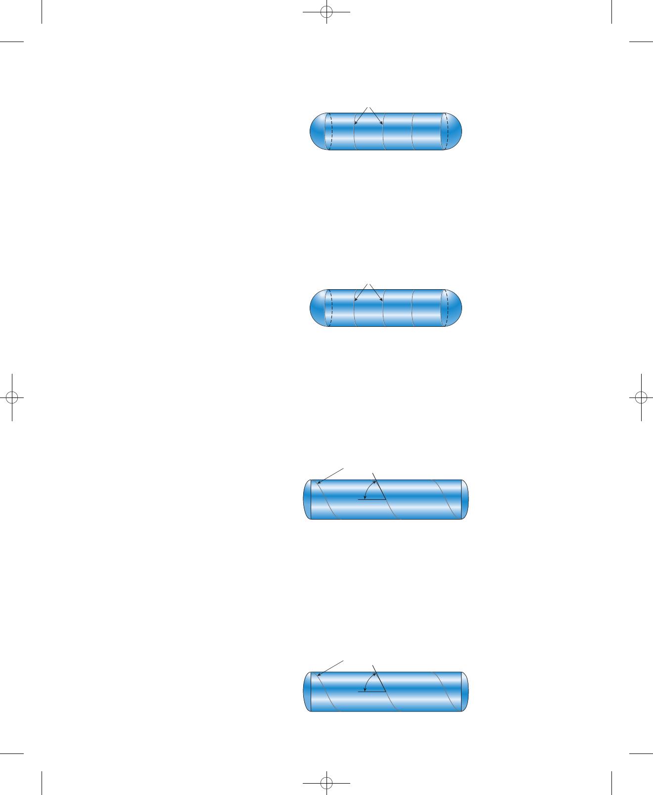
A-8.11: A cylindrical tank is assembled by welding steel sections in a heli-
cal pattern with angle . Tank diameter is 1.6 m, thickness is
20 mm, and internal pressure is 2.75 MPa. Modulus and
Poisson’s ratio . The circumferential strain in the wall of the
tank is approximately:
(A)
(B)
(C)
(D) 4.5 ⫻10⫺4
3.9 ⫻10⫺4
3.2 ⫻10⫺4
1.9 ⫻10⫺4
ν⫽0.28
E⫽210 GPa
α⫽50°
Helical weld
α
Helical weld
α
A-8.12: A cylindrical tank is assembled by welding steel sections in a heli-
cal pattern with angle . Tank diameter is 1.6 m, thickness is
20 mm, and internal pressure is 2.75 MPa. Modulus and
Poisson’s ratio . The longitudinal strain in the the wall of the
tank is approximately:
(A)
(B)
(C)
(D) 4.3 ⫻10⫺4
3.1 ⫻10⫺4
2.4 ⫻10⫺4
1.2 ⫻10⫺4
ν⫽0.28
E⫽210 GPa
α⫽50°
77735_14_appA_p995-1036.qxd:77735_14_appA_p995-1036.qxd 10/21/11 9:43 AM Page 1024
Appendix A FE Exam Review Problems 1025
Helical weld
α
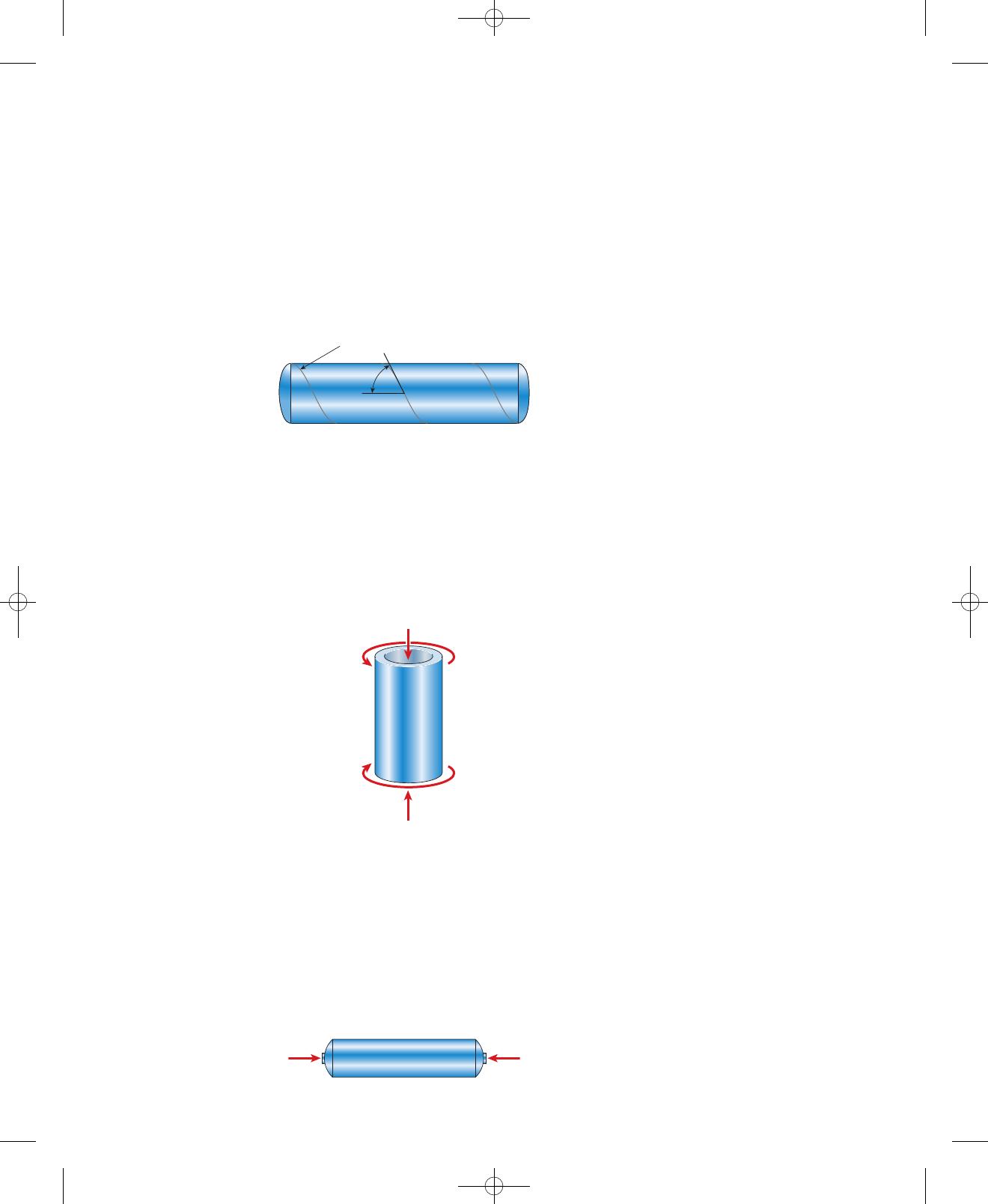
A-8.13: A cylindrical tank is assembled by welding steel sections in a heli-
cal pattern with angle . Tank diameter is 1.6 m, thickness is
20 mm, and internal pressure is 2.75 MPa. Modulus and
Poisson’s ratio . The normal stress acting perpendicular to the
weld is approximately:
(A) 39 MPa
(B) 48 MPa
(C) 78 MPa
(D) 84 MPa
ν⫽0.28
E⫽210 GPa
α⫽50°
P
T
T
P
A-8.14: A segment of a drive shaft is sub-
jected to a torque . The allowable shear stress in the shaft
is 45 MPa. The maximum permissible compressive load Pis approxi-
mately:
(A) 200 kN
(B) 286 kN
(C) 328 kN
(D) 442 kN
T⫽30 kN #m
(d2⫽200 mm, d1⫽160 mm)
A-8.15: A thin-walled cylindrical tank, under internal pressure p, is com-
pressed by a force . Cylinder diameter is and wall
thickness . Allowable normal stress is 110 MPa and allowable
shear stress is 60 MPa. The maximum allowable internal pressure pmax is
approximately:
(A) 5 MPa
(B) 10 MPa
(C) 13 MPa
(D) 17 MPa
t⫽5.5 mm
F⫽75 kN d⫽90 mm
FF
77735_14_appA_p995-1036.qxd:77735_14_appA_p995-1036.qxd 10/21/11 9:43 AM Page 1025
Appendix A FE Exam Review Problems
1026
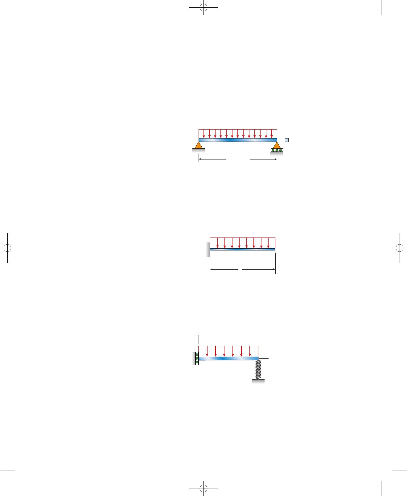
A-9.1: An aluminum beam with a square cross section and
span length is subjected to uniform load . The
allowable bending stress is 60 MPa. The maximum deflection of the beam
is approximately:
(A) 10 mm
(B) 16 mm
(C) 22 mm
(D) 26 mm
L⫽2.5 m q⫽1.5 kN/m
(E⫽72 GPa)
q = 1.5 kN/m
L = 2.5 m
A-9.2: An aluminum cantilever beam with a square cross sec-
tion and span length is subjected to uniform load
The allowable bending stress is 55 MPa. The maximum deflection of the
beam is approximately:
(A) 10 mm
(B) 20 mm
(C) 30 mm
(D) 40 mm
q⫽1.5 kN/m.L⫽2.5 m
(E⫽72 GPa)
L
q
k = 48EI/L3
AB
q
y
x
L
A-9.3: A steel beam with and span
length is subjected to uniform load . The maxi-
mum deflection of the beam is approximately:
(A) 10 mm
(B) 13 mm
(C) 17 mm
(D) 19 mm
L⫽3.5 m q⫽9.5 kN/m
(E⫽210 GPa) I⫽119 ⫻106mm4
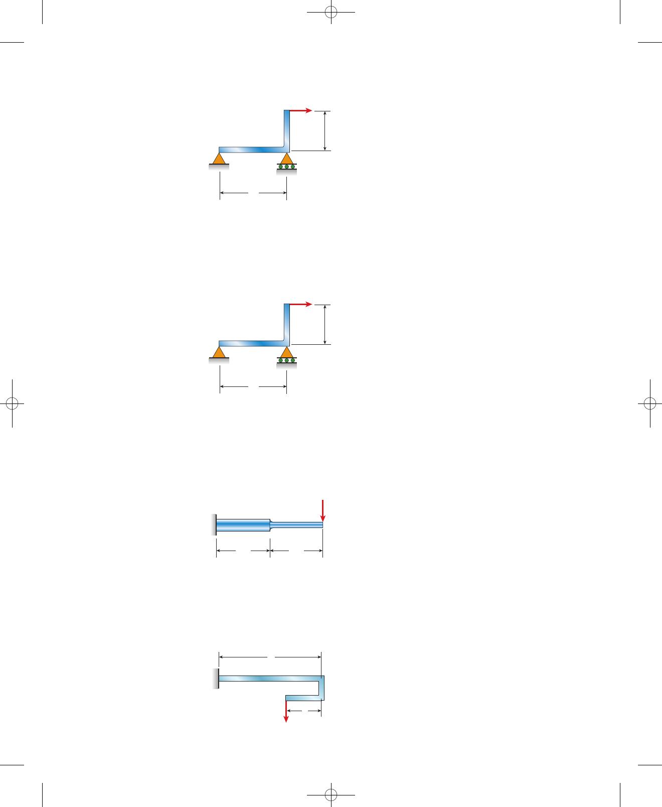
A-9.4: A steel bracket ABC with span length
and height is subjected to load at C.
The maximum rotation of joint Bis approximately:
(A) 0.1⬚
(B) 0.3⬚
(C) 0.6⬚
(D) 0.9⬚
L⫽4.5 m H⫽2m P⫽15 kN
(EI ⫽4.2 ⫻106N#m2)
77735_14_appA_p995-1036.qxd:77735_14_appA_p995-1036.qxd 10/21/11 9:43 AM Page 1026
Appendix A FE Exam Review Problems 1027
A
C
B
H
P
L
A
C
B
H
P
L
L
AB
C
D
P
a
A-9.5: A steel bracket ABC with span
length and height is subjected to load
at C. The maximum horizontal displacement of joint Cis approximately:
(A) 22 mm
(B) 31 mm
(C) 38 mm
(D) 40 mm
L⫽4.5 m H⫽2m P⫽15 kN
(EI ⫽4.2 ⫻106N#m2)
A-9.6: A nonprismatic cantilever beam of one material is subjected to
load Pat its free end. Moment of inertia . The ratio rof the
deflection to the deflection at the free end of a prismatic cantilever
with moment of inertia I1carrying the same load is approximately:
(A) 0.25
(B) 0.40
(C) 0.56
(D) 0.78
δBδ1
I2⫽2I1
B
C
AI1
I2
P
L
2
—L
2
—
A-9.7: A steel bracket ABCD , with span length
and dimension , is subjected to load at D.
The maximum deflection at Bis approximately:
(A) 10 mm
(B) 14 mm
(C) 19 mm
(D) 24 mm
L⫽4.5 m a⫽2m P⫽10 kN
(EI ⫽4.2 ⫻106N#m2)
77735_14_appA_p995-1036.qxd:77735_14_appA_p995-1036.qxd 10/21/11 9:44 AM Page 1027
Appendix A FE Exam Review Problems
1028
A
x
B
L
M1
MA1
y
A
x
B
L
M2C
L/2
MA2
y
AB
L
M1
θB1
x
y
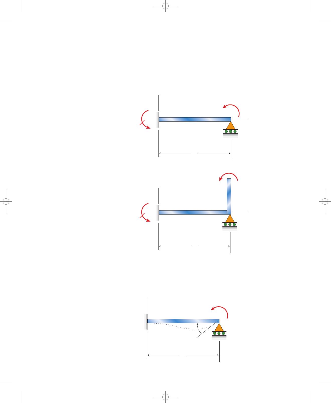
A-10.1: Propped cantilever beam AB has moment M1applied at joint B.
Framework ABC has moment M2applied at C. Both structures have con-
stant flexural rigidity EI. If the ratio of the applied moments ,
the ratio of the reactive moments at clamped support Ais
approximately:
(A) 1
(B) 3/2
(C) 2
(D) 5/2
M1/M2⫽3/2
MA1/MA2
A-10.2: Propped cantilever beam AB has moment M1applied at joint B.
Framework ABC has moment M2applied at C. Both structures have con-
stant flexural rigidity EI. If the ratio of the applied moments ,
the ratio of the joint rotations at B, , is approximately:
(A) 1
(B) 3/2
(C) 2
(D) 5/2
M1/M2⫽3/2
θB1/θB2
77735_14_appA_p995-1036.qxd:77735_14_appA_p995-1036.qxd 10/21/11 9:44 AM Page 1028
Appendix A FE Exam Review Problems 1029
θB2
A
x
B
L
M2C
L/2
y
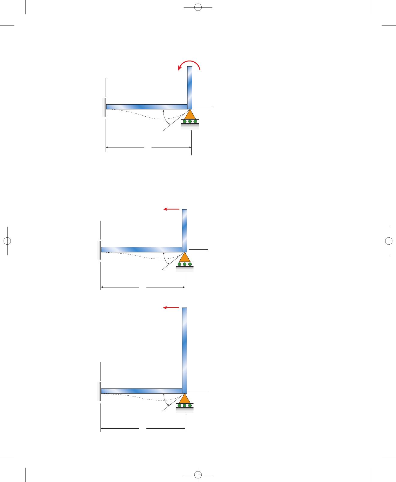
A-10.3: Structure 1 with member BC of length L/2 has force P1applied at
joint C. Structure 2 with member BC of length Lhas force P2applied at C.
Both structures have constant flexural rigidity EI. If the ratio of the
applied forces , the ratio of the joint B rotations is
approximately:
(A) 1
(B) 5/4
(C) 3/2
(D) 2
P1/P2⫽5/2 θB1/θB2
A
x
B
C
C
L
L/2
P1
y
A
x
B
y
P2
L
L
θB1
θB1
77735_14_appA_p995-1036.qxd:77735_14_appA_p995-1036.qxd 10/21/11 9:44 AM Page 1029
Appendix A FE Exam Review Problems
1030
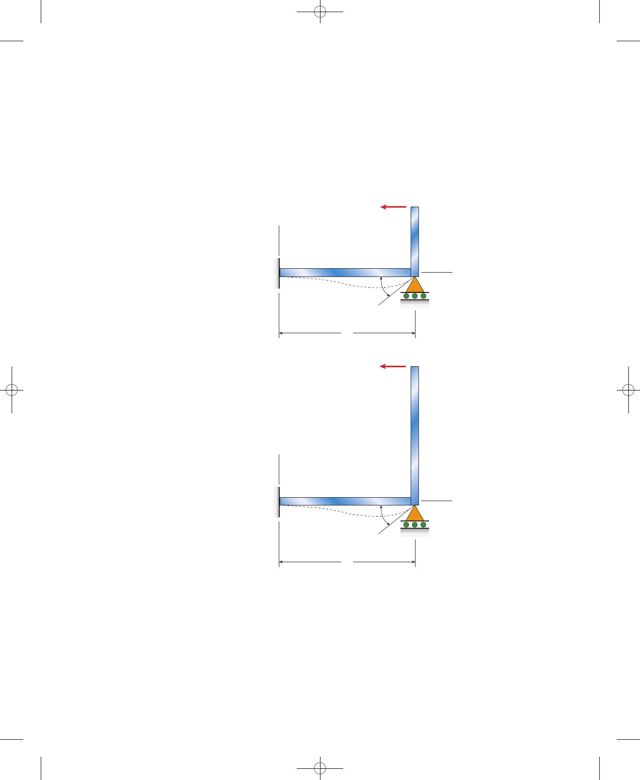
A-10.4: Structure 1 with member BC of length L/2 has force P1applied at
joint C. Structure 2 with member BC of length Lhas force P2applied at C.
Both structures have constant flexural rigidity EI. The required ratio of
the applied forces so that joint B rotations θB1and θB2are equal is
approximately:
(A) 1
(B) 5/4
(C) 3/2
(D) 2
P1/P2
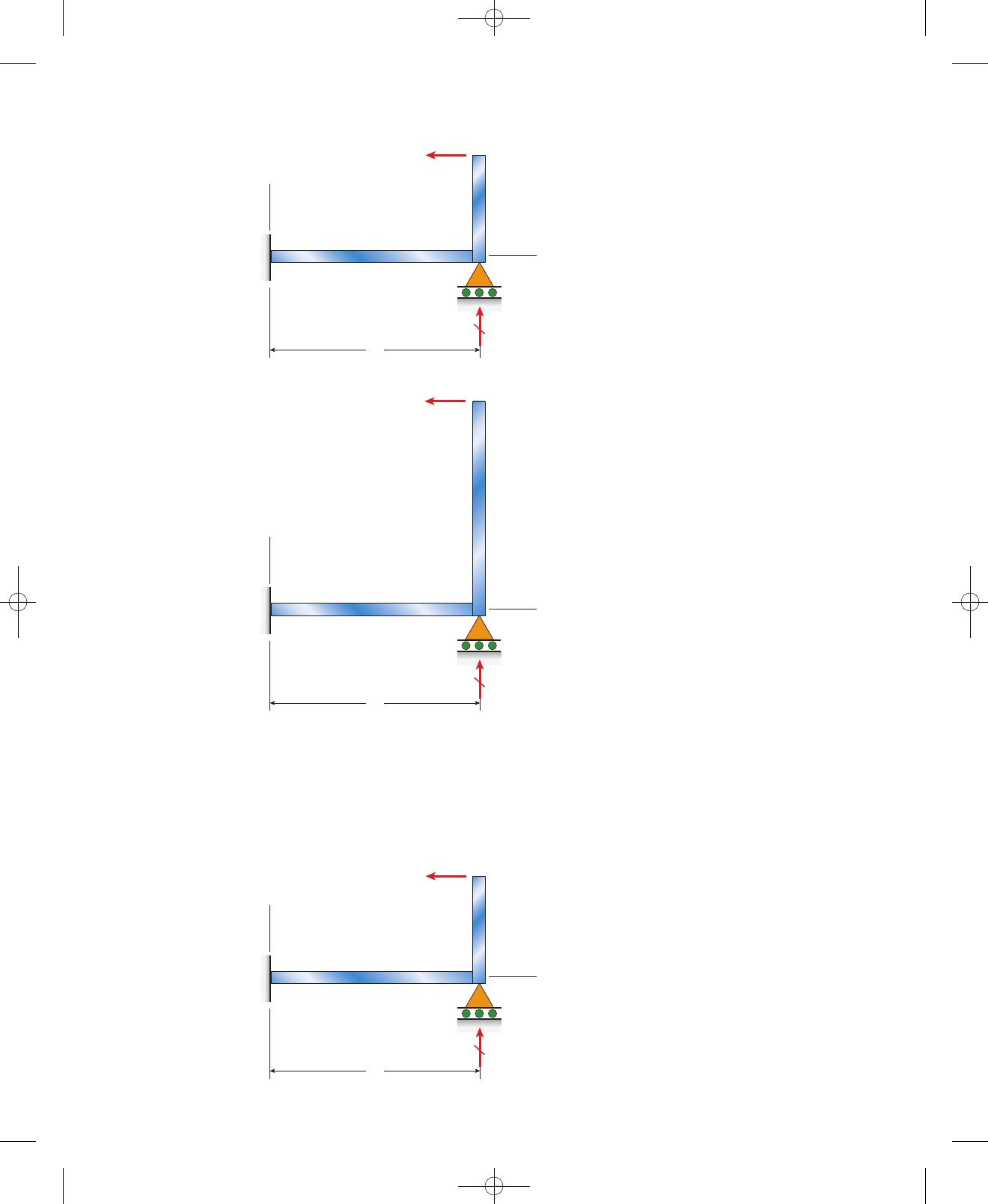
A-10.5: Structure 1 with member BC of length L/2 has force P1applied at
joint C. Structure 2 with member BC of length Lhas force P2applied at C.
Both structures have constant flexural rigidity EI. If the ratio of the
applied forces , the ratio of the joint B reactions is
approximately:
(A) 1
(B) 5/4
(C) 3/2
(D) 2
P1/P2⫽5/2 RB1/RB2
A
x
B
C
C
L
L/2
P1
y
A
x
B
y
P2
L
L
θB1
θB2
77735_14_appA_p995-1036.qxd:77735_14_appA_p995-1036.qxd 10/21/11 9:44 AM Page 1030
Appendix A FE Exam Review Problems 1031
A
x
B
RB1
C
C
L
L/2
P1
y
A
x
B
y
P2
RB2
L
L
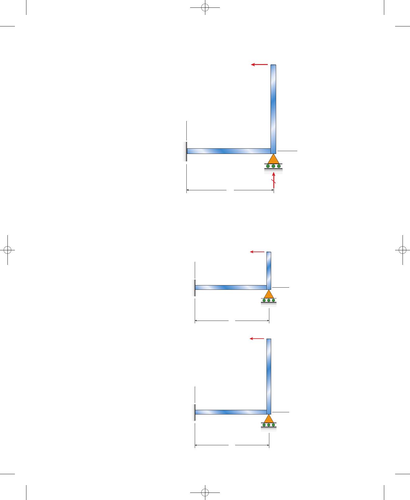
A-10.6: Structure 1 with member BC of length L/2 has force P1applied at
joint C. Structure 2 with member BC of length Lhas force P2applied at C.
Both structures have constant flexural rigidity EI. The required ratio of
the applied forces so that joint B reactions RB1and RB2are equal is
approximately:
(A) 1
(B) 5/4
(C) 3/2
(D) 2
P1/P2
A
x
B
RB1
C
L
L/2
P1
y
77735_14_appA_p995-1036.qxd:77735_14_appA_p995-1036.qxd 10/21/11 9:44 AM Page 1031
Appendix A FE Exam Review Problems
1032
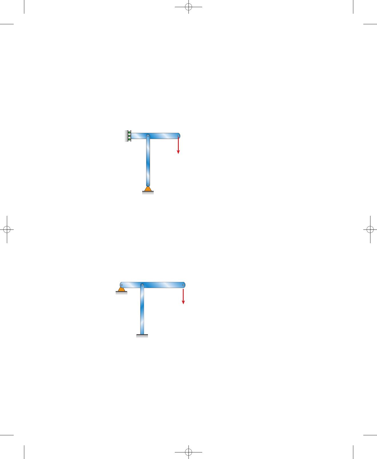
A-10.7: Structure 1 with member BC of length L/2 has force P1applied at
joint C. Structure 2 with member BC of length Lhas force P2applied at C.
Both structures have constant flexural rigidity EI. If the ratio of the
applied forces , the ratio of the joint C lateral deflections
is approximately:
(A) 1/2
(B) 4/5
(C) 3/2
(D) 2
δC1/δC2
P1/P2⫽5/2
A
x
B
δC1
δC2
C
C
L
L/2
P1
y
A
x
B
y
P2
L
L
C
A
x
B
y
P2
RB2
L
L
77735_14_appA_p995-1036.qxd:77735_14_appA_p995-1036.qxd 10/21/11 9:44 AM Page 1032
Appendix A FE Exam Review Problems 1033
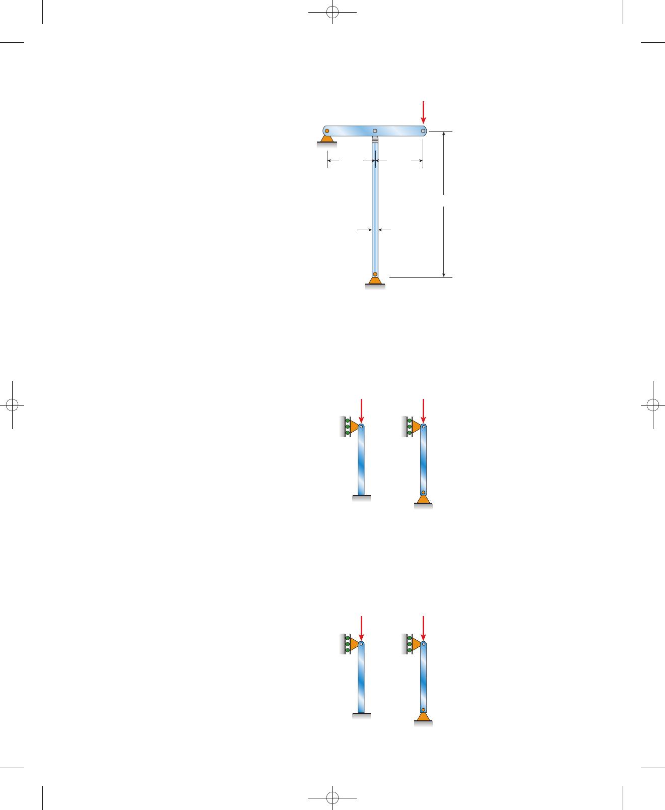
A-11.1: Beam ACB has a sliding support at Aand is supported at Cby a
pinned-end steel column with square cross section
and height . The column must resist a load Qat
Bwith a factor of safety of 2.0 with respect to the critical load. The max-
imum permissible value of Qis approximately:
(A) 10.5 kN
(B) 11.8 kN
(C) 13.2 kN
(D) 15.0 kN
(E⫽200 GPa,
b⫽40 mm) L⫽3.75 m
B
D
AC
L
Q
d2d
B
D
AC
LQ
d2d
A-11.2: Beam ACB has a pin support at Aand is supported at Cby a steel
column with a square cross section and
height . The column is pinned at Cand fixed at D. The column
must resist a load Qat Bwith a factor of safety of 2.0 with respect to the
critical load. The maximum permissible value of Qis approximately:
(A) 3.0 kN
(B) 6.0 kN
(C) 9.4 kN
(D) 10.1 kN
L⫽5.25 m
(E⫽190 GPa, b⫽42 mm)
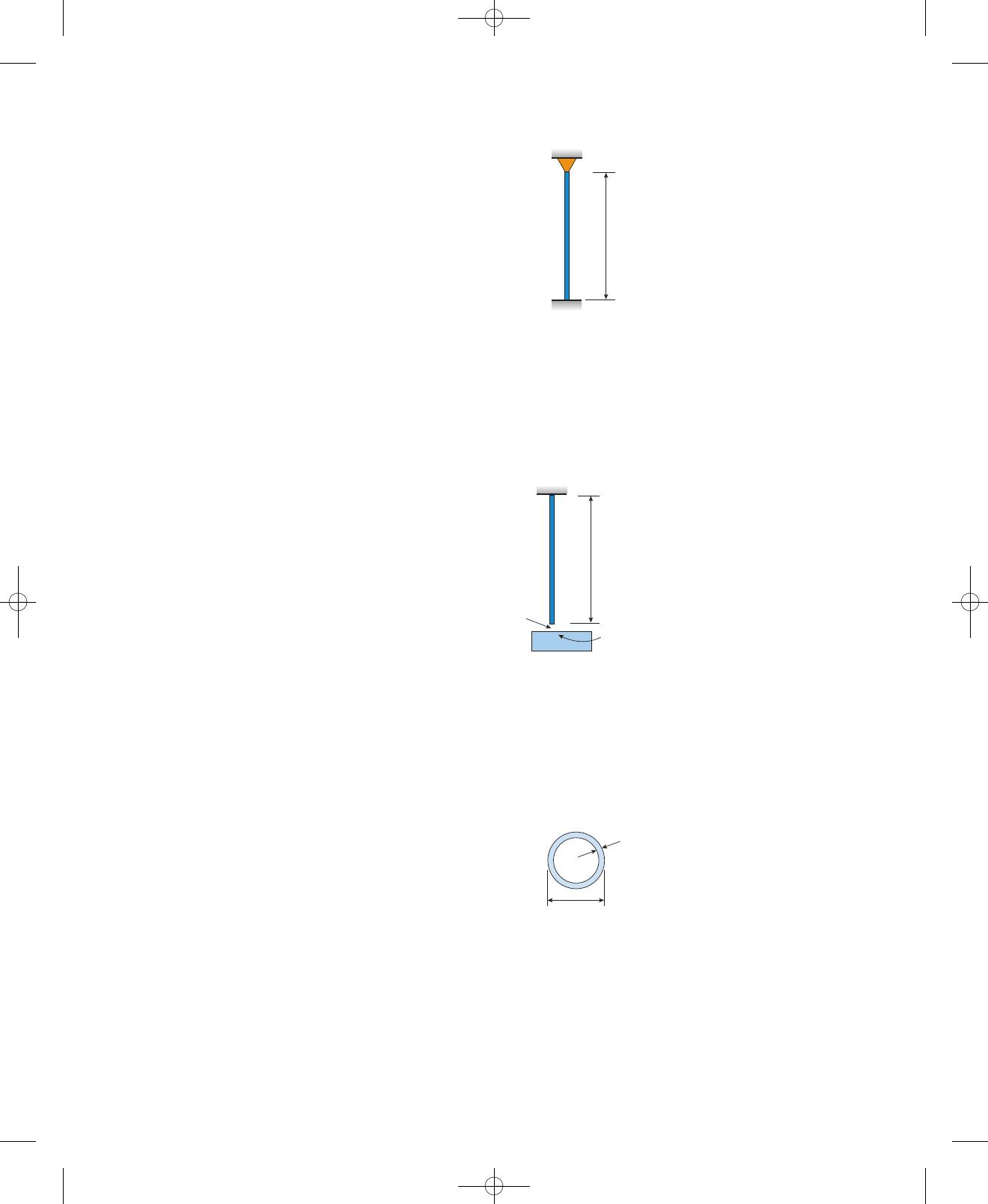
A-11.3: A steel pipe column
of length is subjected to a
temperature increase ⌬T. The column is pinned at the top and fixed at the
bottom. The temperature increase at which the column will buckle is
approximately:
(A) 36 ⬚C
(B) 42 ⬚C
(C) 54 ⬚C
(D) 58 ⬚C
(E⫽190 GPa, α⫽14 ⫻10⫺6/°C,
d2⫽82 mm, and d1⫽70 mm) L⫽4.25 m
77735_14_appA_p995-1036.qxd:77735_14_appA_p995-1036.qxd 10/21/11 9:44 AM Page 1033
Appendix A FE Exam Review Problems
1034
A-11.4: A steel pipe
of length hangs from a rigid surface and is
subjected to a temperature increase . The column is fixed at
the top and has a small gap at the bottom. To avoid buckling, the mini-
mum clearance at the bottom should be approximately:
(A) 2.55 mm
(B) 3.24 mm
(C) 4.17 mm
(D) 5.23 mm
(E⫽190 GPa, α⫽14 ⫻10⫺6/°C, d2⫽82 mm,
¢T⫽50 °C
L⫽4.25 mand d1⫽70 mm)
A-11.5: A pinned-end copper strut with
length is constructed of circular tubing with outside
diameter . The strut must resist an axial load with
a factor of safety of 2.0 with respect to the critical load. The required
thickness tof the tube is approximately:
(A) 2.75 mm
(B) 3.15 mm
(C) 3.89 mm
(D) 4.33 mm
d⫽38 mm P⫽14 kN
L⫽1.6 m
(E⫽110 GPa)
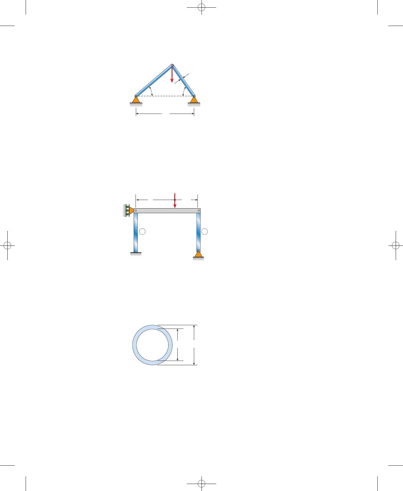
A-11.6: A plane truss composed of two steel pipes
is subjected to vertical
load Wat joint B. Joints Aand Care apart. The critical value of
load Wfor buckling in the plane of the truss is nearly:
(A) 138 kN
(B) 146 kN
(C) 153 kN
(D) 164 kN
(E⫽210 GPa,
L⫽7m
d⫽100 mm, and wall thickness ⫽6.5 mm)
B
L
A
ΔT
L
ΔT
Gap
Frictionless
surface
d
t
77735_14_appA_p995-1036.qxd:77735_14_appA_p995-1036.qxd 10/21/11 9:44 AM Page 1034
Appendix A FE Exam Review Problems 1035
W
A
B
C
40° 50°
L
d
a L-a
Qcr
1
EI
h
EI
h2
A-11.7: A beam is pin-connected to the tops of two identical pipe columns,
each of height h, in a frame. The frame is restrained against sidesway at
the top of column 1. Only buckling of columns 1 and 2 in the plane of the
frame is of interest here. The ratio (a/L) defining the placement of
load Qcr, which causes both columns to buckle simultaneously, is approx-
imately:
(A) 0.25
(B) 0.33
(C) 0.67
(D) 0.75
A-11.8: A steel pipe column with length is
constructed of circular tubing with outside diameter and
inner diameter . The pipe column is fixed at the base and
pinned at the top and may buckle in any direction. The Euler buckling
load of the column is most nearly:
(A) 303 kN
(B) 560 kN
(C) 690 kN
(D) 720 kN
(E⫽210 GPa) L⫽4.25 m
d1⫽64 mm
d2⫽90 mm
d1d2
A-11.9: An aluminum tube AB of circular cross section has
a pinned support at the base and is pin-connected at the top to a horizon-
tal beam supporting a load . The outside diameter of the
tube is 200 mm and the desired factor of safety with respect to Euler buck-
ling is 3.0. The required thickness tof the tube is most nearly:
(A) 8 mm
(B) 10 mm
(C) 12 mm
(D) 14 mm
Q⫽600 kN
(E⫽72 GPa)
77735_14_appA_p995-1036.qxd:77735_14_appA_p995-1036.qxd 10/21/11 9:44 AM Page 1035
Appendix A FE Exam Review Problems
1036
A-11.10: Two pipe columns are required to have the same Euler buckling
load Pcr. Column 1 has flexural rigidity EI and height L1; column 2 has
flexural rigidity (4/3)EI and height L2. The ratio at which both
columns will buckle under the same load is approximately:
(A) 0.55
(B) 0.72
(C) 0.81
(D) 1.10
(L2/L1)
A-11.11: Two pipe columns are required to have the same Euler buckling
load Pcr. Column 1 has flexural rigidity EI1and height L; column 2 has
flexural rigidity (2/3)EI2and height L. The ratio at which both
columns will buckle under the same load is approximately:
(A) 0.8
(B) 1.0
(C) 2.2
(D) 3.1
(I2/I1)
BC
A
d ⫽ 200 mm
Q = 600 kN
1.5 m 1.0 m
2.5 m
EI
Pcr
L1
E
I
L2
Pcr
4
—
3
Pcr
LL
Pcr
EI1EI2
2
—
3
77735_14_appA_p995-1036.qxd:77735_14_appA_p995-1036.qxd 10/21/11 9:44 AM Page 1036
Gere/Goodno:MechanicsofMaterials,9e
FEExamReviewProblems–ANSWERS