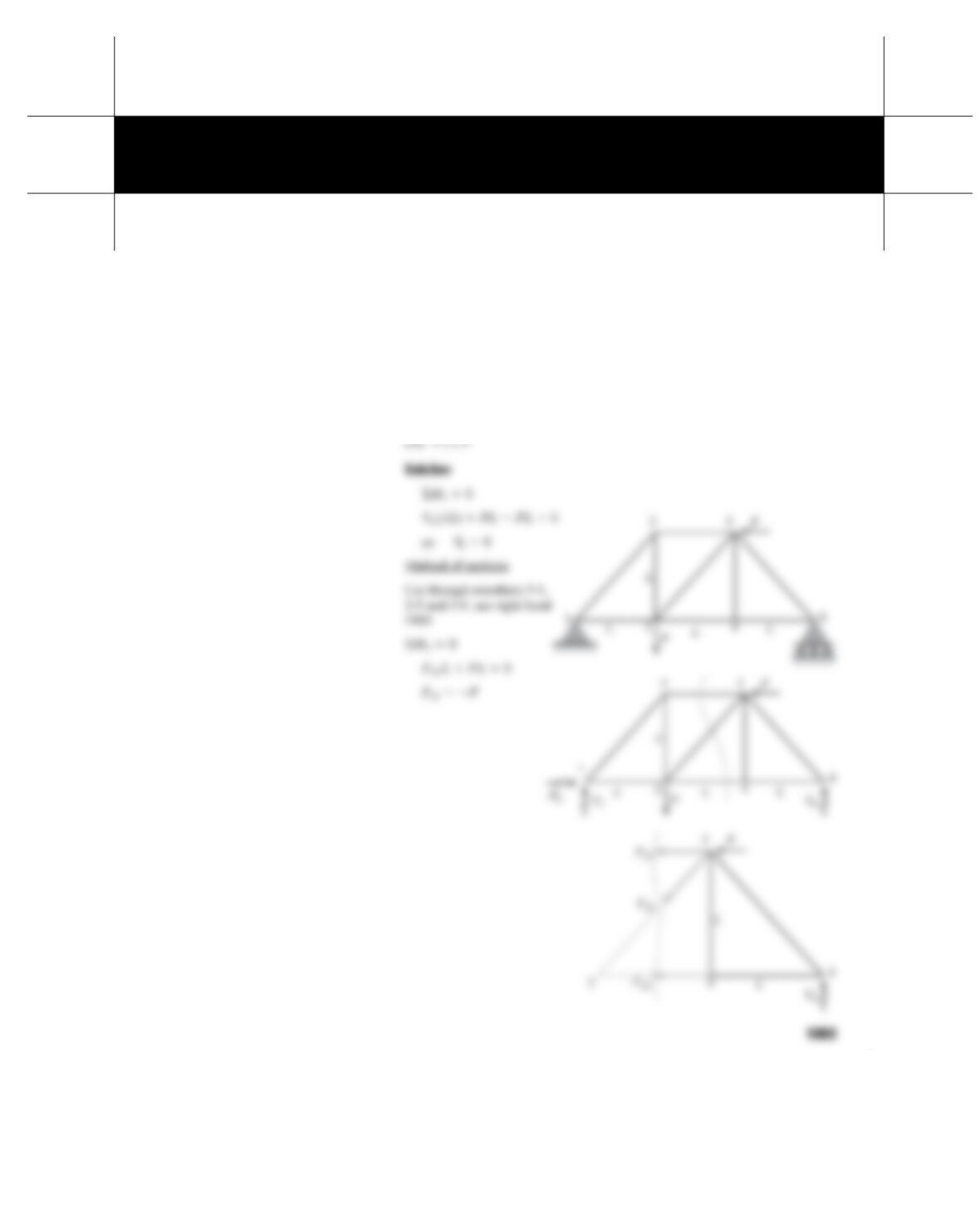
A-1.1: A plane truss has downward applied load Pat joint 2 and another load P
applied leftward at joint 5. The force in member 3–5 is:
(A) 0
(B)
(C)
(D) 1.5 P
P
P/2
Appendix A
Solution
1083
FE Exam Review Problems
78572_app_ptg01_hr_1083-1168.qxd 1/24/12 12:15 PM Page 1083
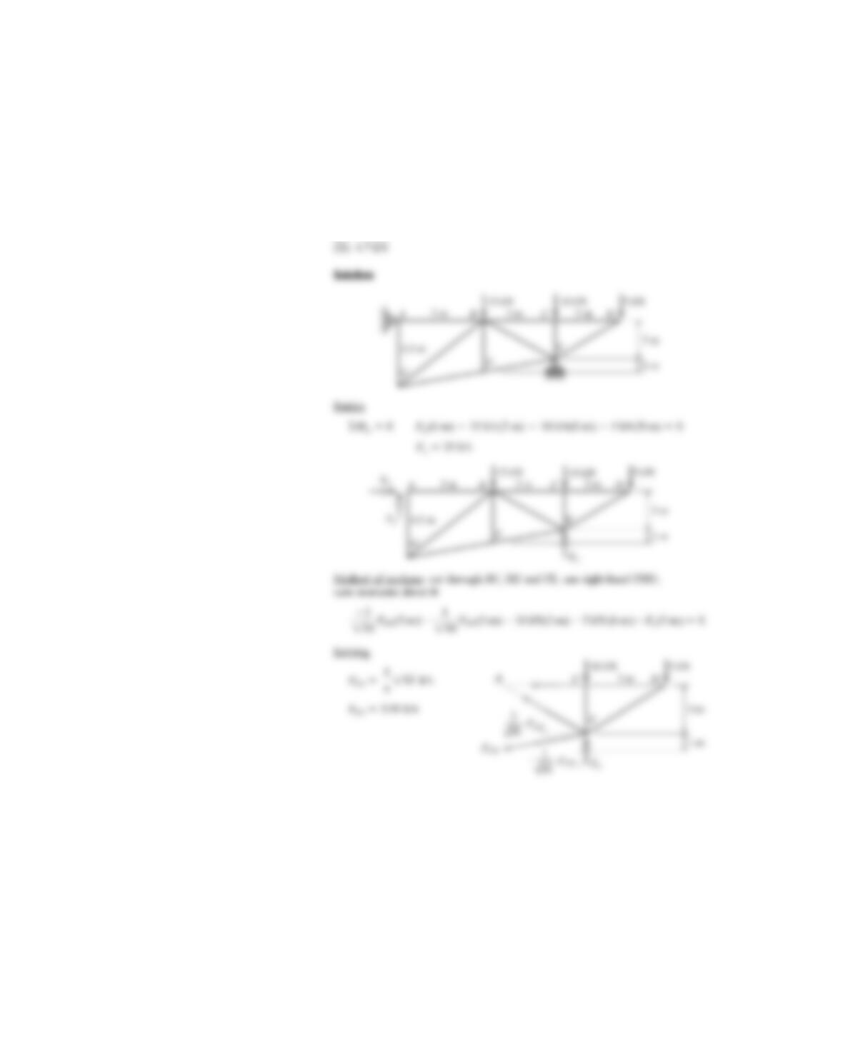
A-1.2: The force in member FE of the plane truss below is approximately:
(A)
(B)
(C) 3.9 kN
(D) 4.7 kN
Solution
2.2 kN
1.5 kN
1084 APPENDIX A FE Exam Review Problems
78572_app_ptg01_hr_1083-1168.qxd 1/24/12 12:15 PM Page 1084
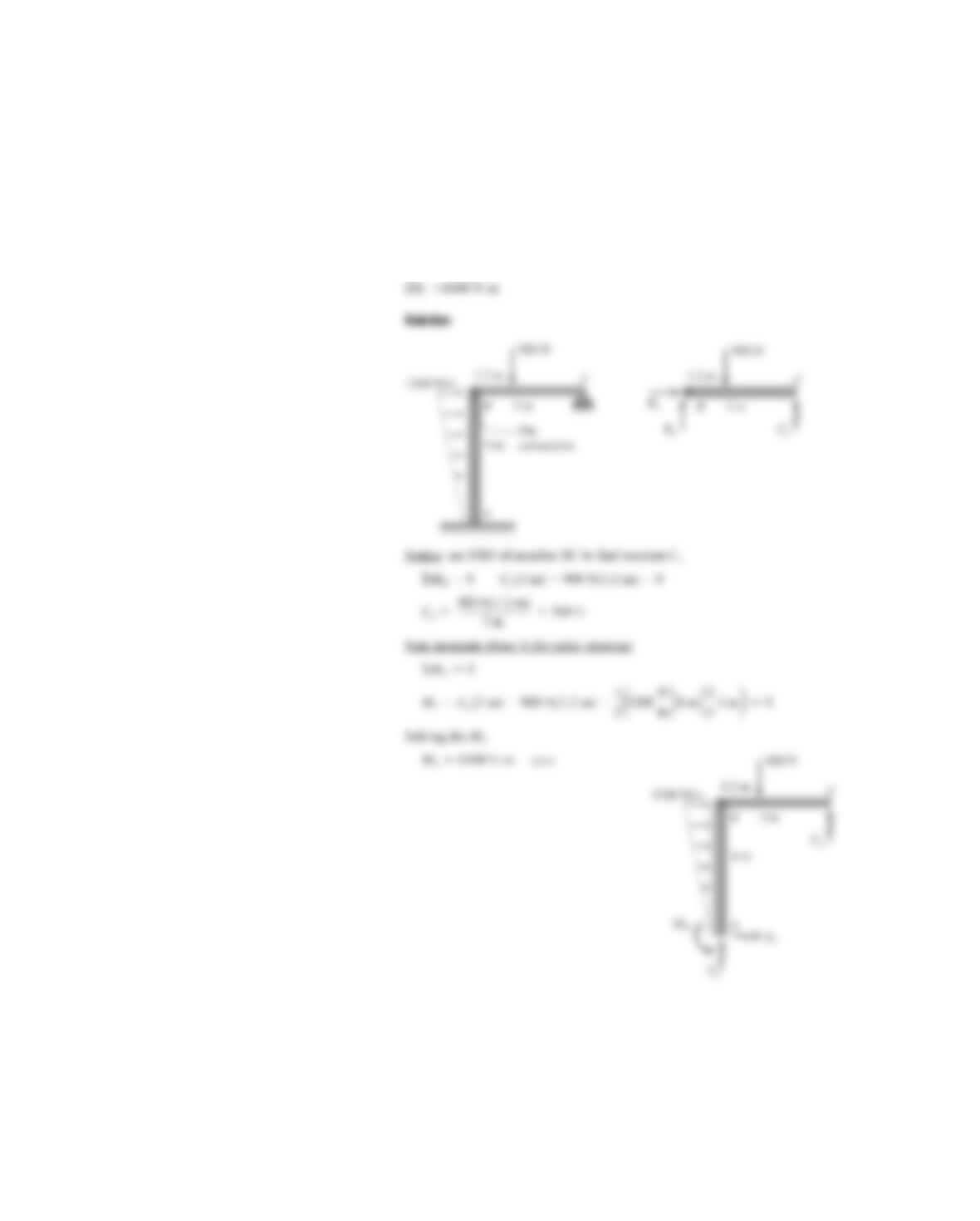
A-1.3: The moment reaction at Ain the plane frame below is approximately:
(A)
(B)
(C)
(D)
Solution
6400 Nm
3600 Nm
2280 Nm
1400 Nm
APPENDIX A FE Exam Review Problems 1085
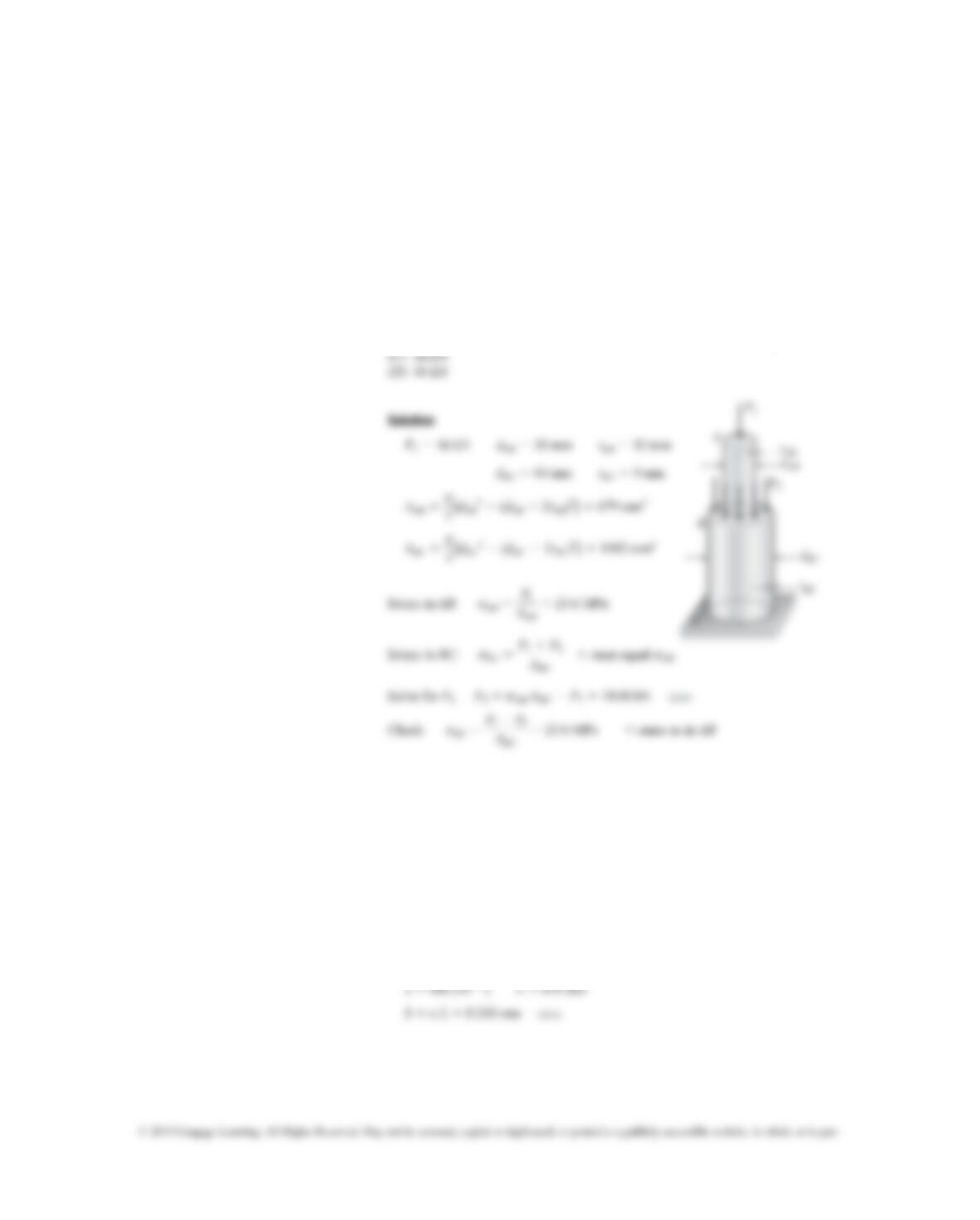
A-1.4: A hollow circular post ABC (see figure) supports a load P
1
16 kN
acting at the top. A second load P
2
is uniformly distributed around the cap plate
at B. The diameters and thicknesses of the upper and lower parts of the post are
d
AB
30 mm, t
AB
12 mm, d
BC
60 mm, and t
BC
9 mm, respectively. The
lower part of the post must have the same compressive stress as the upper part.
The required magnitude of the load P
2
is approximately:
(A) 18 kN
(B) 22 kN
(C) 28 kN
(D) 46 kN
A-1.5: A circular aluminum tube of length L650 mm is loaded in com-
pression by forces P. The outside and inside diameters are 80 mm and 68 mm,
respectively. A strain gage on the outside of the bar records a normal strain
in the longitudinal direction of 400 10
6
. The shortening of the bar is
approximately:
(A) 0.12 mm
(B) 0.26 mm
(C) 0.36 mm
(D) 0.52 mm
1086 APPENDIX A FE Exam Review Problems
78572_app_ptg01_hr_1083-1168.qxd 1/24/12 12:15 PM Page 1086
APPENDIX A FE Exam Review Problems 1087
A-1.6: A steel plate weighing 27 kN is hoisted by a cable sling that has a clevis
at each end. The pins through the clevises are 22 mm in diameter. Each half of
the cable is at an angle of to the vertical. The average shear stress in each pin
is approximately:
(A) 22 MPa
(B) 28 MPa
(C) 40 MPa
(D) 48 MPa
A-1.7: A steel wire hangs from a high-altitude balloon. The steel has unit weight
77kN/m
3
and yield stress of 280 MPa. The required factor of safety against yield
is 2.0. The maximum permissible length of the wire is approximately:
(A) 1800 m
(B) 2200 m
(C) 2600 m
(D) 3000 m
35
Solution
A-1.8: An aluminum bar (E72 GPa, 0.33) of diameter 50 mm cannot
exceed a diameter of 50.1 mm when compressed by axial force P. The maximum
acceptable compressive load Pis approximately:
(A) 190 kN
(B) 200 kN
(C) 470 kN
(D) 860 kN
Solution
A-1.9: An aluminum bar (E70 GPa, 0.33) of diameter 20 mm is stretched
by axial forces P, causing its diameter to decrease by 0.022 mm. The load Pis
approximately:
(A) 73 kN
(B) 100 kN
(C) 140 kN
(D) 339 kN
1088 APPENDIX A FE Exam Review Problems
78572_app_ptg01_hr_1083-1168.qxd 1/24/12 12:15 PM Page 1088
APPENDIX A FE Exam Review Problems 1089
Solution
A-1.10: A polyethylene bar (E1.4 GPa, 0.4) of diameter 80 mm is
inserted in a steel tube of inside diameter 80.2 mm and then compressed by axial
force P. The gap between steel tube and polyethylene bar will close when com-
pressive load Pis approximately:
(A) 18 kN
(B) 25 kN
(C) 44 kN
(D) 60 kN
Solution
1090 APPENDIX A FE Exam Review Problems
A-1.11: A pipe (E110 GPa) carries a load P
1
120 kN at Aand a uniformly
distributed load P
2
100 kN on the cap plate at B. Initial pipe diameters and
thicknesses are: d
AB
38 mm, t
AB
12 mm, d
BC
70 mm, t
BC
10 mm.
Under loads P
1
and P
2
, wall thickness t
BC
increases by 0.0036 mm. Poisson’s
ratio vfor the pipe material is approximately:
(A) 0.27
(B) 0.30
(C) 0.31
(D) 0.34
Solution
78572_app_ptg01_hr_1083-1168.qxd 1/24/12 12:15 PM Page 1090
APPENDIX A FE Exam Review Problems 1091
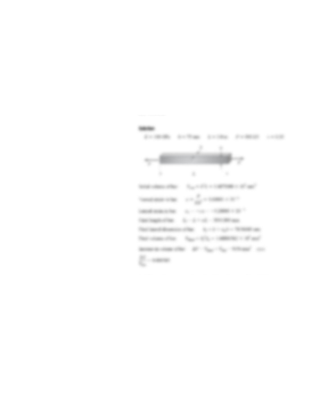
A-1.12: A titanium bar (E100 GPa, v0.33) with square cross section
(b75 mm) and length L3.0 m is subjected to tensile load P900 kN. The
increase in volume of the bar is approximately:
(A) 1400 mm
3
(B) 3500 mm
3
(C) 4800 mm
3
(D) 9200 mm
3
Solution
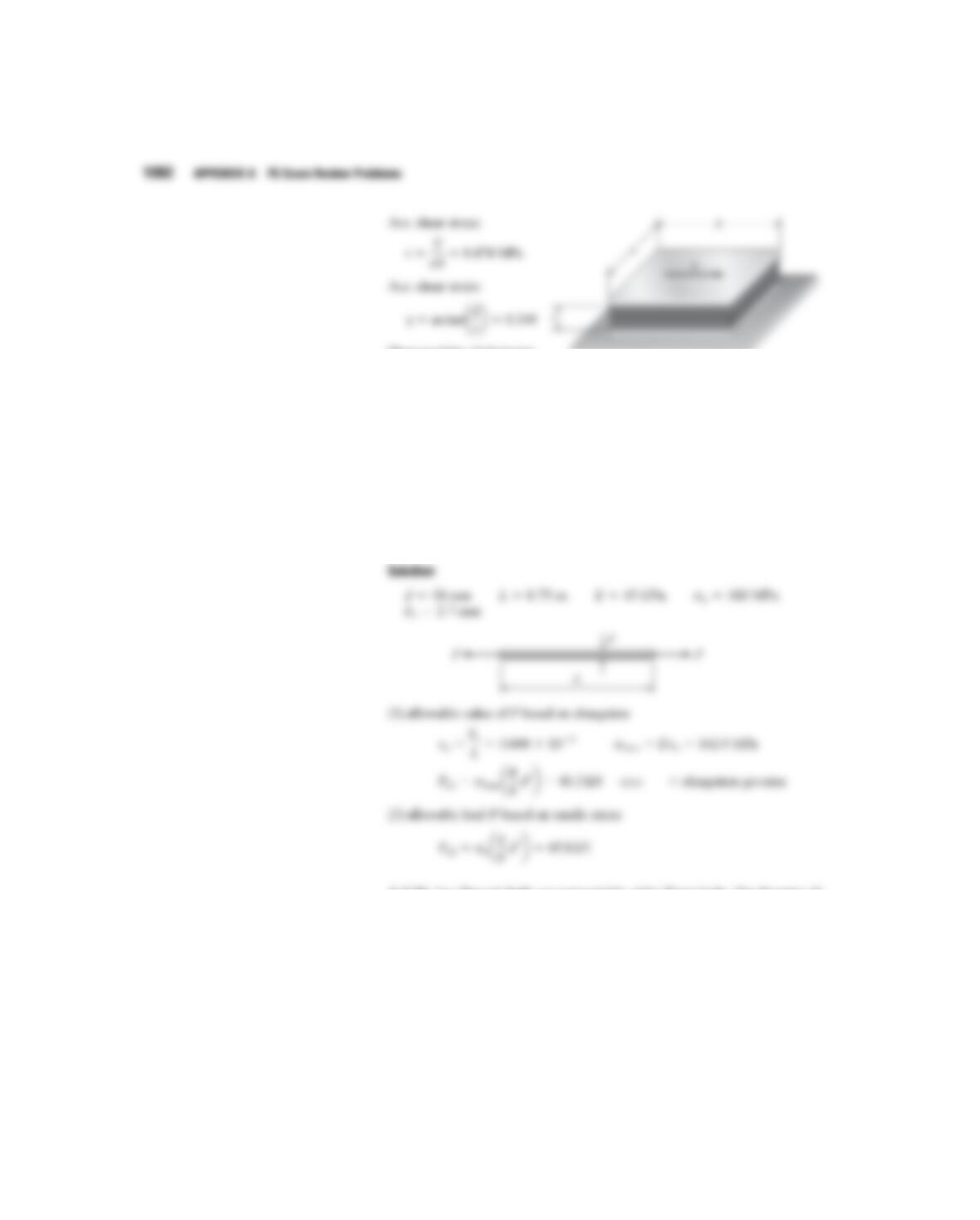
A-1.13: An elastomeric bearing pad is subjected to a shear force Vduring a static
loading test. The pad has dimensions a150 mm and b225 mm, and thick-
ness t55 mm. The lateral displacement of the top plate with respect to the
bottom plate is 14 mm under a load V16 kN. The shear modulus of elasticity
Gof the elastomer is approximately:
(A) 1.0 MPa
(B) 1.5 MPa
(C) 1.7 MPa
(D) 1.9 MPa
1092 APPENDIX A FE Exam Review Problems
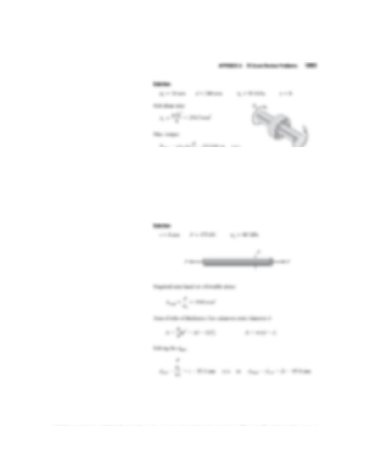
A-1.15: Two flanged shafts are connected by eight 18 mm bolts. The diameter of
the bolt circle is 240 mm. The allowable shear stress in the bolts is 90 MPa.
Ignore friction between the flange plates. The maximum value of torque T
0
is
approximately:
(A) 19 kNm
(B) 22 kNm
(C) 29 kNm
(D) 37 kNm
A-1.14: A bar of diameter d18 mm and length L0.75 m is loaded in ten-
sion by forces P. The bar has modulus E45 GPa and allowable normal stress
of 180 MPa. The elongation of the bar must not exceed 2.7 mm. The allowable
value of forces Pis approximately:
(A) 41 kN
(B) 46 kN
(C) 56 kN
(D) 63 kN
Solution
78572_app_ptg01_hr_1083-1168.qxd 1/24/12 12:15 PM Page 1092
APPENDIX A FE Exam Review Problems 1093
Solution
A-1.16: A copper tube with wall thickness of 8 mm must carry an axial tensile
force of 175 kN. The allowable tensile stress is 90 MPa. The minimum required
outer diameter is approximately:
(A) 60 mm
(B) 72 mm
(C) 85 mm
(D) 93 mm
Solution
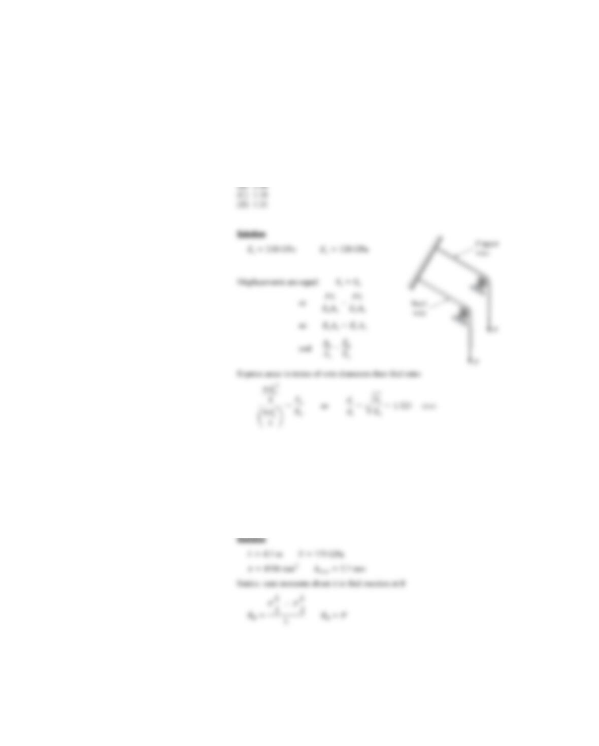
A-2.1: Two wires, one copper and the other steel, of equal length stretch the same
amount under an applied load P. The moduli of elasticity for each is: E
s
210 GPa,
E
c
120 GPa. The ratio of the diameter of the copper wire to that of the steel wire
is approximately:
(A) 1.00
(B) 1.08
(C) 1.19
(D) 1.32
A-2.2: A plane truss with span length L4.5 m is constructed using cast iron pipes
(E170 GPa) with cross sectional area of 4500 mm
2
. The displacement of joint B
cannot exceed 2.7 mm. The maximum value of loads Pis approximately:
(A) 340 kN
(B) 460 kN
(C) 510 kN
(D) 600 kN
1094 APPENDIX A FE Exam Review Problems
78572_app_ptg01_hr_1083-1168.qxd 1/24/12 12:15 PM Page 1094
APPENDIX A FE Exam Review Problems 1095
A-2.3: A brass rod (E110 GPa) with cross sectional area of 250 mm
2
is loaded
by forces P
1
15 kN, P
2
10 kN, and P
3
8 kN. Segment lengths of the bar
are a2.0 m, b0.75 m, and c1.2 m. The change in length of the bar is
approximately:
(A) 0.9 mm
(B) 1.6 mm
(C) 2.1 mm
(D) 3.4 mm
Solution
1096 APPENDIX A FE Exam Review Problems
A-2.4: A brass bar (E 110 MPa)of length L2.5 m has diameter d
1
18 mm
over one-half of its length and diameter d
2
12 mm over the other half. Compare
this nonprismatic bar to a prismatic bar of the same volume of material with
constant diameter dand length L. The elongation of the prismatic bar under the
same load P 25 kN is approximately:
(A) 3 mm
(B) 4 mm
(C) 5 mm
(D) 6 mm
Solution
78572_app_ptg01_hr_1083-1168.qxd 1/24/12 12:15 PM Page 1096
APPENDIX A FE Exam Review Problems 1097
A-2.5: A nonprismatic cantilever bar has an internal cylindrical hole of diameter
d/2 from 0 to x, so the net area of the cross section for Segment 1 is (3/4)A. Load
Pis applied at x, and load –P/2 is applied at xL. Assume that Eis constant. The
length of the hollow segment, x, required to obtain axial displacement
dPL/EA at the free end is:
(A) xL/5
(B) xL/4
(C) xL/3
(D) x3L/5
Solution
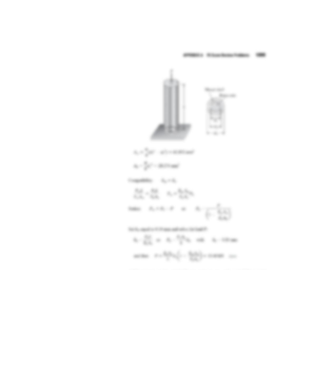
A-2.6: A nylon bar (E2.1 GPa) with diameter 12 mm, length 4.5 m, and
weight 5.6 N hangs vertically under its own weight. The elongation of the bar at
its free end is approximately:
(A) 0.05 mm
(B) 0.07 mm
(C) 0.11 mm
(D) 0.17 mm
Solution
A-2.7: A monel shell (E
m
170 GPa, d
3
12 mm, d
2
8 mm) encloses a brass
core (E
b
96 GPa, d
1
6 mm). Initially, both shell and core are of length 100 mm.
A load Pis applied to both shell and core through a cap plate. The load P
required to compress both shell and core by 0.10 mm is approximately:
(A) 10.2 kN
(B) 13.4 kN
(C) 18.5 kN
(D) 21.0 kN
Solution
1098 APPENDIX A FE Exam Review Problems
78572_app_ptg01_hr_1083-1168.qxd 1/24/12 12:15 PM Page 1098
APPENDIX A FE Exam Review Problems 1099
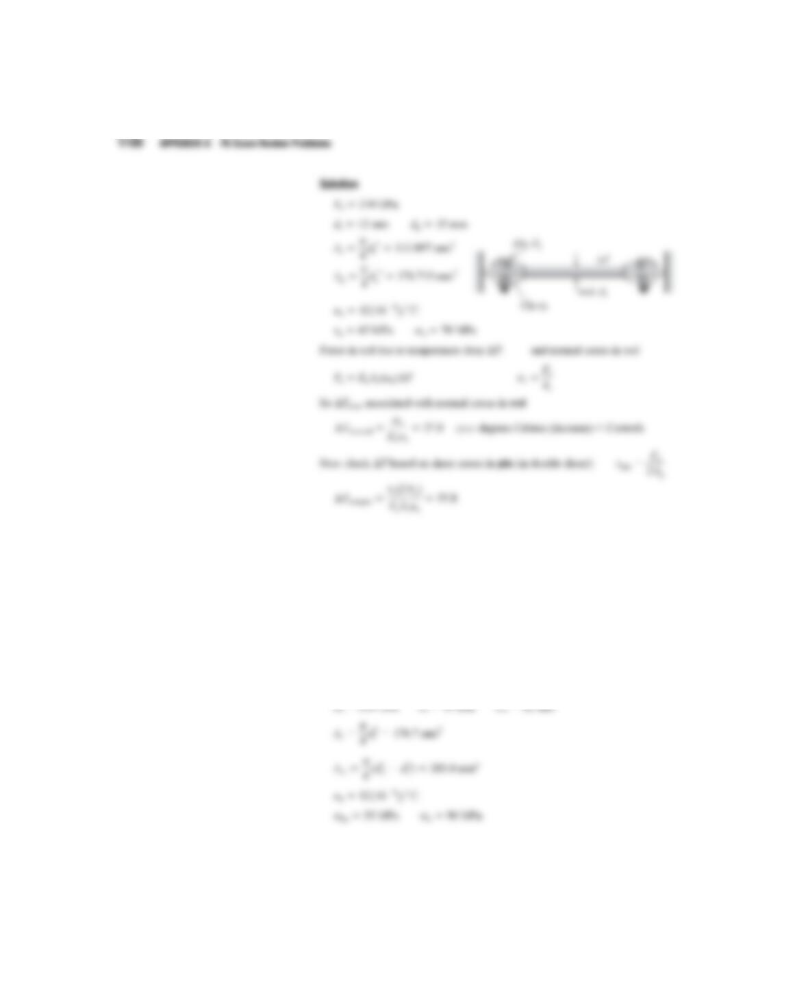
A-2.8: A steel rod (E
s
210 GPa, d
r
12 mm, ) is held
stress free between rigid walls by a clevis and pin (d
p
15 mm) assembly at each
end. If the allowable shear stress in the pin is 45 MPa and the allowable normal
stress in the rod is 70 MPa, the maximum permissible temperature drop Tis
approximately:
(A) 14
(B) 20
(C) 28
(D) 40 C
C
C
C
a
s
12 10
6
> C
1100 APPENDIX A FE Exam Review Problems
Solution
A-2.9: A threaded steel rod (E
s
210 GPa, d
r
15 mm,
s
12 10
6
)
is held stress free between rigid walls by a nut and washer (d
w
22 mm)
assembly at each end. If the allowable bearing stress between the washer and
wall is 55 MPa and the allowable normal stress in the rod is 90 MPa, the
maximum permissible temperature drop Tis approximately:
(A) 25
(B) 30
(C) 38
(D) 46
Solution
C
C
C
C
> C
78572_app_ptg01_hr_1083-1168.qxd 1/24/12 12:15 PM Page 1100
APPENDIX A FE Exam Review Problems 1101
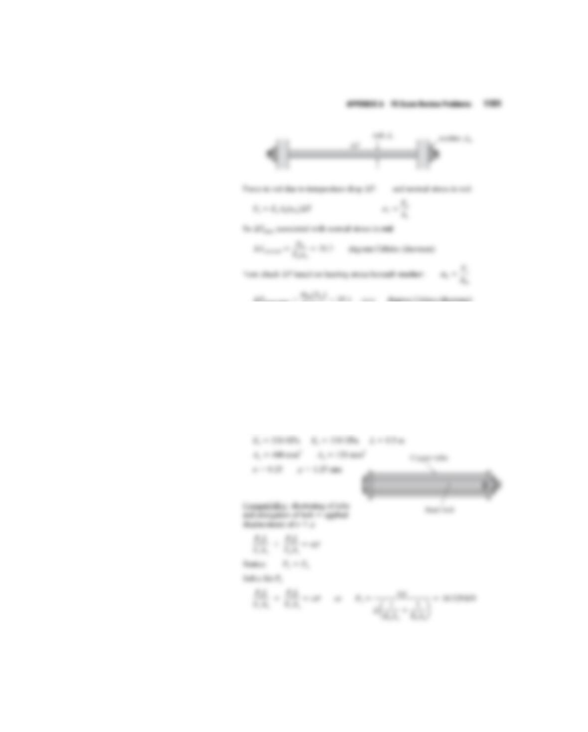
A-2.10: A steel bolt (area 130 mm
2
, E
s
210 GPa) is enclosed by a copper tube
(length 0.5 m, area 400 mm
2
, E
c
110 GPa) and the end nut is turned until
it is just snug. The pitch of the bolt threads is 1.25 mm. The bolt is now tightened
by a quarter turn of the nut. The resulting stress in the bolt is approximately:
(A) 56 MPa
(B) 62 MPa
(C) 74 MPa
(D) 81 MPa
Solution
1102 APPENDIX A FE Exam Review Problems
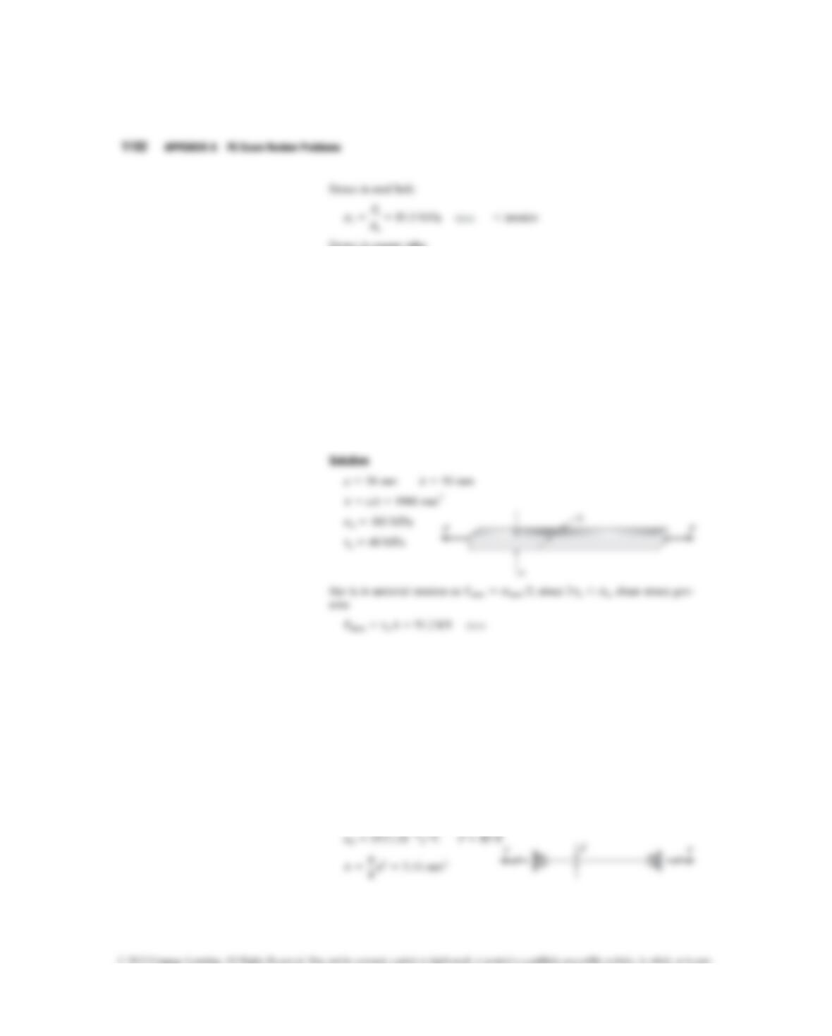
A-2.11: A steel bar of rectangular cross section (a38 mm, b50 mm)
carries a tensile load P. The allowable stresses in tension and shear are
100 MPa and 48 MPa respectively. The maximum permissible load P
max
is
approximately:
(A) 56 kN
(B) 62 kN
(C) 74 kN
(D) 91 kN
Solution
A-2.12: A brass wire (d2.0 mm, E110 GPa) is pretensioned to T85 N.
The coefficient of thermal expansion for the wire is 19.5 10
6
. The tem-
perature change at which the wire goes slack is approximately:
(A) 5.7
(B) 12.6
(C) 12.6
(D) 18.2
Solution
C
C
C
C> C
78572_app_ptg01_hr_1083-1168.qxd 1/24/12 12:15 PM Page 1102
APPENDIX A FE Exam Review Problems 1103
A-2.13: A copper bar (d10 mm, E110 GPa) is loaded by tensile load
P11.5 kN. The maximum shear stress in the bar is approximately:
(A) 73 MPa
(B) 87 MPa
(C) 145 MPa
(D) 150 MPa
Solution
A-2.14: A steel plane truss is loaded at Band Cby forces P200 kN. The cross
sectional area of each member is A3970 mm
2
. Truss dimensions are H3 m
and L4 m. The maximum shear stress in bar AB is approximately:
(A) 27 MPa
(B) 33 MPa
(C) 50 MPa
(D) 69 MPa
Solution
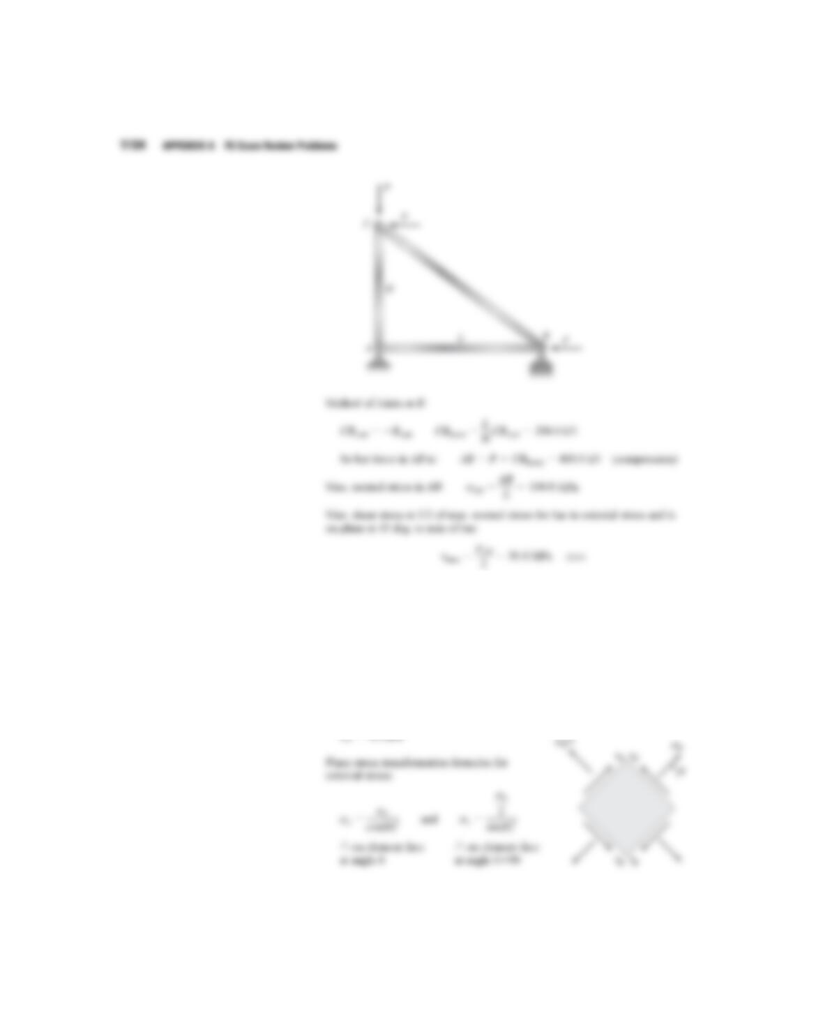
A-2.15: A plane stress element on a bar in uniaxial stress has tensile stress of
s
78 MPa (see fig.). The maximum shear stress in the bar is approximately:
(A) 29 MPa
(B) 37 MPa
(C) 50 MPa
(D) 59 MPa
Solution
1104 APPENDIX A FE Exam Review Problems
78572_app_ptg01_hr_1083-1168.qxd 1/24/12 12:15 PM Page 1104
APPENDIX A FE Exam Review Problems 1105
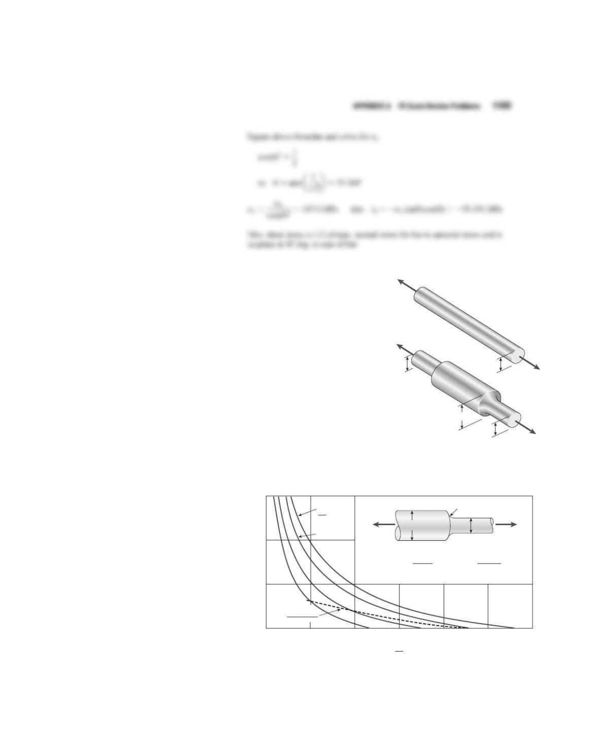
A-2.16: A prismatic bar (diameter
) is loaded by force P
1
.
A stepped bar (diameters
with radius Rof fillets
) is loaded by force P
2
. The
allowable axial stress in the material is
75 MPa. The ratio of the max-
imum permissible loads that can be
applied to the bars, considering stress
concentration effects in the stepped
bar, is:
(A) 0.9
(B) 1.2
(C) 1.4
(D) 2.1
P
1
/P
2
2 mm
d
2
25 mm,
d
1
20 mm,
d
0
18 mm
P1
P2
d1
d0
d1
d2
P2
P1
FIG. 2-66 Stress-concentration factor Kfor round bars with shoulder fillets.
The dashed line is for a full quater-circular fillet.
K
0 0.05 0.10
1.1
1.2
1.5
0.15 0.20 0.25 0.30
3.0
2.5
2.0
1.5
R
D1
K = P
1/4 D2
max
nom nom =
D2 – D1
2
R =
= 2 P
R
P
D1
D2
D1D2
s
ss
p
Solution
1106 APPENDIX A FE Exam Review Problems
A-3.1: A brass rod of length L0.75 m is twisted by torques Tuntil the angle
of rotation between the ends of the rod is 3.5°. The allowable shear strain in
the copper is 0.0005 rad. The maximum permissible diameter of the rod is
approximately:
(A) 6.5 mm
(B) 8.6 mm
(C) 9.7 mm
(D) 12.3 mm
Solution
78572_app_ptg01_hr_1083-1168.qxd 1/24/12 12:15 PM Page 1106
APPENDIX A FE Exam Review Problems 1107
A-3.2: The angle of rotation between the ends of a nylon bar is 3.5°. The bar
diameter is 70 mm and the allowable shear strain is 0.014 rad. The minimum
permissible length of the bar is approximately:
(A) 0.15 m
(B) 0.27 m
(C) 0.40 m
(D) 0.55 m
Solution
A-3.3: A brass bar twisted by torques Tacting at the ends has the following
properties: L2.1 m, d38 mm, and G41 GPa. The torsional stiffness of the
bar is approximately:
(A) 1200 Nm
(B) 2600 Nm
(C) 4000 Nm
(D) 4800 Nm
Solution
A-3.4: A brass pipe is twisted by torques T 800 Nm acting at the ends causing
an angle of twist of 3.5 degrees. The pipe has the following properties: L 2.1 m,
d
1
38 mm, and d
2
56 mm. The shear modulus of elasticity Gof the pipe is
approximately:
(A) 36.1 GPa
(B) 37.3 GPa
(C) 38.7 GPa
(D) 40.6 GPa
Solution
1108 APPENDIX A FE Exam Review Problems
A-3.5: An aluminum bar of diameter d52 mm is twisted by torques T
1
at the
ends. The allowable shear stress is 65 MPa. The maximum permissible torque T
1
is approximately:
(A) 1450 Nm
(B) 1675 Nm
(C) 1710 Nm
(D) 1800 Nm
Solution
A-3.6: A steel tube with diameters d
2
86 mm and d
1
52 mm is twisted by
torques at the ends. The diameter of a solid steel shaft that resists the same torque
at the same maximum shear stress is approximately:
(A) 56 mm
(B) 62 mm
(C) 75 mm
(D) 82 mm
78572_app_ptg01_hr_1083-1168.qxd 1/24/12 12:15 PM Page 1108
APPENDIX A FE Exam Review Problems 1109
Solution
A-3.7: A stepped steel shaft with diameters d
1
56 mm and d
2
52 mm is
twisted by torques T
1
3.5 kNm and T
2
1.5 kNm acting in opposite direc-
tions. The maximum shear stress is approximately:
(A) 54 MPa
(B) 58 MPa
(C) 62 MPa
(D) 79 MPa
Solution
A-3.8: A stepped steel shaft (G75 GPa) with diameters d
1
36 mm and
d
2
32 mm is twisted by torques Tat each end. Segment lengths are L
1
0.9 m
and L
2
0.75 m. If the allowable shear stress is 28 MPa and maximum allow-
able twist is 1.8 degrees, the maximum permissible torque is approximately:
(A) 142 Nm
(B) 180 Nm
(C) 185 Nm
(D) 257 Nm
Solution
1110 APPENDIX A FE Exam Review Problems
78572_app_ptg01_hr_1083-1168.qxd 1/24/12 12:15 PM Page 1110
APPENDIX A FE Exam Review Problems 1111
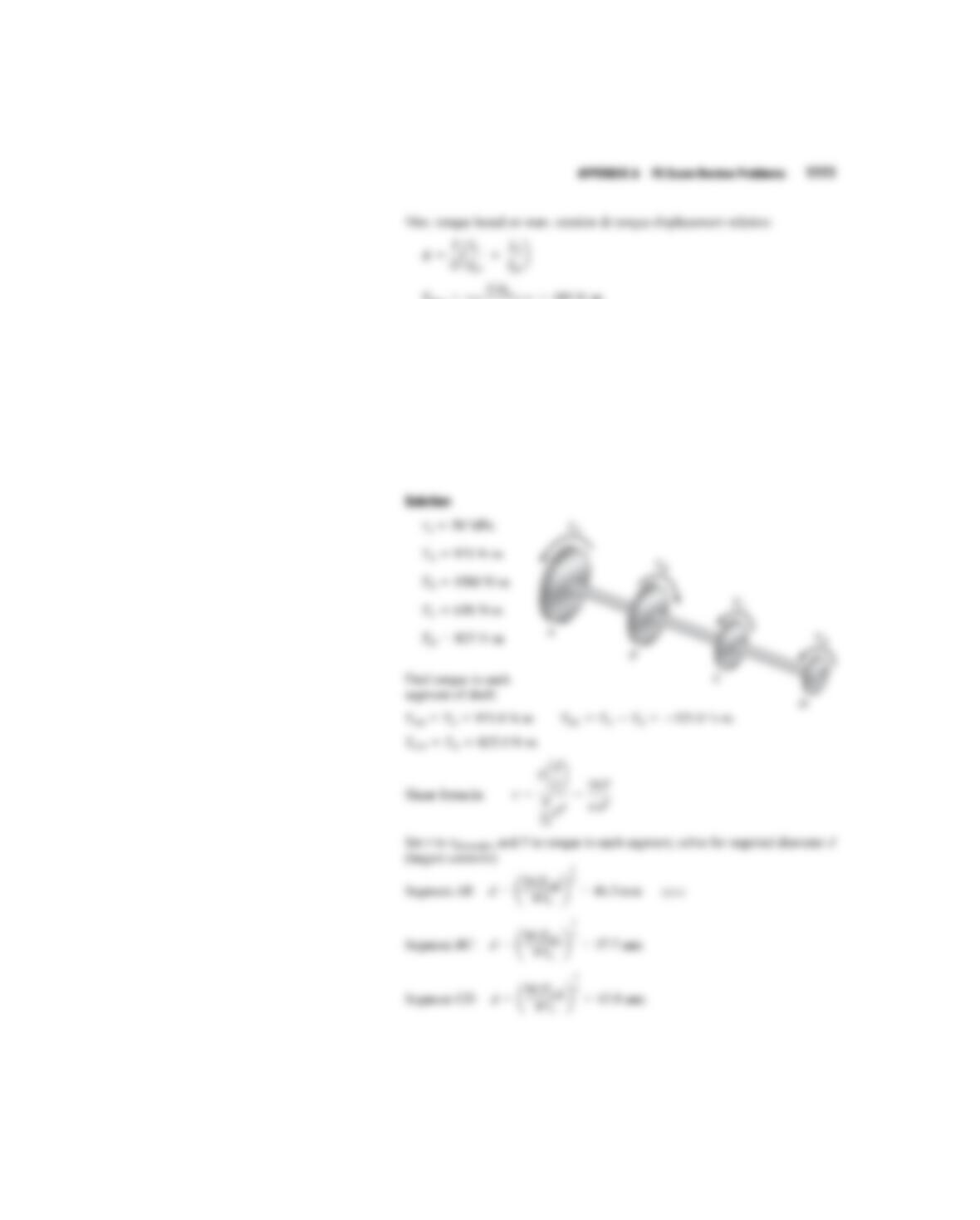
A-3.9: A gear shaft transmits torques T
A
975 Nm, T
B
1500 Nm, T
C
650 Nm and T
D
825 Nm. If the allowable shear stress is 50 MPa, the
required shaft diameter is approximately:
(A) 38 mm
(B) 44 mm
(C) 46 mm
(D) 48 mm
Solution
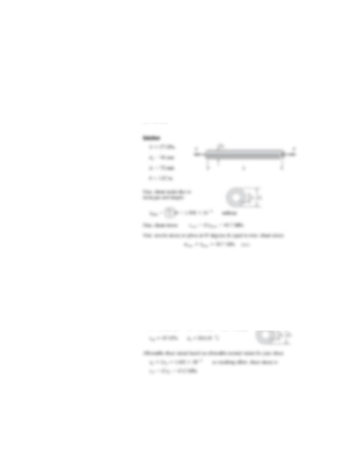
A-3.10: A hollow aluminum shaft (G27 GPa, d
2
96 mm, d
1
52 mm)
has an angle of twist per unit length of 1.8°/mdue to torques T. The resulting
maximum tensile stress in the shaft is approximately:
(A) 38 MPa
(B) 41 MPa
(C) 49 MPa
(D) 58 MPa
Solution
A-3.11: Torques T5.7 kNm are applied to a hollow aluminum shaft (G
27 GPa, d
1
52 mm). The allowable shear stress is 45 MPa and the allowable
normal strain is 8.0 10
4
. The required outside diameter d
2
of the shaft is
approximately:
(A) 38 mm
(B) 56 mm
(C) 87 mm
(D) 91 mm
Solution
1112 APPENDIX A FE Exam Review Problems
78572_app_ptg01_hr_1083-1168.qxd 1/24/12 12:15 PM Page 1112
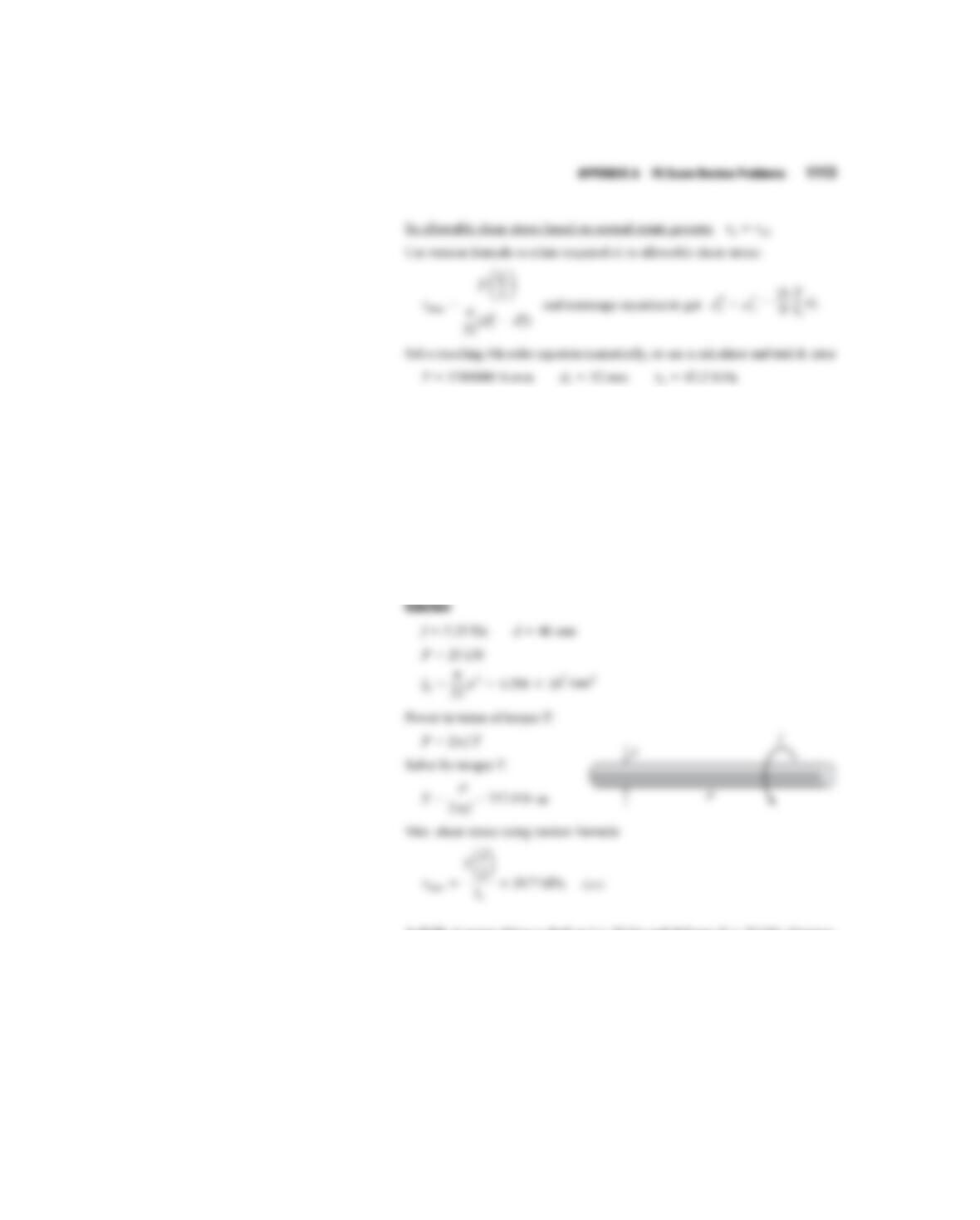
A-3.12: A motor drives a shaft with diameter d46 mm at f5.25 Hz
and delivers P25 kW of power. The maximum shear stress in the shaft is
approximately:
(A) 32 MPa
(B) 40 MPa
(C) 83 MPa
(D) 91 MPa
Solution
A-3.13: A motor drives a shaft at f10 Hz and delivers P35 kW of power.
The allowable shear stress in the shaft is 45 MPa. The minimum diameter of the
shaft is approximately:
(A) 35 mm
(B) 40 mm
(C) 47 mm
(D) 61 mm
APPENDIX A FE Exam Review Problems 1113
Solution
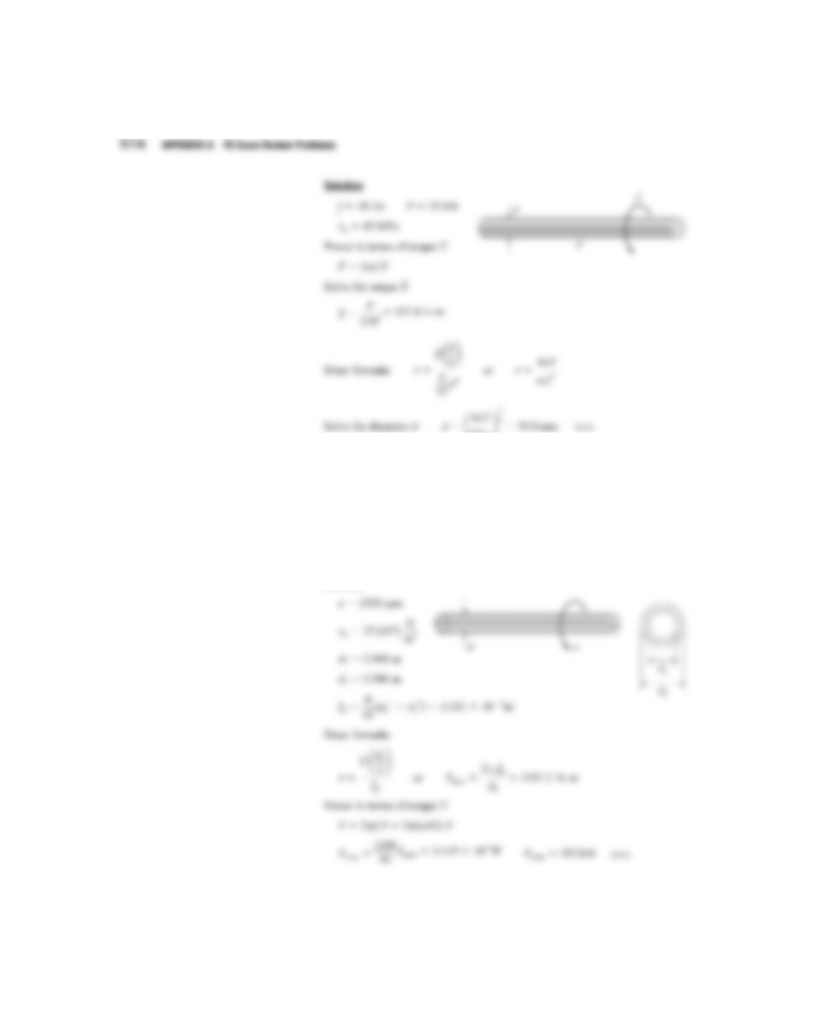
A-3.14: A drive shaft running at 2500 rpm has outer diameter 60 mm and inner
diameter 40 mm. The allowable shear stress in the shaft is 35 MPa. The maximum
power that can be transmitted is approximately:
(A) 220 kW
(B) 240 kW
(C) 288 kW
(D) 312 kW
Solution
1114 APPENDIX A FE Exam Review Problems
78572_app_ptg01_hr_1083-1168.qxd 1/24/12 12:15 PM Page 1114
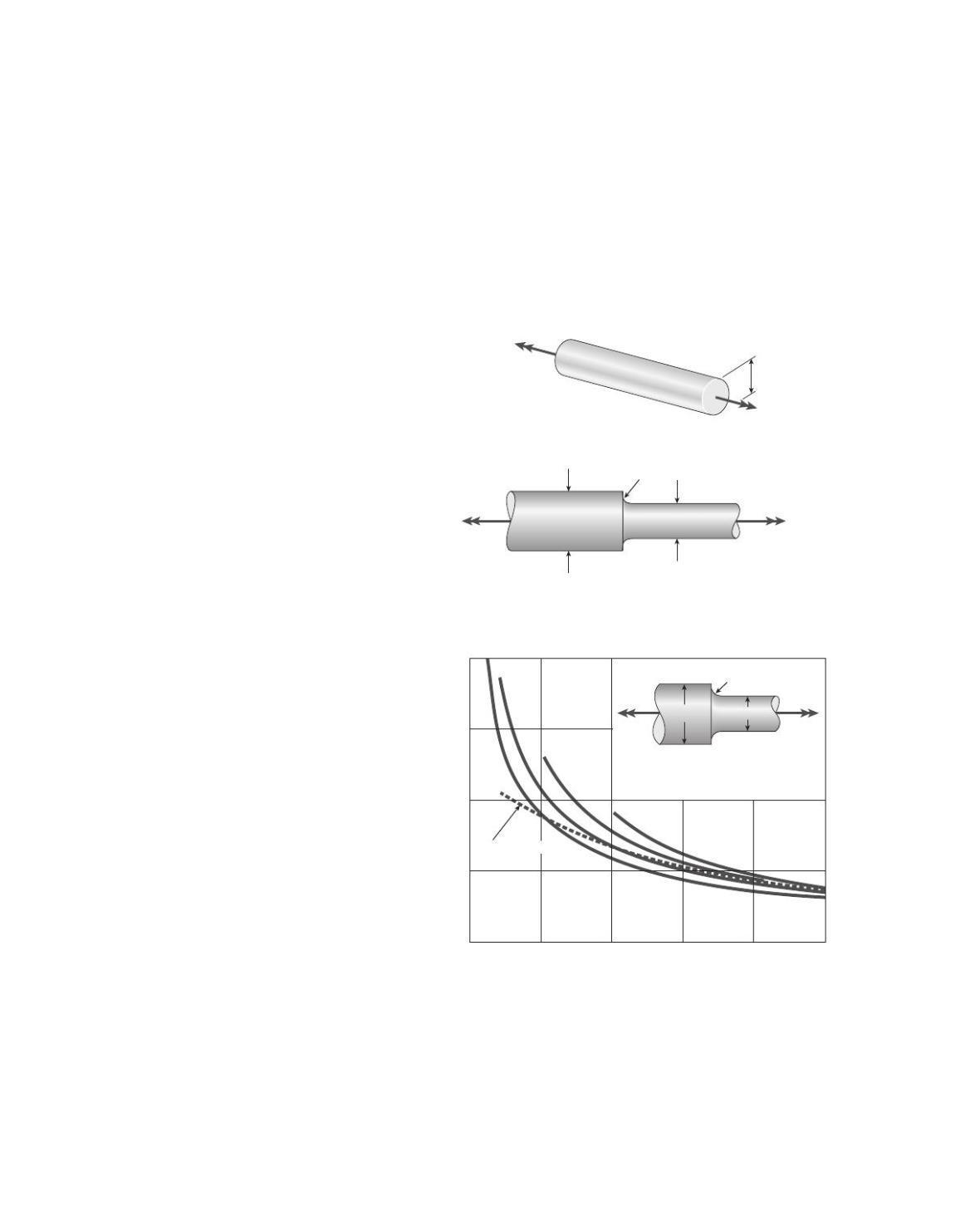
A-3.15: A prismatic shaft (diameter ) is loaded by torque T
1
.
A stepped shaft (diameters radius Rof fillets
) is loaded by torque T
2
. The allowable shear stress in the material is 42
MPa. The ratio of the maximum permissible torques that can be applied to
the shafts, considering stress concentration effects in the stepped shaft is:
(A) 0.9
(B) 1.2
(C) 1.4
(D) 2.1
T
1
/T
2
2 mm
d
2
25 mm,d
1
20 mm,
d
0
19 mm
APPENDIX A FE Exam Review Problems 1115
T1
T1
d0
R
T2T2
D2D1
FIG. 3-59 Stress-concentration factor Kfor a stepped shaft in torsion. (The
dashed line is for a full quarter-circular fillet.)
K
0
1.00
1.50
2.00
0.10
1.5
1.2
1.1
0.20
D2D1
T
R
T
t
max = Kt
nom t
nom = 16T
D1
3
——
=2
D1
D2
—–
D1
R
—–
=+ 2R
D1
D2
p
1116 APPENDIX A FE Exam Review Problems
Solution
A-4.1: A simply supported beam with proportional loading (P4.1 kN) has
span length L5 m. Load Pis 1.2 m from support Aand load 2Pis 1.5 m from
support B. The bending moment just left of load 2Pis approximately:
(A) 5.7 kNm
(B) 6.2 kNm
(C) 9.1 kNm
(D) 10.1 kNm
Solution
78572_app_ptg01_hr_1083-1168.qxd 1/24/12 12:15 PM Page 1116
Solution
A-4.3: A cantilever beam is loaded as shown in the figure. The bending moment
at 0.5 m from the support is approximately:
(A) 12.7 kNm
(B) 14.2 kNm
(C) 16.1 kNm
(D) 18.5 kNm
Solution
APPENDIX A FE Exam Review Problems 1117
A-4.4: An L-shaped beam is loaded as shown in the figure. The bending moment
at the midpoint of span AB is approximately:
(A) 6.8 kNm
(B) 10.1 kNm
(C) 12.3 kNm
(D) 15.5 kNm
1118 APPENDIX A FE Exam Review Problems
Solution
A-4.5: A T-shaped simple beam has a cable with force Panchored at Band
passing over a pulley at Eas shown in the figure. The bending moment just left
of Cis 1.25 kNm. The cable force Pis approximately:
(A) 2.7 kN
(B) 3.9 kN
(C) 4.5 kN
(D) 6.2 kN
Solution
78572_app_ptg01_hr_1083-1168.qxd 1/24/12 12:15 PM Page 1118
A-4.6: A simple beam (L9 m) with attached bracket BDE has force P5 kN
applied downward at E. The bending moment just right of Bis approximately:
(A) 6 kNm
(B) 10 kNm
(C) 19 kNm
(D) 22 kNm
Solution
A-4.7: A simple beam AB with an overhang BC is loaded as shown in the figure.
The bending moment at the midspan of AB is approximately:
(A) 8 kNm
(B) 12 kNm
(C) 17 kNm
(D) 21 kNm
Solution
APPENDIX A FE Exam Review Problems 1119
A-5.1: A copper wire (d1.5 mm) is bent around a tube of radius R0.6 m.
The maximum normal strain in the wire is approximately:
(A) 1.25 10
3
(B) 1.55 10
3
(C) 1.76 10
3
(D) 1.92 10
3
Solution
A-5.2: A simply supported wood beam (L5 m) with rectangular cross section
(b200 mm, h280 mm) carries uniform load q6.5 kN/m which includes
the weight of the beam. The maximum flexural stress is approximately:
(A) 8.7 MPa
(B) 10.1 MPa
(C) 11.4 MPa
(D) 14.3 MPa
1120 APPENDIX A FE Exam Review Problems
78572_app_ptg01_hr_1083-1168.qxd 1/24/12 12:15 PM Page 1120
A-5.3: A cast iron pipe (L12 m, weight density 72 kN/m
3
, d
2
100 mm,
d
1
75 mm) is lifted by a hoist. The lift points are 6 m apart. The maximum
bending stress in the pipe is approximately:
(A) 28 MPa
(B) 33 MPa
(C) 47 MPa
(D) 59 MPa
Solution
APPENDIX A FE Exam Review Problems 1121
A-5.4: A beam with an overhang is loaded by a uniform load of 3 kN/m over its
entire length. Moment of inertia I
z
3.36 10
6
mm
4
and distances to top and
bottom of the beam cross section are 20 mm and 66.4 mm, respectively. It is
known that reactions at Aand Bare 4.5 kN and 13.5 kN, respectively. The
maximum bending stress in the beam is approximately:
(A) 36 MPa
(B) 67 MPa
(C) 102 MPa
(D) 119 MPa
Solution
1122 APPENDIX A FE Exam Review Problems
78572_app_ptg01_hr_1083-1168.qxd 1/24/12 12:15 PM Page 1122
A-5.5: A steel hanger with solid cross section has horizontal force P5.5 kN
applied at free end D. Dimension variable b175 mm and allowable normal
stress is 150 MPa. Neglect self weight of the hanger. The required diameter of
the hanger is approximately:
(A) 5 cm
(B) 7 cm
(C) 10 cm
(D) 13 cm
Solution
APPENDIX A FE Exam Review Problems 1123
A-5.6: A cantilever wood pole carries force P300 N applied at its free end, as
well as its own weight (weight density 6 kN/m
3
). The length of the pole is
L0.75 m and the allowable bending stress is 14 MPa. The required diameter
of the pole is approximately:
(A) 4.2 cm
(B) 5.5 cm
(C) 6.1 cm
(D) 8.5 cm
Solution
1124 APPENDIX A FE Exam Review Problems
78572_app_ptg01_hr_1083-1168.qxd 1/24/12 12:15 PM Page 1124
A-5.7: A simply supported steel beam of length L1.5 m and rectangular cross
section (h75 mm, b20 mm) carries a uniform load of q48 kN/m, which
includes its own weight. The maximum transverse shear stress on the cross sec-
tion at 0.25 m from the left support is approximately:
(A) 20 MPa
(B) 24 MPa
(C) 30 MPa
(D) 36 MPa
Solution
A-5.8: A simply supported laminated beam of length L0.5 m and square cross
section weighs 4.8 N. Three strips are glued together to form the beam, with the
allowable shear stress in the glued joint equal to 0.3 MPa. Considering also the
weight of the beam, the maximum load Pthat can be applied at L/3 from the left
support is approximately:
(A) 240 N
(B) 360 N
(C) 434 N
(D) 510 N
APPENDIX A FE Exam Review Problems 1125
Solution
1126 APPENDIX A FE Exam Review Problems
A-5.9: An aluminum cantilever beam of length L0.65 m carries a distributed
load, which includes its own weight, of intensity q/2 at Aand qat B. The beam
cross section has width 50 mm and height 170 mm. Allowable bending stress is
95 MPa and allowable shear stress is 12 MPa. The permissible value of load
intensity qis approximately:
(A) 110 kN/m
(B) 122 kN/m
(C) 130 kN/m
(D) 139 kN/m
78572_app_ptg01_hr_1083-1168.qxd 1/24/12 12:15 PM Page 1126
Solution
A-5.10: An aluminum light pole weighs 4300 N and supports an arm of weight
700 N, with arm center of gravity at 1.2 m left of the centroidal axis of the pole.
A wind force of 1500 N acts to the right at 7.5 m above the base. The pole cross
section at the base has outside diameter 235 mm and thickness 20 mm. The
maximum compressive stress at the base is approximately:
(A) 16 MPa
(B) 18 MPa
(C) 21 MPa
(D) 24 MPa
APPENDIX A FE Exam Review Problems 1127
A-5.11: Two thin cables, each having diameter dt/6 and carrying tensile loads
P, are bolted to the top of a rectangular steel block with cross section dimensions
b t. The ratio of the maximum tensile to compressive stress in the block due
to loads Pis:
(A) 1.5
(B) 1.8
(C) 2.0
(D) 2.5
Solution
1128 APPENDIX A FE Exam Review Problems
78572_app_ptg01_hr_1083-1168.qxd 1/24/12 12:15 PM Page 1128
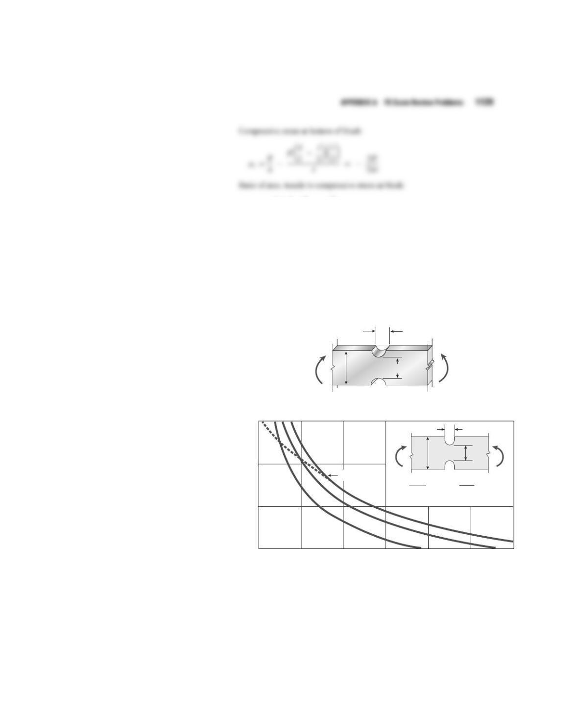
A-5.12: A rectangular beam with semicircular notches has dimen-
sions and . The maximum allowable bending stress
in the plastic beam is , and the bending moment is
. The minimum permissible width of the beam is:
(A) 12 mm
(B) 20 mm
(C) 28 mm
(D) 32 mm
M185 Nm
s
max
6.5 MPa
h
1
140 mmh160 mm
APPENDIX A FE Exam Review Problems 1129
h
=
h1 + 2R
R
—
h1
3.0
2.5
2.0
1.5
0 0.05 0.10 0.15 0.20 0.25 0.30
K
1.05
= 1.2
1.1
b = thickness
K = s max
s nom = 6M
bh
2
1
s nom
h1
h
MM
2R
h
h1
—
M
M
hh1
2R
FIG. 5-50 Stress-concentration factor Kfor a notched beam of rectangular
cross section in pure bending ( height of beam; thickness of beam,
perpendicular to the plane of the figure). The dashed line is for semicircular
notches ( )hh
1
2R
bh
Solution
1130 APPENDIX A FE Exam Review Problems
y
A-6.1: A composite beam is made up of a 200 mm 300 mm core (E
c
14 GPa)
and an exterior cover sheet (300 mm 12 mm, E
e
100 GPa) on each side.
Allowable stresses in core and exterior sheets are 9.5 MPa and 140 MPa, respec-
tively. The ratio of the maximum permissible bending moment about the z-axis to
that about the y-axis is most nearly:
(A) 0.5
(B) 0.7
(C) 1.2
(D) 1.5
78572_app_ptg01_hr_1083-1168.qxd 1/24/12 12:15 PM Page 1130
A-6.2: A composite beam is made up of a 90 mm 160 mm wood beam (E
w
11 GPa) and a steel bottom cover plate (90 mm 8 mm, E
s
190 GPa).
Allowable stresses in wood and steel are 6.5 MPa and 110 MPa, respectively.
The allowable bending moment about the z-axis of the composite beam is most
nearly:
(A) 2.9 kN?m
(B) 3.5 kN?m
(C) 4.3 kN?m
(D) 9.9 kN?m
APPENDIX A FE Exam Review Problems 1131
Solution
A-6.3: A steel pipe (d
3
104 mm, d
2
96 mm) has a plastic liner with inner
diameter d
1
82 mm. The modulus of elasticity of the steel is 75 times that of
the modulus of the plastic. Allowable stresses in steel and plastic are 40 MPa and
550 kPa, respectively. The allowable bending moment for the composite pipe is
approximately:
(A) 1100 N?m
(B) 1230 N?m
(C) 1370 N?m
(D) 1460 N?m
1132 APPENDIX A FE Exam Review Problems
78572_app_ptg01_hr_1083-1168.qxd 1/24/12 12:15 PM Page 1132
Solution
A-6.4: A bimetallic beam of aluminum (E
a
70 GPa) and copper (E
c
110 GPa)
strips has width b25 mm; each strip has thickness t1.5 mm. A bending
moment of 1.75 N?m is applied about the zaxis. The ratio of the maximum stress in
the aluminum to that in the copper is approximately:
(A) 0.6
(B) 0.8
(C) 1.0
(D) 1.5
APPENDIX A FE Exam Review Problems 1133
Solution
A-6.5: A composite beam of aluminum (E
a
72 GPa) and steel (E
s
190 GPa)
has width b25 mm and heights h
a
42 mm, h
s
68 mm. A bending moment
is applied about the zaxis resulting in a maximum stress in the aluminum of
55 MPa. The maximum stress in the steel is approximately:
(A) 86 MPa
(B) 90 MPa
(C) 94 MPa
(D) 98 MPa
1134 APPENDIX A FE Exam Review Problems
78572_app_ptg01_hr_1083-1168.qxd 1/24/12 12:15 PM Page 1134
APPENDIX A FE Exam Review Problems 1135
A-7.1: A rectangular plate (a120 mm, b160 mm) is subjected to com-
pressive stress s
x
4.5 MPa and tensile stress s
y
15 MPa. The ratio of the
normal stress acting perpendicular to the weld to the shear stress acting along the
weld is approximately:
(A) 0.27
(B) 0.54
(C) 0.85
(D) 1.22
Solution
1136 APPENDIX A FE Exam Review Problems
A-7.2: A rectangular plate in plane stress is subjected to normal stresses s
x
and
s
y
and shear stress t
xy
. Stress s
x
is known to be 15 MPa but s
y
and t
xy
are
unknown. However, the normal stress is known to be 33 MPa at counterclock-
wise angles of 35°and 75°from the xaxis. Based on this, the normal stress s
y
on the element below is approximately:
(A) 14 MPa
(B) 21 MPa
(C) 26 MPa
(D) 43 MPa
Solution
78572_app_ptg01_hr_1083-1168.qxd 1/24/12 12:15 PM Page 1136
y
APPENDIX A FE Exam Review Problems 1137
A-7.3: A rectangular plate in plane stress is subjected to normal stresses s
x
35 MPa, s
y
26 MPa, and shear stress t
xy
14 MPa. The ratio of the magni-
tudes of the principal stresses (s
1
/s
2
) is approximately:
(A) 0.8
(B) 1.5
(C) 2.1
(D) 2.9
Solution
1138 APPENDIX A FE Exam Review Problems
A-7.4: A drive shaft resists torsional shear stress of 45 MPa and axial compres-
sive stress of 100 MPa. The ratio of the magnitudes of the principal stresses
(s
1
/s
2
) is approximately:
(A) 0.15
(B) 0.55
(C) 1.2
(D) 1.9
A-7.5: A drive shaft resists torsional shear stress of 45 MPa and axial compres-
sive stress of 100 MPa. The maximum shear stress is approximately:
(A) 42 MPa
(B) 67 MPa
(C) 71 MPa
(D) 93 MPa
78572_app_ptg01_hr_1083-1168.qxd 1/24/12 12:15 PM Page 1138
APPENDIX A FE Exam Review Problems 1139
A-7.6: A drive shaft resists torsional shear stress of t
xy
40 MPa and axial com-
pressive stress s
x
70 MPa. One principal normal stress is known to be 38 MPa
(tensile). The stress s
y
is approximately:
(A) 23 MPa
(B) 35 MPa
(C) 62 MPa
(D) 75 MPa
A-7.7: A cantilever beam with rectangular cross section (b95 mm, h300 mm)
supports load P160 kN at its free end. The ratio of the magnitudes of the principal
stresses (s
1
/s
2
) at point A(at distance c0.8 m from the free end and distance
d200 mm up from the bottom) is approximately:
(A) 5
(B) 12
(C) 18
(D) 25
Solution
A-7.8: A simply supported beam (L4.5 m) with rectangular cross section
(b95 mm, h280 mm) supports uniform load q25 kN/m. The ratio of
the magnitudes of the principal stresses (s
1
/s
2
) at a point a1.0 m from the
left support and distance d100 mm up from the bottom of the beam is
approximately:
(A) 9
(B) 17
(C) 31
(D) 41
1140 APPENDIX A FE Exam Review Problems
78572_app_ptg01_hr_1083-1168.qxd 1/24/12 12:15 PM Page 1140
APPENDIX A FE Exam Review Problems 1141
Solution
1142 APPENDIX A FE Exam Review Problems
A-8.1: A thin wall spherical tank of diameter 1.5 m and wall thickness 65 mm
has internal pressure of 20 MPa. The maximum shear stress in the wall of the
tank is approximately:
(A) 58 MPa
(B) 67 MPa
(C) 115 MPa
(D) 127 MPa
Solution
A-8.2: A thin wall spherical tank of diameter 0.75 m has internal pressure
of 20 MPa. The yield stress in tension is 920 MPa, the yield stress in shear is
475 MPa, and the factor of safety is 2.5. The modulus of elasticity is
210 GPa, Poisson’s ratio is 0.28, and maximum normal strain is 1220
10
6
. The minimum permissible thickness of the tank is approximately:
(A) 8.6 mm
(B) 9.9 mm
(C) 10.5 mm
(D) 11.1 mm
Solution
78572_app_ptg01_hr_1083-1168.qxd 1/24/12 12:15 PM Page 1142
APPENDIX A FE Exam Review Problems 1143
A-8.3: A thin wall cylindrical tank of diameter 200 mm has internal pressure of
11 MPa. The yield stress in tension is 250 MPa, the yield stress in shear is
140 MPa, and the factor of safety is 2.5. The minimum permissible thickness of
the tank is approximately:
(A) 8.2 mm
(B) 9.1 mm
(C) 9.8 mm
(D) 11.0 mm
A-8.4: A thin wall cylindrical tank of diameter 2.0 m and wall thickness 18 mm
is open at the top. The height hof water (weight density 9.81 kN/m
3
) in the
tank at which the circumferential stress reaches 10 MPa in the tank wall is
approximately:
(A) 14 m
(B) 18 m
(C) 20 m
(D) 24 m
Y
Solution
A-8.5: The pressure relief valve is opened on a thin wall cylindrical tank, with
radius to wall thickness ratio of 128, thereby decreasing the longitudinal strain
by 150 10
6
. Assume E73 GPa and v0.33. The original internal pres-
sure in the tank was approximately:
(A) 370 kPa
(B) 450 kPa
(C) 500 kPa
(D) 590 kPa
Solution
A-8.6: A cylindrical tank is assembled by welding steel sections circumferen-
tially. Tank diameter is 1.5 m, thickness is 20 mm, and internal pressure is
2.0 MPa. The maximum stress in the heads of the tank is approximately:
(A) 38 MPa
(B) 45 MPa
(C) 50 MPa
(D) 59 MPa
1144 APPENDIX A FE Exam Review Problems
78572_app_ptg01_hr_1083-1168.qxd 1/24/12 12:15 PM Page 1144
APPENDIX A FE Exam Review Problems 1145
Solution
A-8.7: A cylindrical tank is assembled by welding steel sections circumferentially.
Tank diameter is 1.5 m, thickness is 20 mm, and internal pressure is 2.0 MPa. The
maximum tensile stress in the cylindrical part of the tank is approximately:
(A) 45 MPa
(B) 57 MPa
(C) 62 MPa
(D) 75 MPa
Solution
A-8.8: A cylindrical tank is assembled by welding steel sections circumferen-
tially. Tank diameter is 1.5 m, thickness is 20 mm, and internal pressure is 2.0 MPa.
The maximum tensile stress perpendicular to the welds is approximately:
(A) 22 MPa
(B) 29 MPa
(C) 33 MPa
(D) 37 MPa
A-8.9: A cylindrical tank is assembled by welding steel sections circumferen-
tially. Tank diameter is 1.5 m, thickness is 20 mm, and internal pressure is
2.0 MPa. The maximum shear stress in the heads is approximately:
(A) 19 MPa
(B) 23 MPa
(C) 33 MPa
(D) 35 MPa
Solution
A-8.10: A cylindrical tank is assembled by welding steel sections circumferentially.
Tank diameter is 1.5 m, thickness is 20 mm, and internal pressure is 2.0 MPa. The
maximum shear stress in the cylindrical part of the tank is approximately:
(A) 17 MPa
(B) 26 MPa
(C) 34 MPa
(D) 38 MPa
Solution
A-8.11: A cylindrical tank is assembled by welding steel sections in a helical
pattern with angle a50 degrees. Tank diameter is 1.6 m, thickness is 20 mm,
and internal pressure is 2.75 MPa. Modulus E210 GPa and Poisson’s ratio
n0.28. The circumferential strain in the wall of the tank is approximately:
(A) 1.9 10
4
(B) 3.2 10
4
(C) 3.9 10
4
(D) 4.5 10
4
Solution
1146 APPENDIX A FE Exam Review Problems
78572_app_ptg01_hr_1083-1168.qxd 1/24/12 12:15 PM Page 1146
APPENDIX A FE Exam Review Problems 1147
A-8.12: A cylindrical tank is assembled by welding steel sections in a helical
pattern with angle a50 degrees. Tank diameter is 1.6 m, thickness is
20 mm, and internal pressure is 2.75 MPa. Modulus E210 GPa and
Poisson’s ratio n0.28. The longitudinal strain in the the wall of the tank is
approximately:
(A) 1.2 10
4
(B) 2.4 10
4
(C) 3.1 10
4
(D) 4.3 10
4
Solution
A-8.13: A cylindrical tank is assembled by welding steel sections in a helical
pattern with angle a50 degrees. Tank diameter is 1.6 m, thickness is
20 mm, and internal pressure is 2.75 MPa. Modulus E210 GPa and
Poisson’s ratio n0.28. The normal stress acting perpendicular to the weld
is approximately:
(A) 39 MPa
(B) 48 MPa
(C) 78 MPa
(D) 84 MPa
Solution
A-8.14: A segment of a drive shaft (d
2
200 mm, d
1
160 mm) is subjected
to a torque T30 kN?m. The allowable shear stress in the shaft is 45 MPa. The
maximum permissible compressive load Pis approximately:
(A) 200 kN
(B) 286 kN
(C) 328 kN
(D) 442 kN
Solution
A-8.15: A thin walled cylindrical tank, under internal pressure p, is compressed
by a force F75 kN. Cylinder diameter is d90 mm and wall thickness
t5.5 mm. Allowable normal stress is 110 MPa and allowable shear stress is
60 MPa. The maximum allowable internal pressure p
max
is approximately:
(A) 5 MPa
(B) 10 MPa
(C) 13 MPa
(D) 17 MPa
1148 APPENDIX A FE Exam Review Problems
78572_app_ptg01_hr_1083-1168.qxd 1/24/12 12:15 PM Page 1148
APPENDIX A FE Exam Review Problems 1149
A-9.1: An aluminum beam (E72 GPa) with a square cross section and
span length L2.5 m is subjected to uniform load q 1.5 kN/m. The allow-
able bending stress is 60 MPa. The maximum deflection of the beam is
approximately:
(A) 10 mm
(B) 16 mm
(C) 22 mm
(D) 26 mm
Solution
A-9.2: An aluminum cantilever beam (E72 GPa) with a square cross section
and span length L2.5 m is subjected to uniform load q 1.5 kN/m. The allow-
able bending stress is 55 MPa. The maximum deflection of the beam is approx-
imately:
(A) 10 mm
(B) 20 mm
(C) 30 mm
(D) 40 mm
Solution
1150 APPENDIX A FE Exam Review Problems
78572_app_ptg01_hr_1083-1168.qxd 1/24/12 12:15 PM Page 1150
APPENDIX A FE Exam Review Problems 1151
A-9.3: A steel beam (E210 GPa) with I119 10
6
mm
4
and span length
L3.5 m is subjected to uniform load q 9.5 kN/m. The maximum deflection
of the beam is approximately:
(A) 10 mm
(B) 13 mm
(C) 17 mm
(D) 19 mm
Solution
A-9.4: A steel bracket ABC (EI 4.2 10
6
N?m
2
) with span length L4.5 m
and height H2 m is subjected to load P15 kN at C. The maximum rota-
tion of joint Bis approximately:
(A) 0.1
(B) 0.3
(C) 0.6
(D) 0.9
Solution
1152 APPENDIX A FE Exam Review Problems
A-9.5: A steel bracket ABC (EI 4.2 10
6
N?m
2
) with span length L4.5 m
and height H2 m is subjected to load P15 kN at C. The maximum hori-
zontal displacement of joint Cis approximately:
(A) 22 mm
(B) 31 mm
(C) 38 mm
(D) 40 mm
78572_app_ptg01_hr_1083-1168.qxd 1/24/12 12:15 PM Page 1152
APPENDIX A FE Exam Review Problems 1153
A-9.6: A nonprismatic cantilever beam of one material is subjected to load Pat
its free end. Moment of inertia I
2
2 I
1
. The ratio rof the deflection d
B
to the
deflection d
1
at the free end of a prismatic cantilever with moment of inertia I
1
carrying the same load is approximately:
(A) 0.25
(B) 0.40
(C) 0.56
(D) 0.78
Solution
A-9.7: A steel bracket ABCD (EI 4.2 10
6
N?m
2
), with span length L4.5 m
and dimension a2 m, is subjected to load P10 kN at D. The maximum
deflection at Bis approximately:
(A) 10 mm
(B) 14 mm
(C) 19 mm
(D) 24 mm
Solution
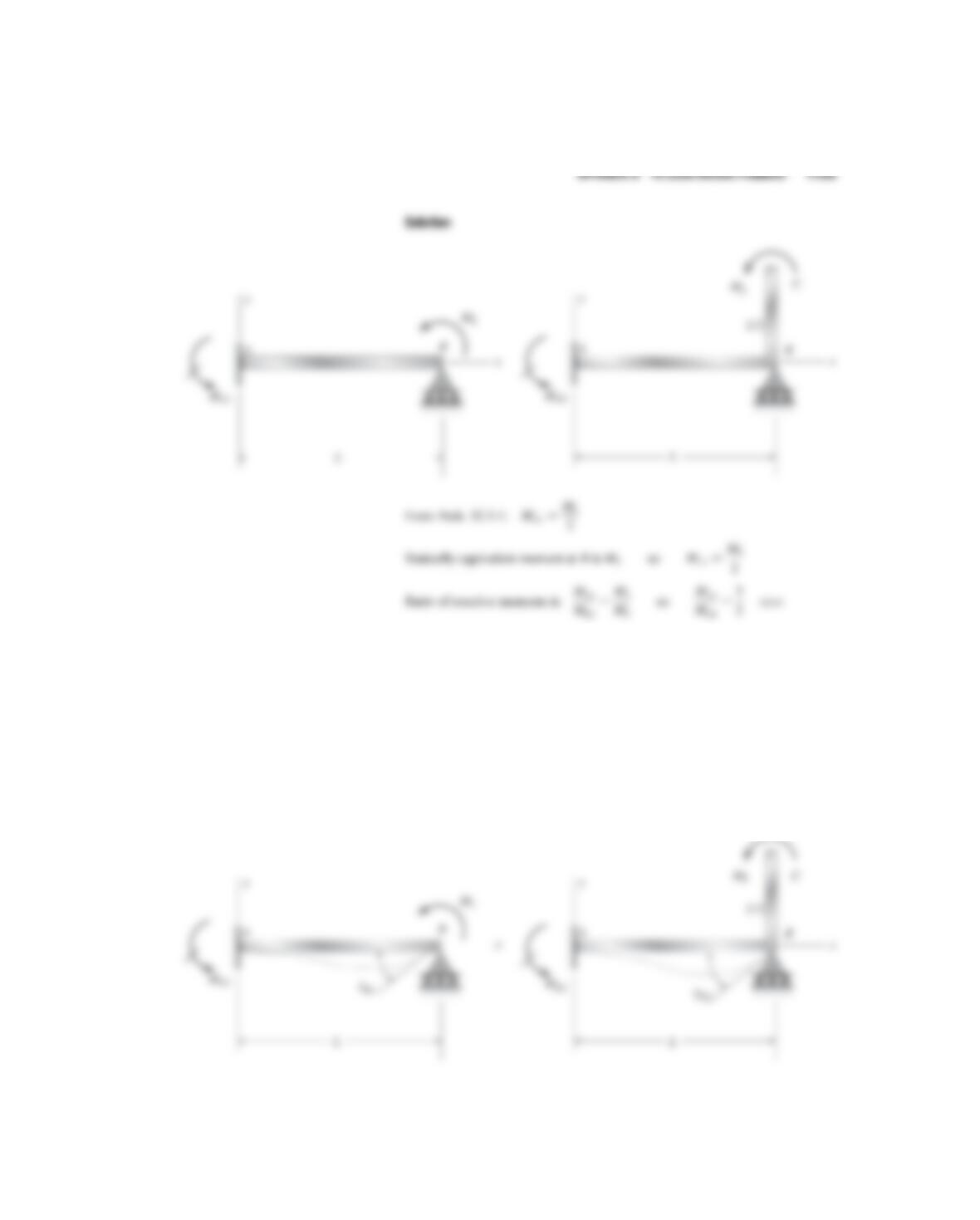
A-10.1: Propped cantilever beam AB has moment M
1
applied at joint B. Framework
ABC has moment M
2
applied at C. Both structures have constant flexural rigidity EI.
If the ratio of the applied moments , the ratio of the reactive moments
at clamped support Ais:
(A) 1
(B) 3/2
(C) 2
(D) 5/2
M
A1
/M
A2
M
1
/M
2
3/2
1154 APPENDIX A FE Exam Review Problems
78572_app_ptg01_hr_1083-1168.qxd 1/24/12 12:15 PM Page 1154
APPENDIX A FE Exam Review Problems 1155
A-10.2: Propped cantilever beam AB has moment M
1
applied at joint B. Framework
ABC has moment M
2
applied at C. Both structures have constant flexural rigidity EI.
If the ratio of the applied moments , the ratio of the joint rotations at
B, , is:
(A) 1
(B) 3/2
(C) 2
(D) 5/2
Solution
u
B1
/u
B2
M
1
/M
2
3/2
Solution
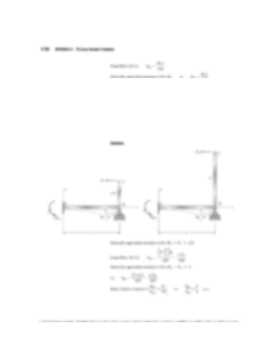
A-10.3: Structure 1 with member BC of length L/2 has force P
1
applied at joint C.
Structure 2 with member BC of length Lhas force P
2
applied at C. Both structures
have constant flexural rigidity EI. If the ratio of the applied forces , the
ratio of the joint B rotations is:
(A) 1
(B) 5/4
(C) 3/2
(D) 2
Solution
u
B1
/u
B2
P
1
/P
2
5/2
1156 APPENDIX A FE Exam Review Problems
78572_app_ptg01_hr_1083-1168.qxd 1/24/12 12:15 PM Page 1156
APPENDIX A FE Exam Review Problems 1157
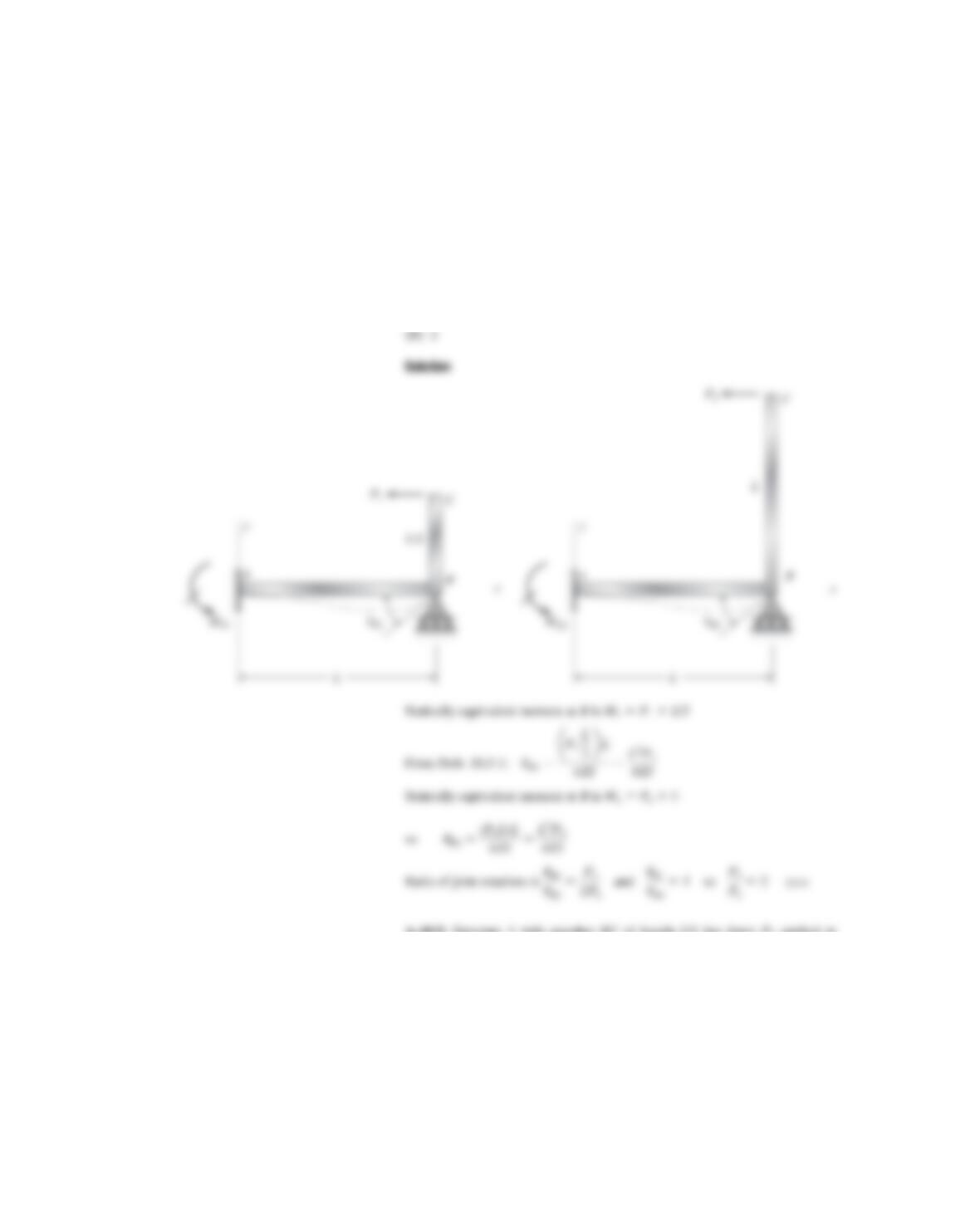
A-10.4: Structure 1 with member BC of length L/2 has force P
1
applied at
joint C. Structure 2 with member BC of length Lhas force P
2
applied at C. Both
structures have constant flexural rigidity EI. The required ratio of the applied
forces so that joint B rotations u
B1
and u
B2
are equal is approximately:
(A) 1
(B) 5/4
(C) 3/2
(D) 2
Solution
P
1
/P
2
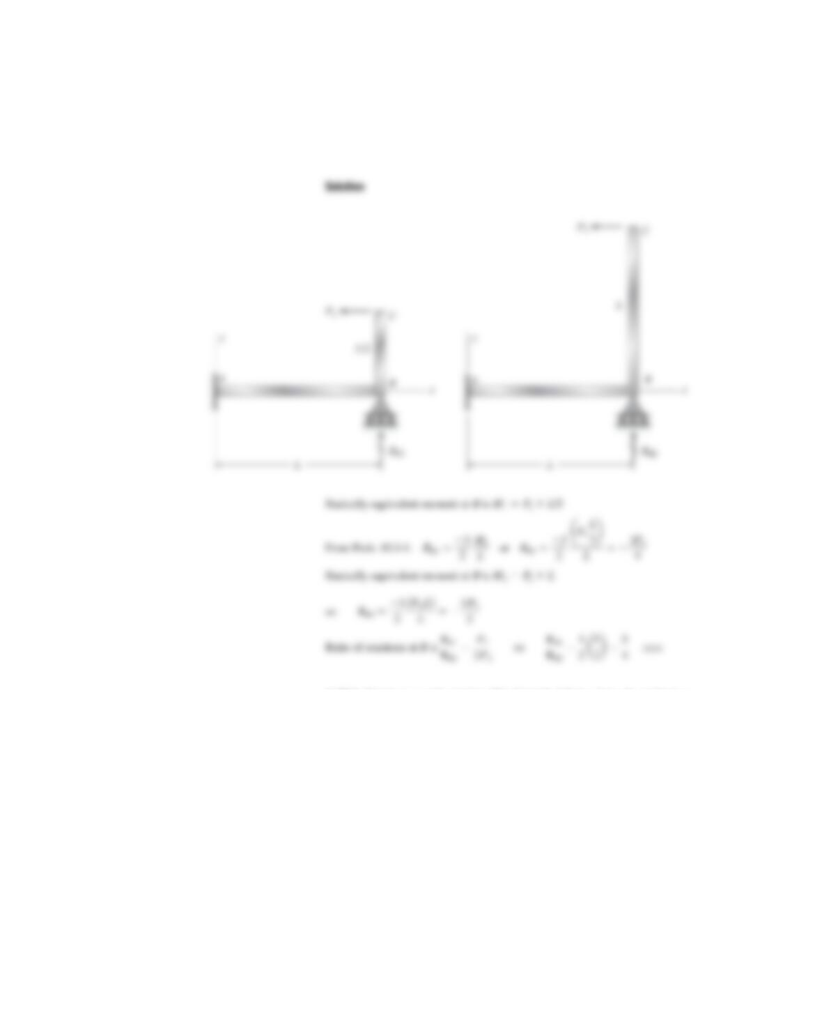
A-10.5: Structure 1 with member BC of length L/2 has force P
1
applied at
joint C. Structure 2 with member BC of length Lhas force P
2
applied at C. Both
structures have constant flexural rigidity EI. If the ratio of the applied forces
, the ratio of the joint B reactions is:
(A) 1
(B) 5/4
(C) 3/2
(D) 2
R
B1
/R
B2
P
1
/P
2
5/2
1158 APPENDIX A FE Exam Review Problems
Solution
A-10.6: Structure 1 with member BC of length L/2 has force P
1
applied at
joint C. Structure 2 with member BC of length Lhas force P
2
applied at C. Both
structures have constant flexural rigidity EI. The required ratio of the applied
forces so that joint B reactions R
B1
and R
B2
are equal is:
(A) 1
(B) 5/4
(C) 3/2
(D) 2
P
1
/P
2
78572_app_ptg01_hr_1083-1168.qxd 1/24/12 12:15 PM Page 1158
APPENDIX A FE Exam Review Problems 1159
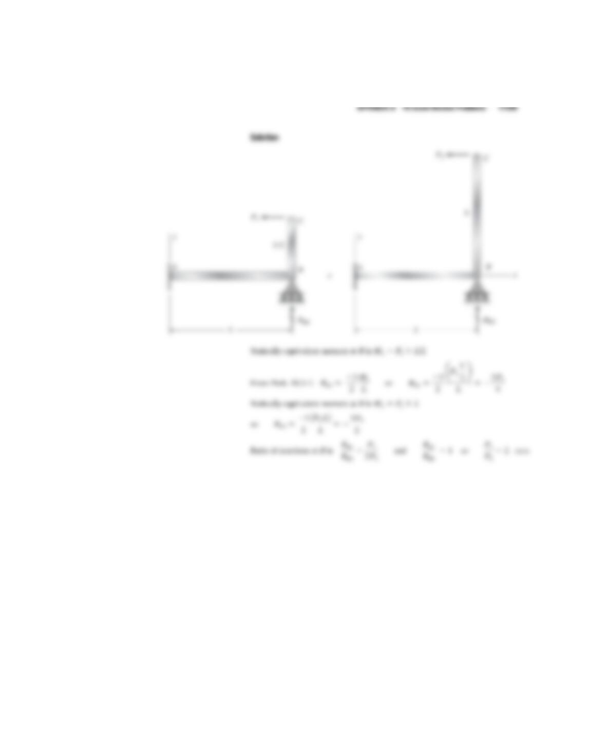
A-10.7: Structure 1 with member BC of length L/2 has force P
1
applied at
joint C. Structure 2 with member BC of length Lhas force P
2
applied at C. Both
structures have constant flexural rigidity EI. If the ratio of the applied forces
, the ratio of the joint C lateral deflections is approximately:
(A) 1/2
(B) 4/5
(C) 3/2
(D) 2
d
C1
/d
C2
P
1
/P
2
5/2
Solution
1160 APPENDIX A FE Exam Review Problems
Solution
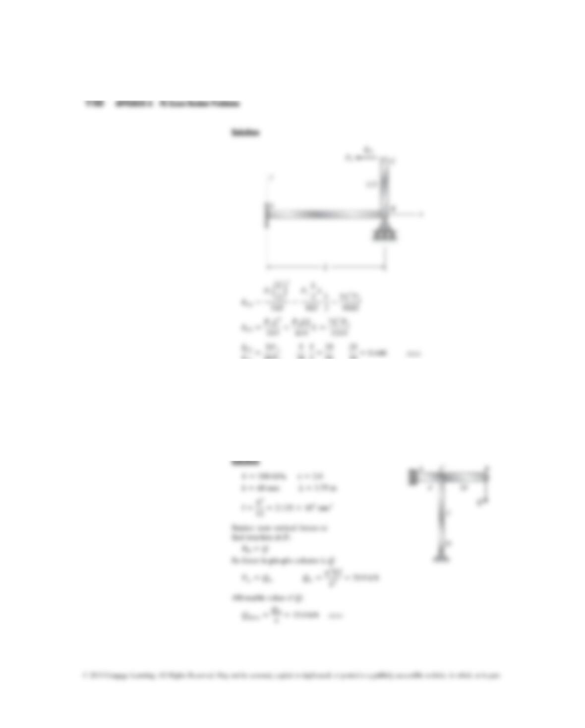
A-11.1: Beam ACB has a sliding support at Aand is supported at Cby a pinned end
steel column with square cross section (E200 GPa, b40 mm) and height
L3.75 m. The column must resist a load Qat Bwith a factor of safety 2.0 with
respect to the critical load. The maximum permissible value of Qis approximately:
(A) 10.5 kN
(B) 11.8 kN
(C) 13.2 kN
(D) 15.0 kN
78572_app_ptg01_hr_1083-1168.qxd 1/24/12 12:15 PM Page 1160
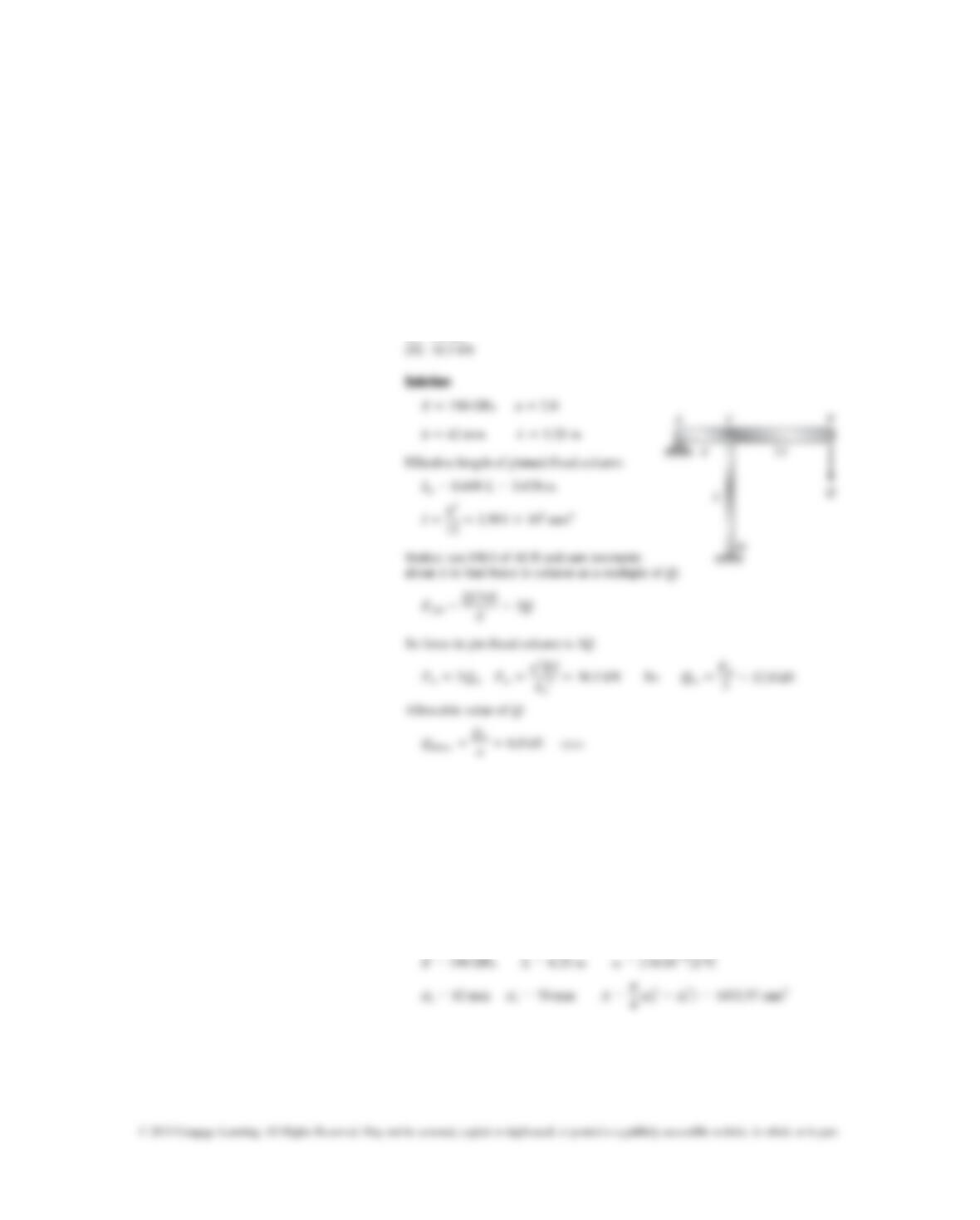
A-11.2: Beam ACB has a pin support at Aand is supported at Cby a steel column
with square cross section (E190 GPa, b42 mm) and height L 5.25 m.
The column is pinned at Cand fixed at D. The column must resist a load Q at
Bwith a factor of safety 2.0 with respect to the critical load. The maximum per-
missible value of Qis approximately:
(A) 3.0 kN
(B) 6.0 kN
(C) 9.4 kN
(D) 10.1 kN
Solution
A-11.3: A steel pipe column (E190 GPa, a 14 10
26
per degree Celsius,
d
2
82 mm, d
1
70 mm) of length L4.25 m is subjected to a temperature
increase T. The column is pinned at the top and fixed at the bottom. The tem-
perature increase at which the column will buckle is approximately:
(A) 36 °C
(B) 42 °C
(C) 54 °C
(D) 58 °C
APPENDIX A FE Exam Review Problems 1161
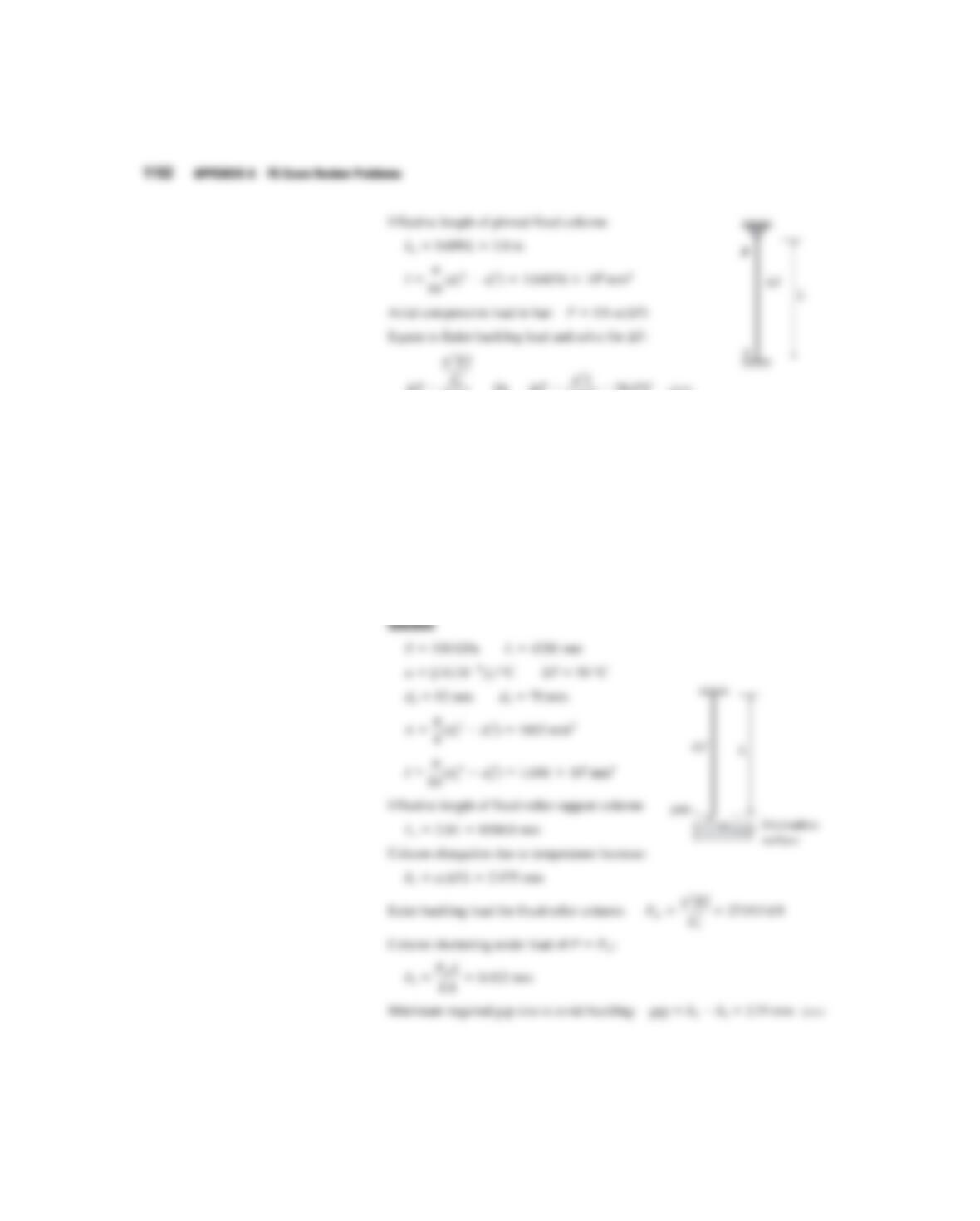
A-11.4: A steel pipe (E190 GPa, , d
2
82 mm, d
1
70 mm)
of length L4.25 m hangs from a rigid surface and is subjected
to a temperature increase T50 °C. The column is fixed at the top and has a
small gap at the bottom. To avoid buckling, the minimum clearance at the bottom
should be approximately:
(A) 2.55 mm
(B) 3.24 mm
(C) 4.17 mm
(D) 5.23 mm
Solution
a14 10
6
/ C
1162 APPENDIX A FE Exam Review Problems
78572_app_ptg01_hr_1083-1168.qxd 1/24/12 12:15 PM Page 1162
A-11.5: A pinned-end copper strut (E 110 GPa) with length L 1.6 m is con-
structed of circular tubing with outside diameter d 38 mm. The strut must
resist an axial load P 14 kN with a factor of safety 2.0 with respect to the crit-
ical load. The required thickness tof the tube is:
(A) 2.75 mm
(B) 3.15 mm
(C) 3.89 mm
(D) 4.33 mm
Solution
A-11.6: A plane truss composed of two steel pipes (E210 GPa, d100 mm,
wall thickness 6.5 mm) is subjected to vertical load Wat joint B. Joints Aand
Care L7 m apart. The critical value of load Wfor buckling in the plane of the
truss is nearly:
(A) 138 kN
(B) 146 kN
(C) 153 kN
(D) 164 kN
APPENDIX A FE Exam Review Problems 1163
A-11.7: A beam is pin-connected to the tops of two identical pipe columns, each
of height h, in a frame. The frame is restrained against sidesway at the top of
column 1. Only buckling of columns 1 and 2 in the plane of the frame is of
interest here. The ratio (a/L) defining the placement of load Q
cr
, which causes
both columns to buckle simultaneously, is approximately:
(A) 0.25
(B) 0.33
(C) 0.67
(D) 0.75
1164 APPENDIX A FE Exam Review Problems
78572_app_ptg01_hr_1083-1168.qxd 1/24/12 12:15 PM Page 1164
A-11.8: A steel pipe column (E 210 GPa) with length L 4.25 m is
constructed of circular tubing with outside diameter d
2
90 mm and inner
diameter d
1
64 mm. The pipe column is fixed at the base and pinned at the
top and may buckle in any direction. The Euler buckling load of the column
is most nearly:
(A) 303 kN
(B) 560 kN
(C) 690 kN
(D) 720 kN
APPENDIX A FE Exam Review Problems 1165
A-11.9: An aluminum tube (E72 GPa) AB of circular cross section has a
pinned support at the base and is pin-connected at the top to a horizontal beam
supporting a load Q600 kN. The outside diameter of the tube is 200 mm and
the desired factor of safety with respect to Euler buckling is 3.0. The required
thickness tof the tube is most nearly:
(A) 8 mm
(B) 10 mm
(C) 12 mm
(D) 14 mm
A-11.10: Two pipe columns are required to have the same Euler buckling load
P
cr
. Column 1 has flexural rigidity E I and height L
1
; column 2 has flexural
rigidity (4/3)E I and height L
2
. The ratio (L
2
/L
1
) at which both columns will
buckle under the same load is approximately:
(A) 0.55
(B) 0.72
(C) 0.81
(D) 1.10
1166 APPENDIX A FE Exam Review Problems
78572_app_ptg01_hr_1083-1168.qxd 1/24/12 12:15 PM Page 1166
Solution
A-11.11: Two pipe columns are required to have the same Euler buckling load
P
cr
. Column 1 has flexural rigidity E I
1
and height L; column 2 has flexural
rigidity (2/3)E I
2
and height L. The ratio (I
2
/I
1
) at which both columns will
buckle under the same load is approximately:
(A) 0.8
(B) 1.0
(C) 2.2
(D) 3.1
Solution
APPENDIX A FE Exam Review Problems 1167