Solutions — Chapter 6
6.1.1. (a)K= 3−2
−2 3 !; (b)u=0
@
18
5
17
51
A= 3.6
3.4!; (c) the first mass has moved the
farthest; (d)e=“18
5,−1
5,−17
5”T= ( 3.6,−.2,−3.4 )T, so the first spring has stretched
the most, while the third spring experiences the most compression.
6.1.3. 6.1.1: (a)K= 3−2
−2 2 !; (b)u= 7
17
2!= 7.0
8.5!; (c) the second mass has
moved the farthest; (d)e=“7,3
2”T= ( 7.0,1.5 )T, so the first spring has stretched the
most.
2,3”T= ( 3.5,3.)T, so the first spring has stretched slightly farther.
6.1.4.
(a)u= ( 1,3,3,1 )T,e= ( 1,2,0,−2,−1 )T. The solution is unique since Kis invertible.
(b) Now u= ( 2,6,7.5,7.5 )T,e= ( 2,4,1.5,0 )T. The masses have all moved farther, and
the springs are elongated more; in this case, no springs are compressed.
6.1.5.
(a) Since e1=u1,ej=uj−uj+1, for 2 ≤j≤n, while en+1 =−un, so
e1+···+en+1 =u1+ (u2−u1)+(u2−u1)+···+ (un−un−1)−un= 0.
Alternatively, note that z= ( 1,1,…,1 )T∈coker Aand hence z·e=e1+···+en+1 = 0

♣6.1.7. Top and bottom support; constant force:
20 40 60 80 100
2
4
6
8
10
12
20 40 60 80 100
-0.4
-0.2
0.2
0.4
Top and bottom support; linear force:
20 40 60 80 100
10
20
30
40
50
20 40 60 80 100
0.2
0.4
0.6
0.8
1
Top support only; linear force:
160
6.1.8.
(a) For maximum displacement of the bottom mass, the springs should be arranged from
weakest at the top to strongest at the bottom, so c1=c= 1, c2=c0= 2, c3=c00 = 3.
(b) In this case, the order giving maximum displacement of the bottom mass is c1=c= 2,
c2=c0= 3, c3=c00 = 1.
♣6.1.9.
(a) When the bottom end is free, for maximum displacement of the bottom mass, the springs
6.1.10.
The sub-diagonal entries of Lare li,i−1=−1
i, while the diagonal entries of Dare dii =i+ 1
i.
♥6.1.11.
(a) Since y=Au, we have y∈rng A= corng AT. Thus, according to Theorem 5.59, yhas
minimal Euclidean norm among all solutions to ATy=f.
6.1.12. Regular Gaussian Elimination reduces them to 0
B
@
2−1 0
03
21
0 0 4
3
1
C
A,0
B
@
2−1 0
03
21
0 0 1
3
1
C
A, respec-
tively. Since all three pivots are positive, the matrices are positive definite.
161
6.1.14.
(a)p(u) = 1
2(u1u2) 3−2
−2 3 ! u1
u2!−(u1u2) 4
3!
=3
2u2
1−2u1u2+3
2u2
2−4u1−3u2,so p(u?) = p“3.6,3.4”=−12.3.
(b) For instance, p(1,0) = −2.5, p(0,1) = −1.5, p(3,3) = −12.
6.1.16.
(a) Two masses, both ends fixed, c1= 2, c2= 4, c3= 2, f= ( −1,3 )T;
equilibrium: u?= ( .3, .7 )T.
6.1.17. In both cases, the homogeneous system Au=0requires 0 = u1=u2=··· =un, and so
ker A={0}, proving linear independence of its columns.
6.1.18. This is an immediate consequence of Exercise 4.2.9.
♥6.1.19.
(a) When only the top end is supported, the potential energy is lowest when the springs are
6.1.20. True. The potential energy function (6.16) uniquely determines the symmetric stiffness
matrix Kand the external force vector f. According to (6.12), (6.15), the off-diagonal en-
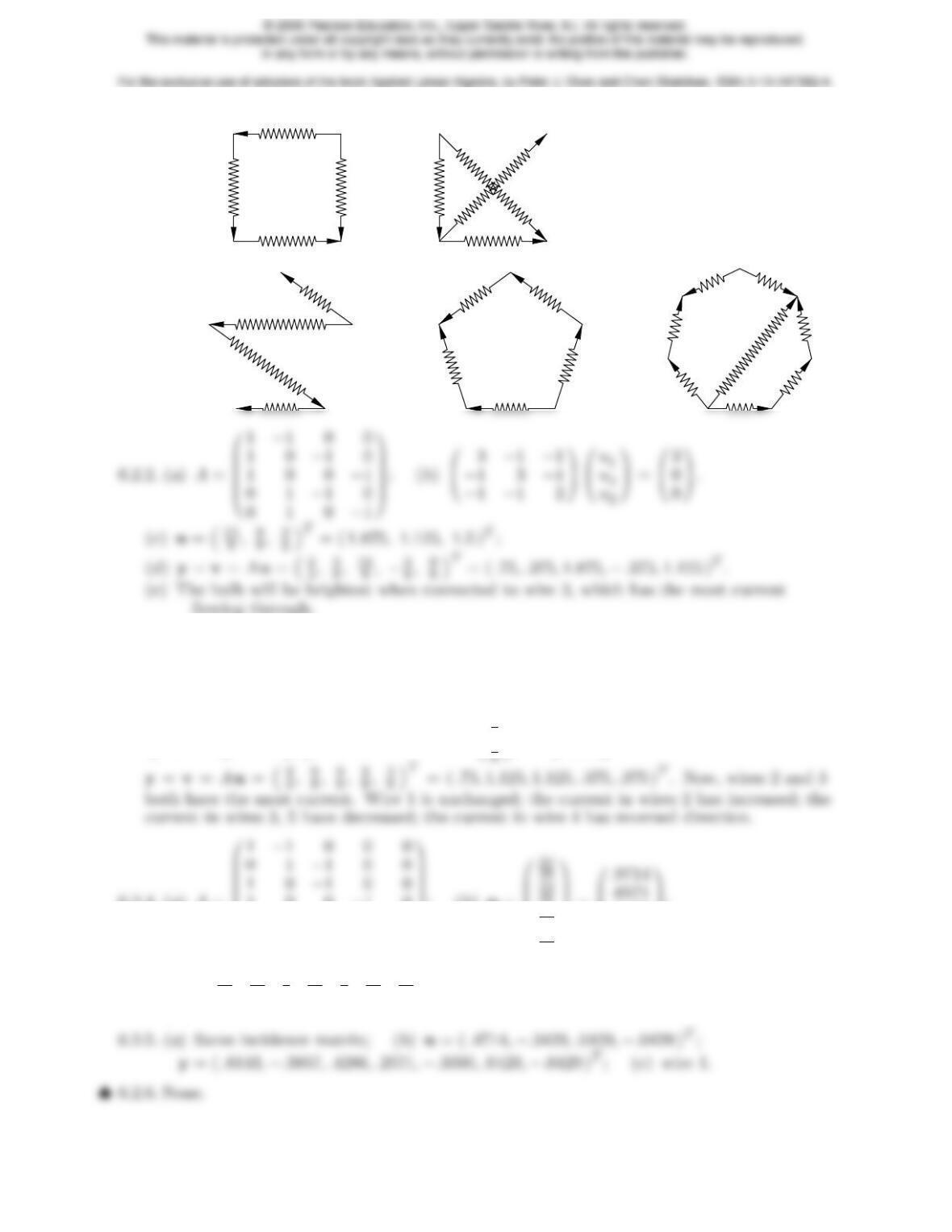
6.2.1. (a) (b)
(c) (d) (e)
flowing through.
6.2.3. The reduced incidence matrix is A?=0
B
B
B
B
B
@
1−1
1 0
1 0
0 1
0 1
1
C
C
C
C
C
A
, and the equilibrium equations are
3−1
−1 3 !u= 3
0!, with solution u=0
@
9
8
3
A= 1.125
.375 !; the resulting currents are
6.2.4. (a)A=
B
B
B
B
B
@
100−1 0
010−1 0
0 0 1 0 −1
0 0 0 1 −1
C
C
C
C
C
A
; (b)u=0
B
B
@
35
19
35
16
35
C
C
A
=0
B
@
.5429
.4571
C
A;
y=“11
35 ,4
35 ,3
7,9
35 ,1
5,19
35 ,16
35 ”T= ( .3143, .1143, .4286, .2571, .2000, .5429, .4571 )T;
(c) wire 6.
163
♠6.2.7. There is no current on the two wires connecting the same poles of the batteries (positive-
positive and negative-negative) and 2.5 amps along all the other wires.
♠6.2.8.
(a) The potentials remain the same, but the currents are all twice as large.
♣6.2.10.
(a) For n= 2, the potentials are
0
B
B
B
@
1
16
1
8
1
16
1
8
3
8
1
8
1
1
1
1
C
C
C
A=0
B
@
.0625 .125 .0625
.125 .375 .125
.0625 .125 .0625 1
C
A.
where all wires are oriented from left to right, so the currents are all going away from
the center. The currents in the vertical wires are given by the transpose of the matrix.
For n= 4, the potentials are
0
B
B
B
B
.0165 .0331 .0478 .0551 .0478 .0331 .0165
.0331 .0680 .1029 .125 .1029 .0680 .0331
.0478 .1029 .1710 .2390 .1710 .1029 .0478
1
C
C
C
C
164
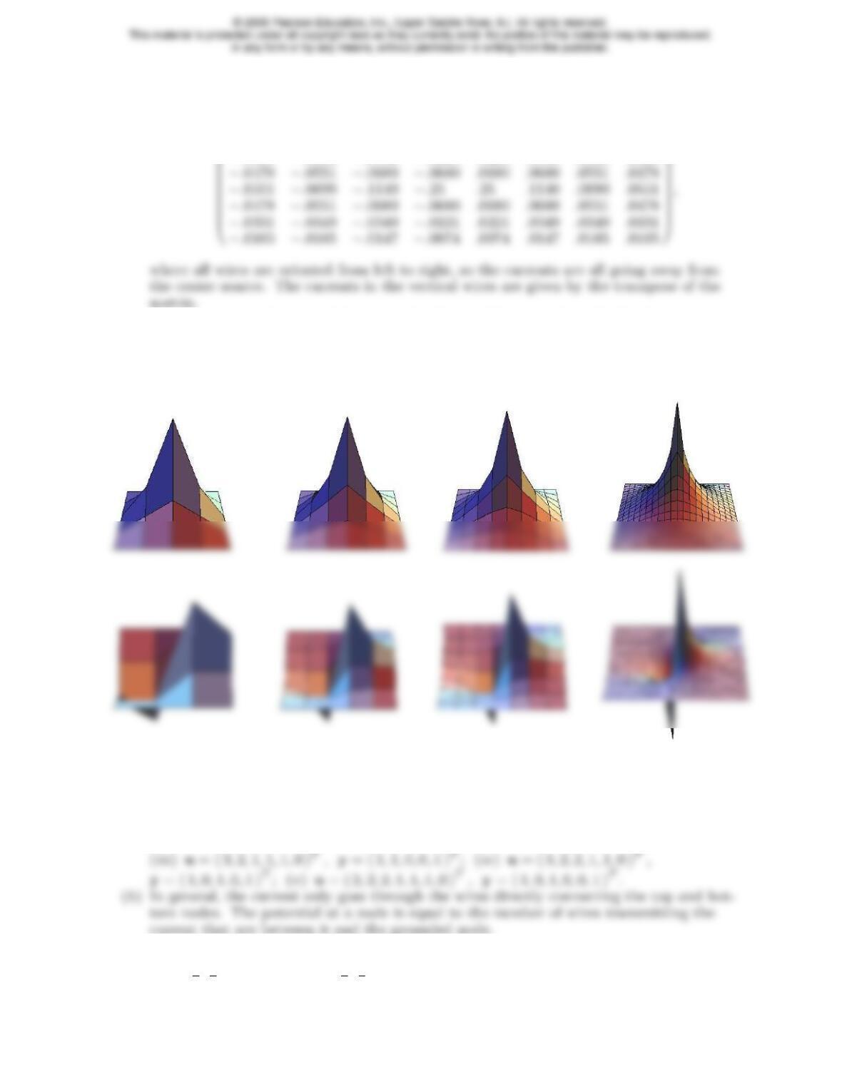
The currents along the horizontal wires are
0
B
B
−.0165 −.0165 −.0147 −.0074 .0074 .0147 .0165 .0165
−.0331 −.0349 −.0349 −.0221 .0221 .0349 .0349 .0331
1
C
C
As n→ ∞ the potentials approach a limit, which is, in fact, the fundamental so-
lution to the Dirichlet boundary value problem for Laplace’s equation on the square,
[47,59]. The horizontal and vertical currents tend to the gradient of the fundamental
solution. But this, of course, is the result of a more advanced analysis beyond the scope
of this text. Here are graphs of the potentials and horizontal currents for n= 2,3,4,10:
6.2.11. This is an immediate consequence of Theorem 5.59, which states that the minimum
norm solution to ATy=fis characterized by the condition y= corng AT= rng A. But,
solving the system ATAu=fresults in y=Au∈rng A.
6.2.12.
(a) (i)u= ( 2,1,1,0 )T,y= ( 1,0,1 )T; (ii )u= ( 3,2,1,1,0 )T,y= ( 1,1,0,1 )T;
6.2.13.
(i)u=“3
2,1
2,0,0”T,y=“1,1
2,1
2”T;
165
For the exclusive use of adopters of the book Applied Linear Algebra, by Peter J. Olver and Cheri Shakiban. ISBN 0-13-147382-4.
6.2.14. According to Exercise 2.6.8(b), a tree with nnodes has n−1 edges. Thus, the reduced
incidence matrix A?is square, of size (n−1) ×(n−1), and is nonsingular since the tree is
connected.
6.2.15.
6.2.16. In general, if v1, . . . , vmare the rows of the (reduced) incidence matrix A, then the re-
sistivity matrix is K=ATC A =
m
X
civT
6.2.17.
(a) If fare the current sources at the nodes and bthe battery terms, then the nodal volt-
age potentials satisfy ATC Au=f−ATCb.
(b) By linearity, the combined potentials (currents) are obtained by adding the potentials
(currents) due to the batteries and those resulting from the current sources.
♦6.2.18. The resistivity matrix K?is symmetric, and so is its inverse. The (i, j) entry of (K?)−1
is the ith entry of uj= (K?)−1ej, which is the potential at the ith node due to a unit cur-
6.2.19. If the graph has kconnected subgraphs, then there are kindependent compatibility
6.3.2. The bar will be stress-free provided the vertical force is 1.5 times the horizontal force.
6.3.3.
(a) For a unit horizontal force on the two nodes, the displacement vector is
6.3.4. The swing set cannot support a uniform horizontal force, since f1=f2=f,
g1=g2=h1=h2= 0 does not satisfy the constraint for equilibrium. Thus, the swing
set will collapse. For the reinforced version, under a horizontal force of magnitude f, the
displacements of the two free nodes are ( 14.5f, 0,−3f)Tand ( 14.5f, 0,3f)Trespectively,
♥6.3.5. (a)A=
0
B
B
B
B
B
B
B
@
0100
−1010
0001
0 0 1
√2
1
√2
−1
√2
1
√20 0
1
C
C
C
C
C
C
C
A
; (b)
3
2u1−1
2v1−u2= 0,
−1
2u1+3
2v1= 0,
−u1+3
2u2+1
2v2= 0,
1
2u2+3
2v2= 0.
(c) Stable, statically indeterminate. (d) Write down f=Ke1, so f1= 3
2
0!.
Joined version:
u= ( .0909, .8182,−.0909, .8182,0, .3636 )T,
e= ( .8182,−.1818, .8182, .2571, .2571, .2571, .2571 )T;
Thus, joining the nodes causes a larger vertical displacement, but smaller horizontal dis-
6.3.7.
B
B
B
0 1 0 0 0 0
−1
√2−1
√2
1
√2
1
√20 0
1
C
C
C
♥6.3.8.
(a)A=
0
B
B
B
B
B
B
0 1 0 0 0 0
−3
√10 −1
√10
3
√10
1
√10 0 0
−1 0 0 0 1 0
1
C
C
C
C
C
C
0 0 0 0 0 1
(b) One instability: the mechanism of simultaneous horizontal motion of the three nodes.
(c) No net horizontal force: f1+f2+f3= 0. For example, if f1=f2=f3= ( 0,1 )T, then
e=„3
2,q5
2,−3
2,q5
2,3
2«T
= ( 1.5,1.5811,−1.5,1.5811,1.5 )T, so the compressed di-
agonal bars have slightly more stress than the compressed vertical bars or the elongated
♣6.3.9. Two-dimensional house:
0
B
B
B
B
B
B
0 1 0 0 0 0 0 0 0 0
0−1 0 1 0 0 0 0 0 0
−1 0 0 0 0 0 0 0 1 0
1
C
C
C
C
C
C
(c) Numbering the five movable nodes in order starting at the middle left, the correspond-
ing forces f1= ( f1, g1)T,…,f5= ( f5, g5)Tmust satisfy: f1+f5= 0, f2+f3+
f4= 0, f2+1
2f3+g3= 0. When f1=f2=f4=f5= ( 0,1 )T,f3=0,
(d) To stabilize the structure, you need to add in at least three more bars.
(e) Suppose we add in an upper horizontal bar and two diagonal bars going from lower left
Three-dimensional house:
(a)
0
B
B
B
B
B
B
B
B
B
B
B
B
0 0 1 0 0 0 0 0 0
0−1
√2−1
√201
√2
1
√20 0 0
0−1 0 0 0 0 0 1 0
0 0 0 0 −1
√2
1
√201
√2−1
√2
0 0 0 0 0 0 0 0 1
−1 0 0 0 0 0 0 0 0
(b) 5 mechanisms: horizontal motion of (i) the two topmost nodes in the direction of the
bar connecting them; (ii ) the two right side nodes in the direction of the bar connect-
ing them; (iii ) the two left side nodes in the direction of the bar connecting them;
169
(e) To stabilize, you need to add in at least five more bars, e.g., two diagonal bars across
the front and back walls and a bar from a fixed node to the opposite topmost node.
In all cases, if a minimal number of reinforcing bars are added, the stresses remain
the same on the old bars, while the reinforcing bars experience no stress. See Exercise
6.3.21 for the general result.
♥6.3.10.
(a) Letting widenote the vertical displacement and hithe vertical component of the force
on the ith mass, 2w1−w2=h1,−w1+ 2w2−w3=h2,−w2+w3=h3.The system is
statically determinate and stable.
♥6.3.11.
(a) The incidence matrix is
A=
0
B
B
B
B
B
B
B
B
B
@
1−1
−1 1
−1 1
−1 1
......
1
C
C
C
C
C
C
C
C
C
A
170
the ring is zero.
(c) For instance, if c1=c2=c3=c4= 1, and f= ( 1,−1,0,0 )T, then the solution is
u=“1
4,−1
2,−1
4,0”T+t( 1,1,1,1 )Tfor any t. Nonuniqueness is telling us that the
masses can all be moved by the same amount, i.e., the entire ring is rotated, without
affecting the force balance at equilibrium.
♣6.3.12.
(a)
(c)v1,v2,v3correspond to translations in, respectively, the x, y, z directions;
(d)v4,v5,v6correspond to rotations around, respectively, the x, y, z coordinate axes;
0
B
B
B
B
B
B
B
B
B
B
1 0 0 −100000000
0 1 0 0 0 0 0 −1 0 0 0 0
00100000000−1
−1 0 0 2 −1
2−1
2−1
2
1
20−1
201
2
0 0 0 −1
1
1
C
C
C
C
C
C
C
C
C
C
171
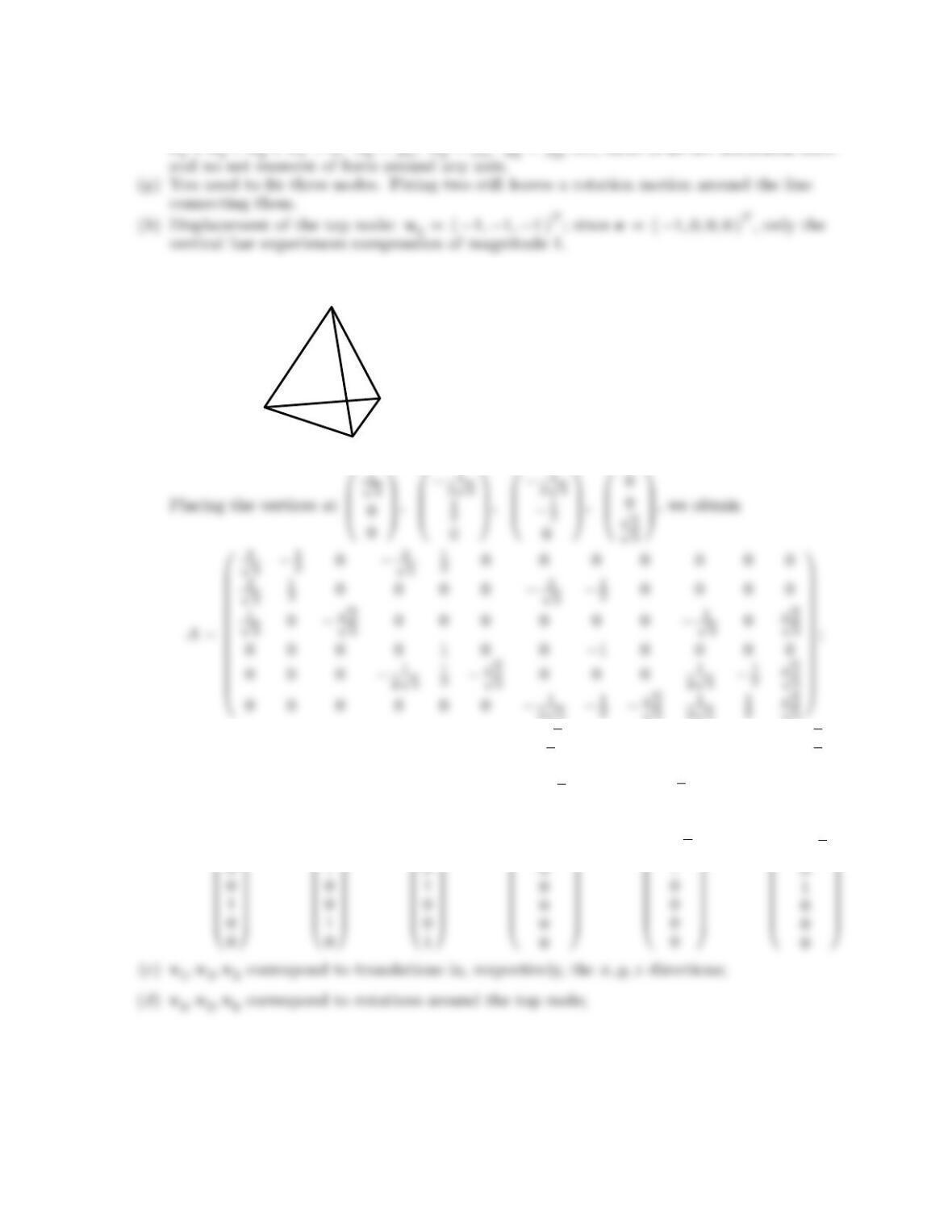
(f) For fi= ( fi, gi, hi)Twe require f1+f2+f3+f4= 0, g1+g2+g3+g4= 0,
♣6.3.13.
(a)
1
1
1
1
2√3−1
2√3
(b)v1=
0
B
B
B
B
B
B
B
B
B
B
B
B
B
B
B
1
0
0
1
0
0
1
1
C
C
C
C
C
C
C
C
C
C
C
C
C
C
C
,v2=
0
B
B
B
B
B
B
B
B
B
B
B
B
B
B
B
0
1
0
0
1
0
0
1
C
C
C
C
C
C
C
C
C
C
C
C
C
C
C
,v3=
0
B
B
B
B
B
B
B
B
B
B
B
B
B
B
B
0
0
1
0
0
1
0
1
C
C
C
C
C
C
C
C
C
C
C
C
C
C
C
,v4=
0
B
B
B
B
B
B
B
B
B
B
B
B
B
B
B
−√2
√6
−1
−2√2
0
1
0
1
C
C
C
C
C
C
C
C
C
C
C
C
C
C
C
,v5=
0
B
B
B
B
B
B
B
B
B
B
B
B
B
B
B
0
−2
0
√3
1
0
−√3
1
C
C
C
C
C
C
C
C
C
C
C
C
C
C
C
,v6=
0
B
B
B
B
B
B
B
B
B
B
B
B
B
B
B
−√2
−√6
−1
0
0
0
−2√2
1
C
C
C
C
C
C
C
C
C
C
C
C
C
C
C
;
172
© 2006 Pearson Education, Inc., Upper Saddle River, NJ. All rights reserved.
This material is protected under all copyright laws as they currently exist. No portion of this material may be reproduced,
in any form or by any means, without permission in writing from the publisher.
For the exclusive use of adopters of the book Applied Linear Algebra, by Peter J. Olver and Cheri Shakiban. ISBN 0-13-147382-4.
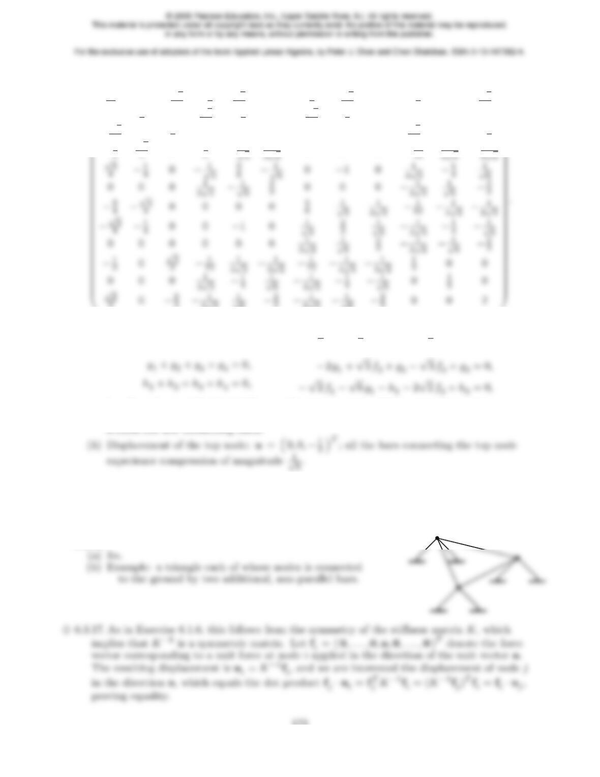
(e)K=
0
B
B
B
B
B
B
B
B
B
B
B
11
60−√2
3−3
4
√3
40−3
4−√3
40−1
30√2
3
01
20√3
4−1
40−√3
4−1
40 0 0 0
−√2
302
30 0 0 0 0 0 √2
30−2
3
−3
4
√3
405
6−1
√3
1
12
1
30−2
3−1
3√2
3−1
3√2−1
3002
1
C
C
C
C
C
C
C
C
C
C
C
(f) For fi= ( fi, gi, hi)Twe require
f1+f2+f3+f4= 0,
−√2f1+√6g1−h1−2√2f2+h2= 0,
i.e., there is no net horizontal force and no net moment of force around any axis.
(g) You need to fix three nodes. Fixing only two nodes still permits a rotational motion
6.3.14. True, since stability only depends on whether the reduced incidence matrix has trivial
kernel or not, which depends only on the geometry, not on the bar stiffnesses.
6.3.15. (a) True. Since Ku=f, if f6=0then u6=0also. (b) False if the structure is unsta-
ble, since any u∈ker Ayields a zero elongation vector y=Au=0.
6.3.16.
173
6.3.19. Since y=e=Au∈rng A= corng AT, which, according to Theorem 5.59, is the
condition for the solution of minimal norm to the adjoint equation.
♦6.3.20.
(a) We are assuming that f∈rng K= corng A= rng AT, cf. Exercise 3.4.31. Thus, we can
write f=ATh=ATCgwhere g=C−1h.
(b) The equilibrium equations Ku=fare ATC Au=ATCgwhich are the normal equa-
tions (4.57) for the weighted least squares solution to Au=g.
♥6.3.21. Let Abe the reduced incidence matrix of the structure, so the equilibrium equations are
ATC Au=f, where we are assuming f∈rng K= rng ATC A. We use Exercise 6.3.20 to
write f=ATCgand characterize uas the weighted least squares solution to Au=g, i.e.,
the vector that minimizes the weighted norm kAu−gk2.
♥6.3.22.
(a)A?=0
B
B
B
B
@
1
√2
1
√20 0 0
−1 0 1 0 0
0 0 −1
√2
1
√2
1
√2
1
C
C
C
C
A;K?u=f?where K?=
0
B
B
B
B
B
B
B
B
@
3
2
1
2−1 0 0
1
2
1
2000
−1 0 3
2−1
2−1
2
0 0 −1
2
1
2
1
2
0 0 −1
2
1
2
1
2
1
C
C
C
C
C
C
C
C
A
.
174
♥6.3.23.
(a)A?=0
B
B
B
B
@
1
√2
1
√20 0 0
−1 0 1 0 0
0 0 −1
√2
1
√2−1
√2
1
C
C
C
C
A;
♥6.3.24.
(a) Horizontal roller: A?=0
B
B
B
B
B
@
.7071 .7071 0 0 0
−1 0 1 0 0
0 0 −.7071 .7071 .7071
−.9487 .3162 0 0 .9487
1
C
C
C
C
C
A
;
0
1
(b) Vertical roller: A?=0
B
B
B
B
B
@
.7071 .7071 0 0 0
−1 0 1 0 0
0 0 −.7071 .7071 −.7071
−.9487 .3162 0 0 −.3162
1
C
C
C
C
C
A
;
6.3.25.
(a) Yes, if the direction of the roller is perpendicular to the vector between the two nodes,
the structure admits an (infinitesimal) rotation around the fixed node.
175
For the exclusive use of adopters of the book Applied Linear Algebra, by Peter J. Olver and Cheri Shakiban. ISBN 0-13-147382-4.