
Case – Hydraulic Lift Co.
The Hydraulic Lift Company (HLC) manufactures freight elevators and automotive lifts
used in garages and service stations. Figure 1 shows a simplified diagram of a hydraulic
lift. The check valve is an important component in the system. Its purpose is to control
the flow of hydraulic oil from the oil reservoir to the cylinder when the elevator is rising.
As the elevator descends, the rate at which oil flows from the cylinder back to the
reservoir is also controlled by the check valve.
One of the most important parts of the check valve is the piston, which moves within
the valve body as the valve is opened or closed. The quality manager at HLC noticed that
scrap rates on the piston had been very high over the past three years. Two models (part
numbers 117227 and 117228) of check valve pistons are being manufactured. Because of
extremely critical tolerances, these parts are among the most difficult ones produced in
the machine shop.
A study to determine the magnitude of the problem revealed that approximately
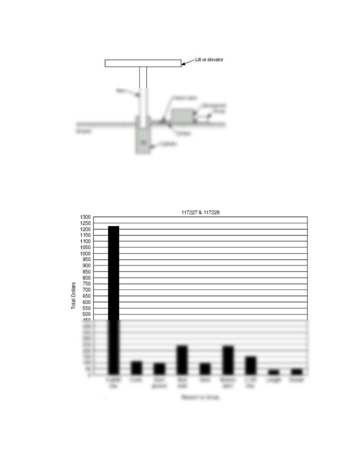
Figure 1 Simplified Diagram of Hydraulic Lift
Figure 2 Average Scrap Cost Per Month
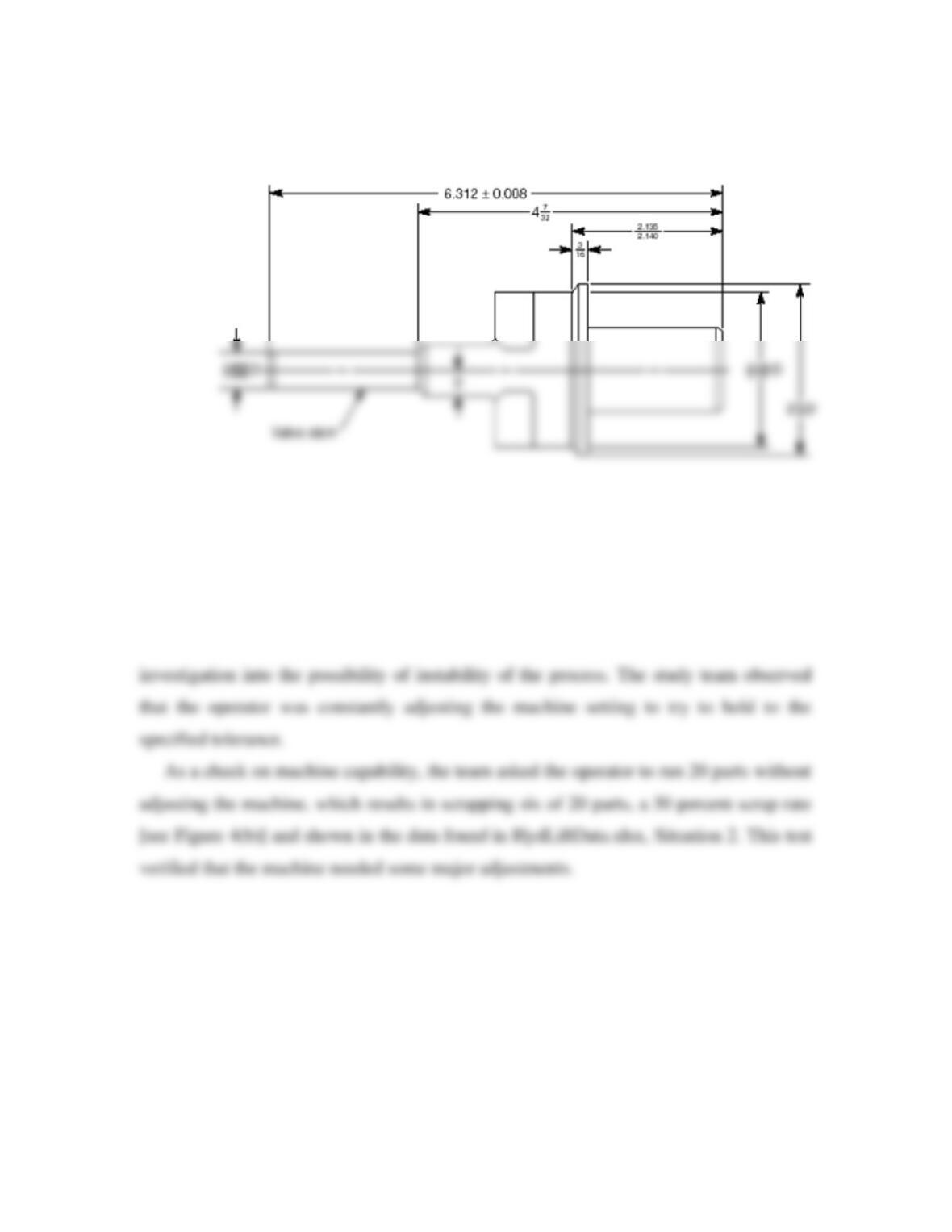
Figure 3 Part No. 117227 Check Valve
For the first step, an operator ran 100 parts using the standard production methods.
Results of the study [see the histogram in Figure 4(a)] and shown in the data found in
HydLiftData.xlsx, Situation 1, revealed that a machine problem existed. The data showed
that a few parts were being produced outside the specifications. In addition, the strange
shape of the histogram for dimensions within the specification limits prompted an
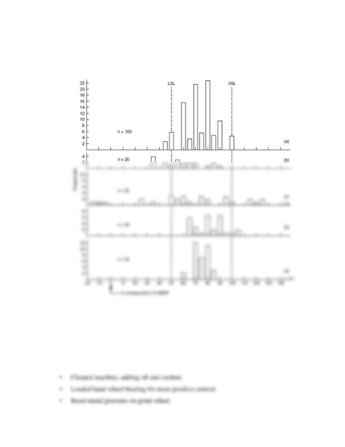
Figure 4 Process Capability for Hydraulic Lift Company
The machine manufacturer was contacted and a technician was dispatched to the
plant. A run of 30 parts was made to show how the machine operated. Twelve of the 30
pieces were defective, with the stem dimension out of tolerance [see Figure 4(c)] and
shown in the data found in HydLiftData.xlsx, Situation 3. The technician made the
following adjustments:
• Installed new gaskets.
• Adjusted stone dresser mechanism.
• Reset dwell time (time the grindstone stays on the workpiece after reaching final
diameter).
The results of these adjustments were significant. Another 30 parts were run, with
only two falling outside the tolerance limits [Figure 4(d)], and shown in the data found in
HydLiftData.xlsx, Situation 4. The team still did not consider the process to be fully
satisfactory. The manufacturer’s technician said that the grinder “ways” (channels on
Assignment
1. Using the histograms in Figure 4 and the data found in HydLiftData.xlsx,
Situation 1 and 5, calculate the process capability indexes for the original and the final
situations. (Note that in Situation 1, the process is probably not in control, so the