Lab Exercise – Ethernet
Objective
To explore the details of Ethernet frames. Ethernet is a popular link layer protocol that is covered in §4.3
of your text; modern computers connect to Ethernet switches (§4.3.4) rather than use classic Ethernet
(§4.3.2). Review section §4.3 before doing this lab.
Requirements
Wireshark: This lab uses the Wireshark software tool to capture and examine a packet trace. A packet
trace is a record of traffic at a location on the network, as if a snapshot was taken of all the bits that
passed across a particular wire. The packet trace records a timestamp for each packet, along with the
bits that make up the packet, from the lower–layer headers to the higher–layer contents. Wireshark runs
on most operating systems, including Windows, Mac and Linux. It provides a graphical UI that shows the
ping: This lab uses “ping” to send and receive messages. ping is a standard command–line utility for
checking that another computer is responsive. It is widely used for network troubleshooting and comes
Step 1: Capture a Trace
Proceed as follows to capture a trace of ping packets; alternatively you may use a supplied trace. We will
use ping simply as an easy way to collect a small trace. Perhaps surprisingly, you can capture a trace for
this lab from a computer connected to the Internet using either wired Ethernet or wireless 802.11.
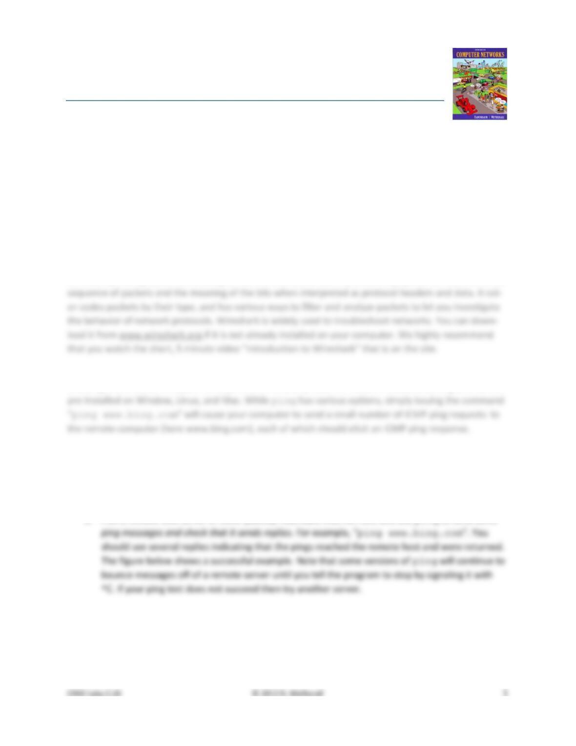
1. Pick a remote web server or other publicly reachable Internet host and use ping to send some
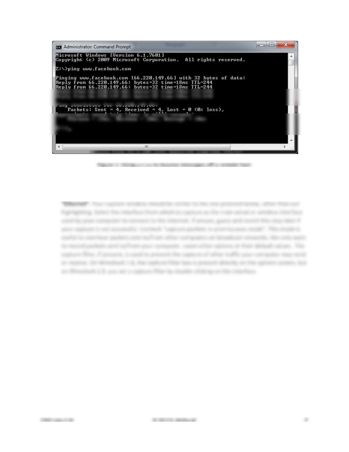
2. Launch Wireshark and start a capture of Ethernet frames with a filter of “icmp”, making sure
that “enable MAC name resolution” is checked. The latter will translate Ethernet (MAC) ad-
dresses to provide vendor information. Also check that the Link–layer header type pulldown says
3. When the capture is started, repeat the ping command above. This time, the packets will also
4. After the ping command is complete, return to Wireshark and use the menus or buttons to stop
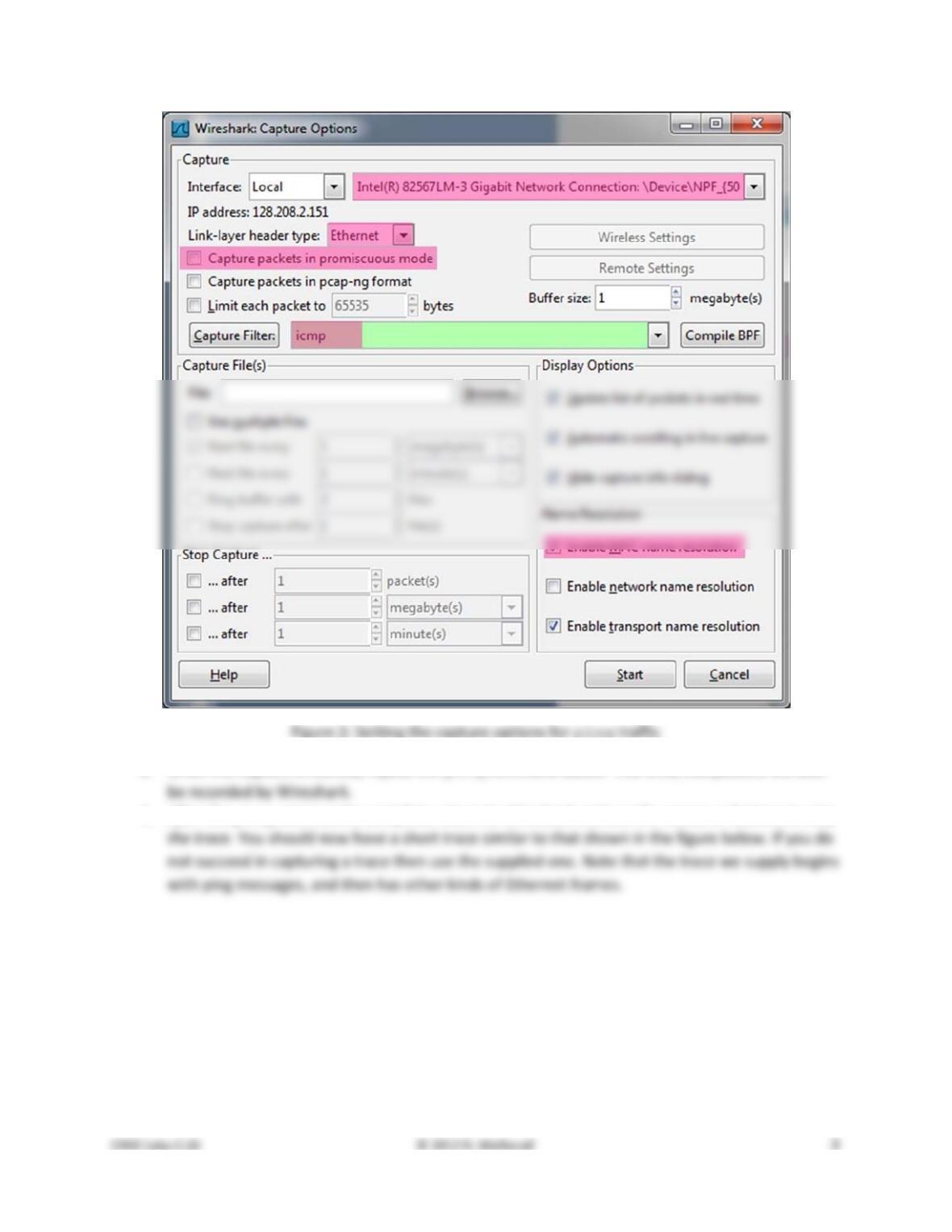
Figure 3: Trace of ping traffic, showing Ethernet details of the first packet
Step 2: Inspect the Trace
Select any packet in the trace (in the top panel) to see details of its structure (in the middle panel) and
the bytes that make up the packet (in the bottom panel). Now we can inspect the details of the packets.
In the figure, we have selected the first packet in the trace. Note that we are using the term “packet” in
Ethernet format on the capture options (in Figure 2). In this case, the OS software converted the real
802.11 header into a pseudo–Ethernet header. We are seeing the pseudo–Ethernet header.
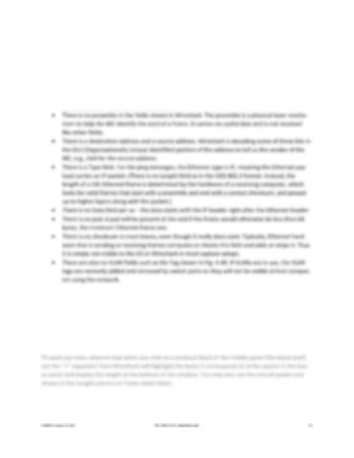
Compare the fields you see with the picture of an Ethernet frame in Fig. 4–14 of your text. You will see
both similarities and differences:
• There are two kinds of Ethernet shown in your book, IEEE 802.3 and DIX Ethernet. IEEE 802.3 is
rare and you are not likely to see it. The frames in the figure and likely your capture are DIX
Ethernet, called “Ethernet II” in Wireshark.
Step 3: Ethernet Frame Structure
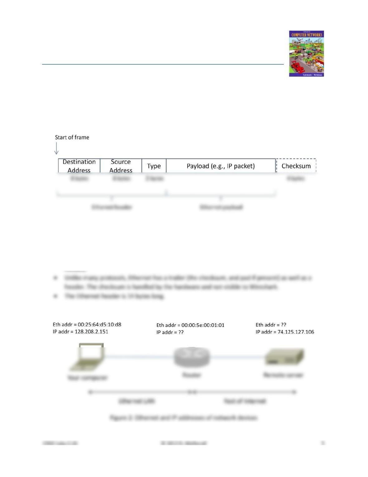
To show your understanding of the Ethernet frame format, draw a figure of the ping message that shows
the position and size in bytes of the Ethernet header fields. Your figure can simply show the frame as a
long, thin rectangle. The leftmost fields come first in the packet and are sent on the wire first. On this
drawing, show the range of the Ethernet header and the Ethernet payload. Add a dashed box at the end
to represent the 4–byte checksum; we know it is there even if Wireshark does not show us this field.
Turn–in: Hand in your drawing of an Ethernet frame.
Step 4: Scope of Ethernet Addresses
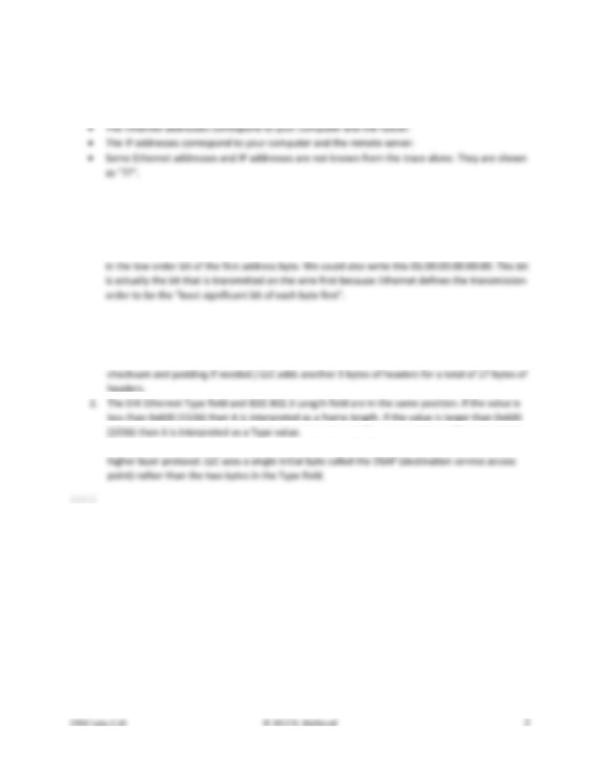
Each Ethernet frame carries a source and destination address. One of these addresses is that of your
computer. It is the source for frames that are sent, and the destination for frames that are received. But
what is the other address? Assuming you pinged a remote Internet server, it cannot be the Ethernet ad-
dress of the remote server because an Ethernet frame is only addressed to go within one LAN. Instead, it
will be the Ethernet address of the router or default gateway, such as your AP in the case of 802.11. This
is the device that connects your LAN to the rest of the Internet. In contrast, the IP addresses in the IP
block of each packet do indicate the overall source and destination endpoints. They are your computer
and the remote server.
Step 5: Broadcast Frames
The trace that you gathered above captured unicast Ethernet traffic sent between a specific source and
destination, e.g., your computer to the router. It is also possible to send multicast or broadcast Ethernet
traffic, destined for a group of computers or all computers on the Ethernet, respectively. We can tell
from the address whether it is unicast, multicast, or broadcast. Broadcast traffic is sent to a reserved
Ethernet address that has all bits set to “1”. Multicast traffic is sent to addresses that have a “1” in the
first bit sent on the wire; broadcast is a special case of multicast. Broadcast and multicast traffic is widely
used for discovery protocols, e.g., a packet sent to everyone in an effort to find the local printer.
Start a capture for broadcast and multicast Ethernet frames with a filter of “ether multicast”, wait
up to 30 seconds to record background traffic, and then stop the capture. If you do not capture any
packets with this filter then use the trace that we supplied. On most Ethernets, there is a steady chatter
of background traffic as computers exchange messages to maintain network state, which is why we try
Answer the following questions:
1. What is the broadcast Ethernet address, written in standard form as Wireshark displays it?
2. Which bit of the Ethernet address is used to determine whether it is unicast or mul-
ticast/broadcast?
Turn–in: Hand in your answers to the above questions.
Explore on your own (IEEE 802.3)
We encourage you to explore Ethernet on your own once you have completed this lab. As one possibil-
ity, recall that there are two types of Ethernet frame, IEEE 802.3 and DIX Ethernet. DIX is common and
what we considered above, while IEEE 802.3 is rare. If you are rather lucky, you may see some IEEE
802.3 frames in the trace you have captured. If not, then there are some of these packets in the trace
that we supplied. To search for IEEE 802.3 packets, enter a display filter (above the top panel of the
Wireshark window) of “llc” (that was lowercase “LLC”) because the IEEE 802.3 format has the LLC proto-
col on top of it. LLC is also present on top of IEEE 802.11 wireless, but it is not present on DIX Ethernet.
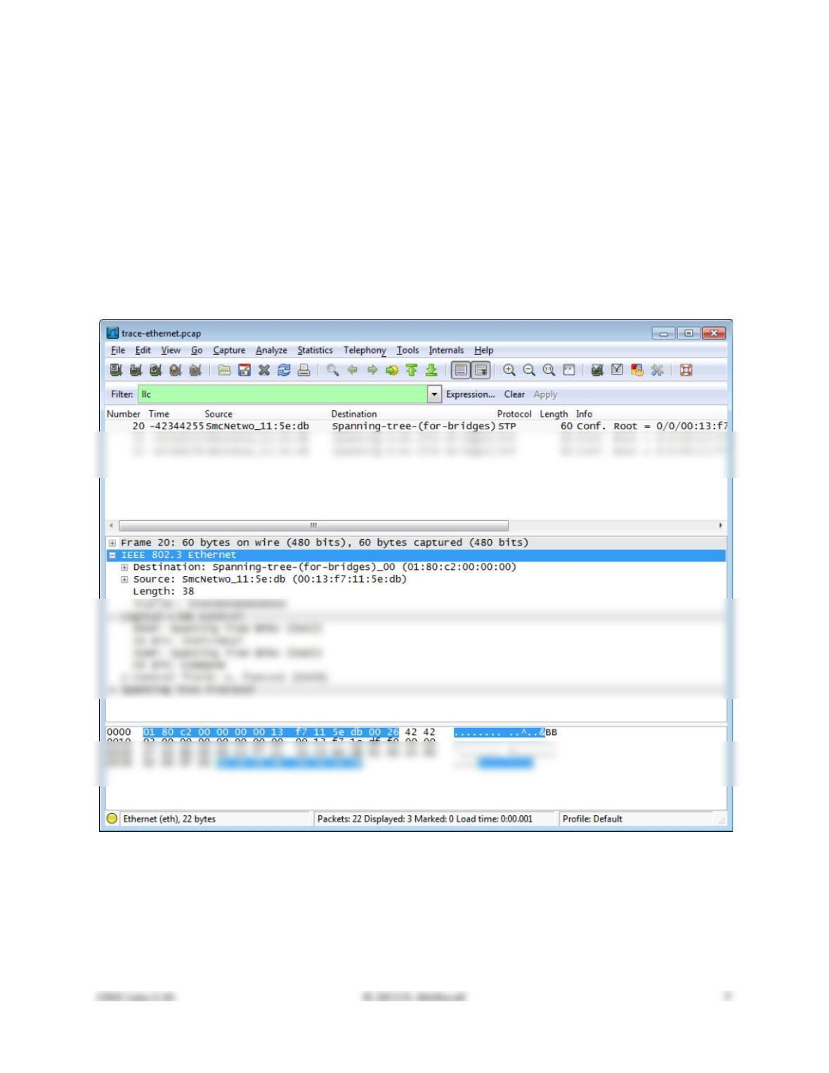
Figure 4: IEEE 802.3 frames with Ethernet and LLC header detail
Have a look at the details of an IEEE 802.3 frame, including the LLC header. The figure shows the details
for our trace. Observe that the Type field is now a Length field. In our example, the frame is short
enough that there is also padding of zeros identified as a Trailer or Padding. The changes lead to a few
questions for you to ponder:
1. How long are the combined IEEE 802.3 and LLC headers compared to the DIX Ethernet headers?
2. How does the receiving computer know whether the frame is DIX Ethernet or IEEE 802.3? Hint:
3. If IEEE 802.3 has no Type field, then how is the next higher layer determined? Use Wireshark to
look for the demultiplexing key.
Solutions – Ethernet
The solutions below are based on our capture and use of tools. Your answers will necessarily differ in the
details because they are based on your capture and use of tools in a different network setting. Nonethe-
less, we expect our solutions to help you understand whether your answers are correct.
Step 3: Ethernet Frame Structure
Figure 1: Structure of an Ethernet frame
There are several features to note:
• The destination address comes before the source address.
• The pad is not shown because the packets we examined (ping) are large enough that no pad is
Step 4: Scope of Ethernet Addresses
There are several features to note:
• The Ethernet and IP addresses will vary for your trace because different computers are involved,
but they will have the same form, e.g. 6 bytes in hexadecimal format or 4 “dotted” bytes.
Step 5: Broadcast Addresses
Answers to the questions:
1. The broadcast address is ff:ff:ff:ff:ff:ff. This is 48 bits of “all 1s”written in standard form.
2. The broadcast/multicast or “group” bit is shown by Wireshark as “…. …1 …. …. …. ….” or a one
Explore on your own (IEEE 802.3)
Answers to the questions:
1. The IEEE 802.3 header is 14 bytes, the same as DIX Ethernet. (Both also have a trailer with a
3. IEEE 802.3 adds the LLC header immediately after the IEEE 802.3 header to conveys the next