Lab Exercise – Protocol Layers
Objective
To learn how protocols and layering are represented in packets. They are key concepts for structuring
networks that are covered in §1.3 and §1.4 of your text. Review those sections before doing the lab.
Requirements
Wireshark: This lab uses the Wireshark software tool to capture and examine a packet trace. A packet
trace is a record of traffic at a location on the network, as if a snapshot was taken of all the bits that
passed across a particular wire. The packet trace records a timestamp for each packet, along with the
bits that make up the packet, from the lower–layer headers to the higher–layer contents. Wireshark runs
wget / curl: This lab uses wget (Linux and Windows) and curl (Mac) to fetch web resources. wget
and curl are command–line programs that let you fetch a URL. Unlike a web browser, which fetches
Step 1: Capture a Trace
Proceed as follows to capture a trace of network traffic; alternatively, you may use a supplied trace. We
want this trace to look at the protocol structure of packets. A simple Web fetch of a URL from a server of
your choice to your computer, which is the client, will serve as traffic.
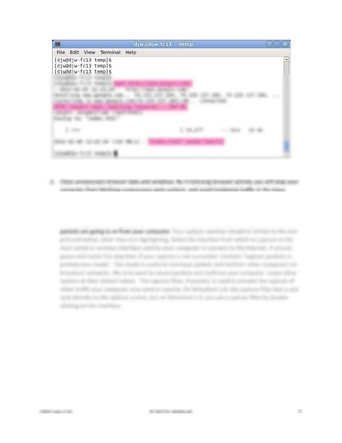
Figure 1: Using wget to fetch a URL
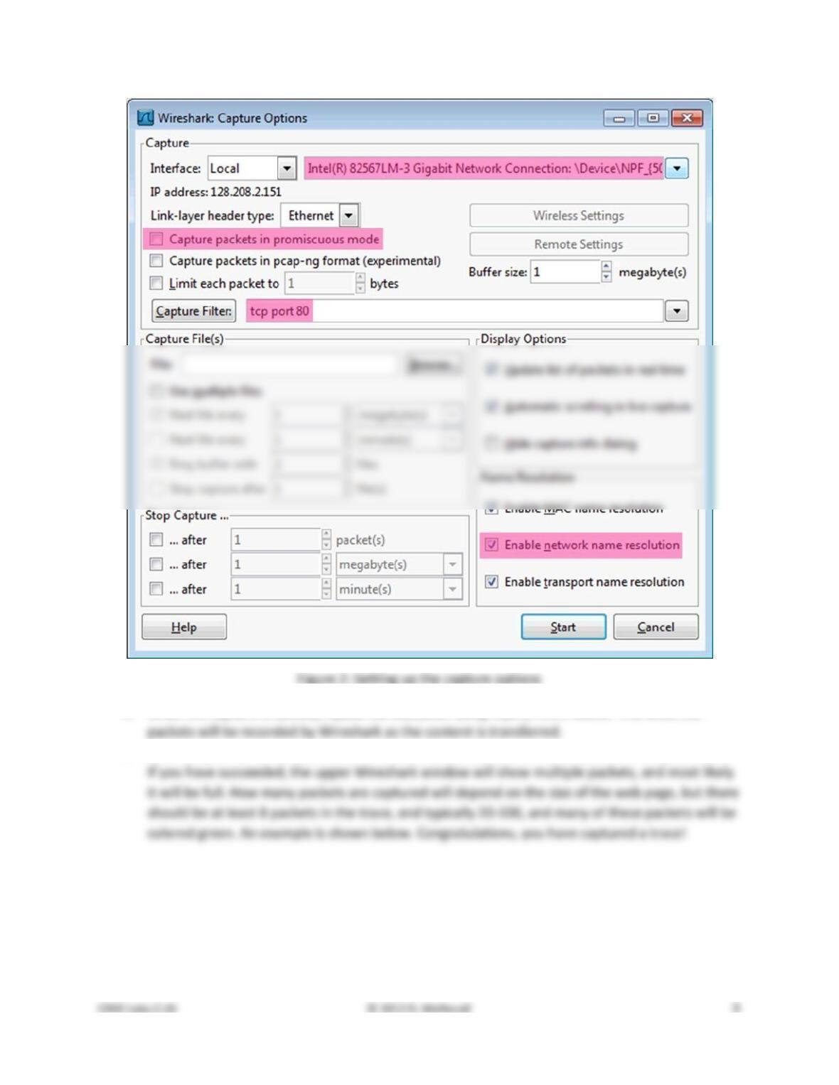
3. Launch Wireshark and start a capture with a filter of “tcp port 80” and check “enable net-
work name resolution”. This filter will record only standard web traffic and not other kinds of
packets that your computer may send. The checking will translate the addresses of the comput-
ers sending and receiving packets into names, which should help you to recognize whether the
4. When the capture is started, repeat the web fetch using wget/curl above. This time, the
5. After the fetch is successful, return to Wireshark and use the menus or buttons to stop the trace.
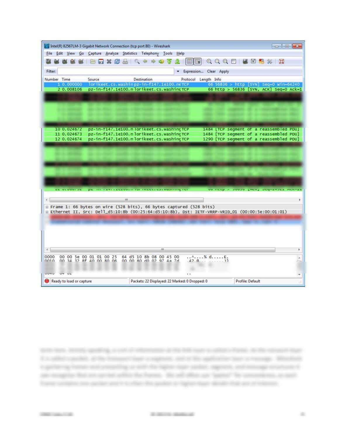
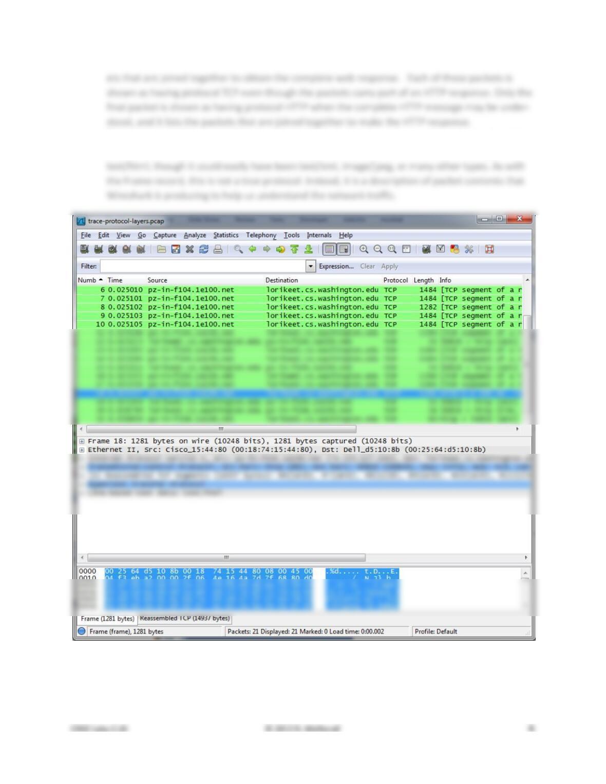
Figure 3: Packet trace of wget traffic
Step 2: Inspect the Trace
Wireshark will let us select a packet (from the top panel) and view its protocol layers, in terms of both
header fields (in the middle panel) and the bytes that make up the packet (in the bottom panel). In the
figure above, the first packet is selected (shown in blue). Note that we are using “packet” as a general
Select a packet for which the Protocol column is “HTTP” and the Info column says it is a GET. It is the
packet that carries the web (HTTP) request sent from your computer to the server. (You can click the
column headings to sort by that value, though it should not be difficult to find an HTTP packet by inspec-
tion.) Let’s have a closer look to see how the packet structure reflects the protocols that are in use.
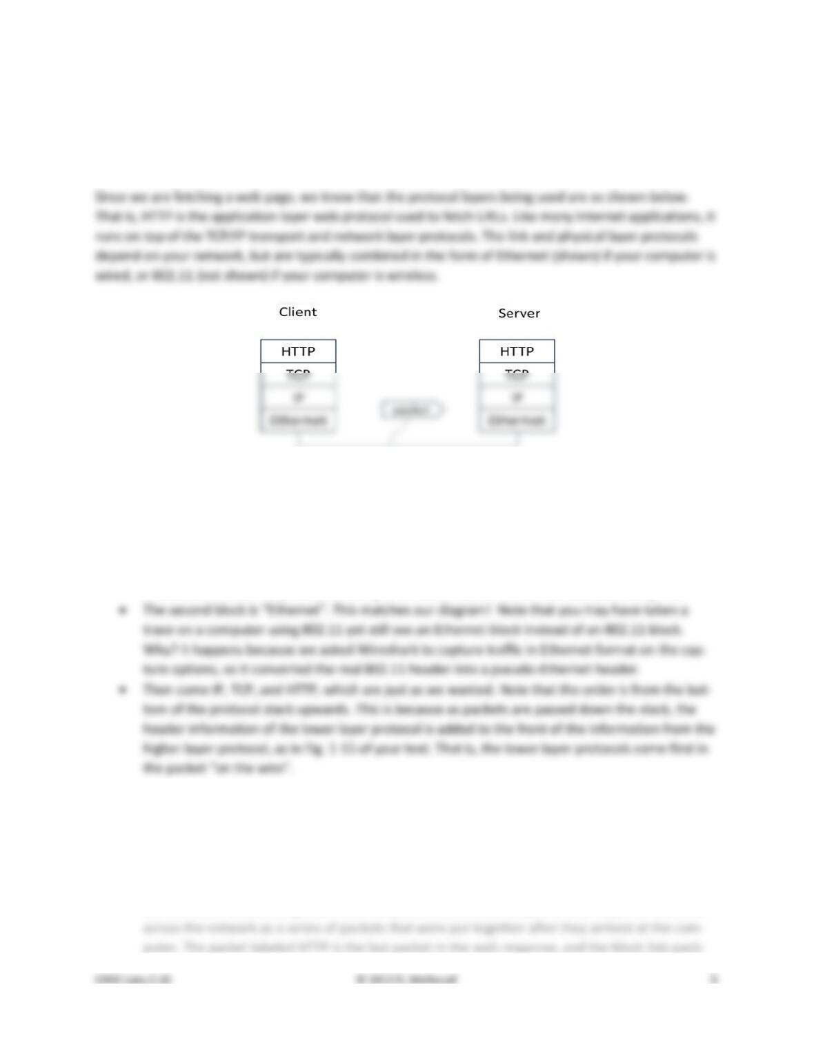
Figure 4: Protocol stack for a web fetch
With the HTTP GET packet selected, look closely to see the similarities and differences between it and our
protocol stack as described next. The protocol blocks are listed in the middle panel. You can expand each
block (by clicking on the “+” expander or icon) to see its details.
• The first Wireshark block is “Frame”. This is not a protocol, it is a record that describes overall
information about the packet, including when it was captured and how many bits long it is.
Now find another HTTP packet, the response from the server to your computer, and look at the structure
of this packet for the differences compared to the HTTP GET packet. This packet should have “200 OK” in
the Info field, denoting a successful fetch. In our trace, there are two extra blocks in the detail panel as
seen in the next figure.
• The first extra block says “[11 reassembled TCP segments …]”. Details in your capture will vary,
but this block is describing more than the packet itself. Most likely, the web response was sent
• The second extra block says “Line–based text data …”. Details in your capture will vary, but this
block is describing the contents of the web page that was fetched. In our case it is of type
Figure 5: Inspecting a HTTP “200 OK” response
Step 3: Packet Structure
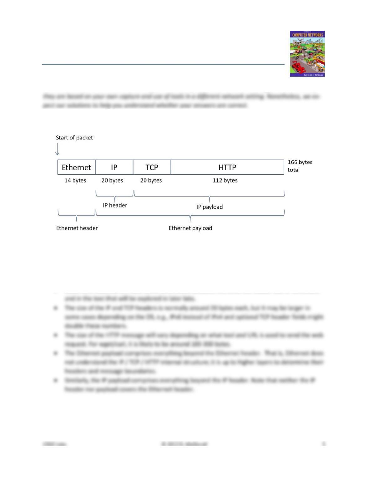
To show your understanding of packet structure, draw a figure of an HTTP GET packet that shows the
position and size in bytes of the TCP, IP and Ethernet protocol headers. Your figure can simply show the
overall packet as a long, thin rectangle. Leftmost elements are the first sent on the wire. On this draw-
ing, show the range of the Ethernet header and the Ethernet payload that IP passed to Ethernet to send
over the network. To show the nesting structure of protocol layers, note the range of the IP header and
the IP payload. You may have questions about the fields in each protocol as you look at them. We will
explore these protocols and fields in detail in future labs.
To work out sizes, observe that when you click on a protocol block in the middle panel (the block itself,
Turn–in: Hand in your packet drawing.
Step 4: Protocol Overhead
Estimate the download protocol overhead, or percentage of the download bytes taken up by protocol
overhead. To do this, consider HTTP data (headers and message) to be useful data for the network to
carry, and lower layer headers (TCP, IP, and Ethernet) to be the overhead. We would like this overhead
to be small, so that most bits are used to carry content that applications care about. To work this out,
Step 5: Demultiplexing Keys
When an Ethernet frame arrives at a computer, the Ethernet layer must hand the packet that it contains
to the next higher layer to be processed. The act of finding the right higher layer to process received
packets is called demultiplexing. We know that in our case the higher layer is IP. But how does the
1. Which Ethernet header field is the demultiplexing key that tells it the next higher layer is IP?
What value is used in this field to indicate “IP”?
2. Which IP header field is the demultiplexing key that tells it the next higher layer is TCP? What
value is used in this field to indicate “TCP”?
Turn–in: Hand in your answers to the above questions.
Explore on your own
We encourage you to explore protocols and layering once you have completed this lab. Some ideas:
• Look at a short TCP packet that carries no higher–layer data. To what entity is this packet des-
tined? After all, if it carries no higher–layer data then it does not seem very useful to a higher
layer protocol such as HTTP!
• In a classic layered model, one message from a higher layer has a header appended by the lower
Solutions – Protocol Layers
The solutions below are based on our capture and use of tools. Your answers will differ in the details if
Step 3: Packet Structure
Figure 1: Protocol layer structure of the HTTP GET packet
There are several features to note:
• The order of the headers (Ethernet, IP, TCP, HTTP) is the protocol stack from the bottom up-
wards because the lower layers are outermost in the packet as it travels through the network.
• Observant students will note some differences between the Ethernet header size in Wireshark
Step 4: Protocol Overhead
For our trace, the large download packets are each 1484 bytes. Inspecting the TCP details in one of them
shows it to carry 1430 bytes of higher–layer data. Alternatively, the Ethernet, IP, and TCP headers can be
seen to total 54 bytes. This gives an overhead of 54/1484 or 3.6%. If you do the same for your trace you
will get a slightly different number, but it is likely to be in the ballpark of 5%.
Now, the question asked for an estimate of the overhead over all downloaded packets, not just one of
them. We would expect this to be somewhat higher, but not greatly. For our trace, we have:
Step 5: Demultiplexing
Answers to the questions:
2. The demultiplexing key for IP is the Protocol field. It has value 6 when the higher layer is TCP.
Explore on your own
Answers to the questions:
• The packet is destined to the TCP protocol entity of the receiving computer, not to the applica-
tion that implements HTTP. It is a control packet exchanged between TCP peers to manage their
connection state.
• Only the first drawing will have an HTTP header inside the packet (unless the HTTP header is ex-
tremely long). The second drawing will have HTTP payload data but no HTTP header.
[END]