Chapter 7
Sheet-Metal Forming Processes
Questions
7.1 Select any three topics from Chapter 2, and,
with specific examples for each, show their rel-
evance to the topics described in this chapter.
•Yield stress and elastic modulus, described
in Section 2.2 starting on p. 30, have,
7.2 Do the same as for Question 7.1, but for Chap-
ter 3.
tion 3.4 starting on p. 91), as well as the
Section 3.3.4) have a major influence on
formability (Section 7.7 on p. 397).
7.3 Describe (a) the similarities and (b) the differ-
ences between the bulk-deformation processes
described in Chapter 6 and the sheet-metal
craft. Structural parts that are made by forging
in Fig. 7.7 on p. 354, including its height and
© 2008 Pearson Education, Inc., Upper Saddle River, NJ. All rights reserved.
This material is protected by Copyright and written permission should be obtained from the publisher prior to any prohibited
reproduction, storage in a retrieval system, or transmission in any form or by any means, electronic, mechanical, photocopying, recording, or
likewise. For information regarding permission(s), write to:
Rights and Permissions Department, Pearson Education, Inc., Upper Saddle River, NJ 07458.
(a) the shear strength of the material and its
strain-hardening exponent; they increase
and 7.6.
tion, and its influence on edge quality and hard-
7.6 Inspect a common paper punch and comment
on the shape of the tip of the punch as com-
7.7 Explain how you would estimate the tempera-
ture rise in the shear zone in a shearing opera-
tion.
up to that particular shear strain, just as we
7.8 As a practicing engineer in manufacturing, why
would you be interested in the shape of the
It is apparent that all this information should
7.9 Do you think the presence of burrs can be ben-
eficial in certain applications? Give specific ex-
small cross-sectional area to be supported by
the spindle or shaft on which it is mounted. The
7.10 Explain why there are so many different types
of tool and die materials used for the processes
described in this chapter.
7.11 Describe the differences between compound,
© 2008 Pearson Education, Inc., Upper Saddle River, NJ. All rights reserved.
This material is protected by Copyright and written permission should be obtained from the publisher prior to any prohibited
reproduction, storage in a retrieval system, or transmission in any form or by any means, electronic, mechanical, photocopying, recording, or
likewise. For information regarding permission(s), write to:
Rights and Permissions Department, Pearson Education, Inc., Upper Saddle River, NJ 07458.
7.12 It has been stated that the quality of the
subsequent forming operations, such as bend-
7.13 Explain why and how various factors influence
springback in bending of sheet metals.
(7.10) on p. 364 gives the relation between ra-
dius and thickness. Thus, increasing bend ra-
7.14 Does the hardness of a sheet metal have an ef-
fect on its springback in bending? Explain.
Recall from Section 2.6.8 on p. 54 that hard-
ness is related to strength, such as yield stress
as shown in Fig. 2.24 on p. 55. Referring to
Eq. (7.10) on p. 364 , also note that the yield
stress, Y, has a significant effect on springback.
7.15 As noted in Fig. 7.16, the state of stress shifts
from plane stress to plane strain as the ratio
gions, hence the situation is one of basically
plane stress. On the other hand, the greater
effect on the relative position of the curves
is directly attributable to the difference in their
yield stress. Likewise, comparing curves (b),
(d), and (e), note that they are all stainless
higher R/t ratios than soft ones. Explain why.
Thus, hard material conditions mean lower ten-
sile reduction and, therefore, higher R/T ra-
tios. In other words, for a constant sheet thick-
ness, T, the bend radius, R, has to be larger for
higher bendability.
7.18 Why do tubes have a tendency to buckle when
bent? Experiment with a straight soda straw,
the other half under compressive stresses. Also,
compressing a column tends to buckle it, de-
© 2008 Pearson Education, Inc., Upper Saddle River, NJ. All rights reserved.
This material is protected by Copyright and written permission should be obtained from the publisher prior to any prohibited
reproduction, storage in a retrieval system, or transmission in any form or by any means, electronic, mechanical, photocopying, recording, or
likewise. For information regarding permission(s), write to:
Rights and Permissions Department, Pearson Education, Inc., Upper Saddle River, NJ 07458.
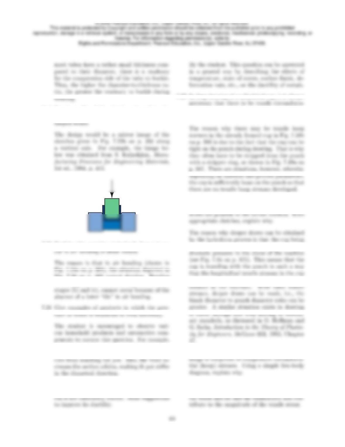
7.19 Based on Fig. 7.22, sketch and explain the
shape of a U-die used to produce channel-
7.20 Explain why negative springback does not oc-
Fig. 7.20 on p. 365 cannot develop. Bending
in the opposite direction, as depicted between
along the rim of many sheet-metal cooking pots,
a bead is formed to confine the burr and prevent
7.22 Assume that you are carrying out a sheet-
forming operation and you find that the mate-
tial stresses on the element in the cup wall, a
shown in Fig. 7.50b? Explain.
7.24 When comparing hydroforming with the deep-
drawing process, it has been stated that deeper
formed is pushed against the punch by the hy-
wall are reduced, by virtue of the frictional re-
7.25 We note in Fig. 7.50a that element A in the
This is shown simply by a free-body diagram,
as illustrated below. Note that friction between
© 2008 Pearson Education, Inc., Upper Saddle River, NJ. All rights reserved.
This material is protected by Copyright and written permission should be obtained from the publisher prior to any prohibited
reproduction, storage in a retrieval system, or transmission in any form or by any means, electronic, mechanical, photocopying, recording, or
likewise. For information regarding permission(s), write to:
Rights and Permissions Department, Pearson Education, Inc., Upper Saddle River, NJ 07458.
+
7.27 Explain why increasing the normal anisotropy,
R, improves the deep drawability of sheet met-
7.29 If you could control the state of strain in a
sheet-forming operation, would you rather work
on the left or the right side of the forming-limit
diagram? Explain.
7.30 Comment on the effect of lubrication of the
punch surfaces on the limiting drawing ratio in
(Fig. 7.50b on p. 388). Thus, deep drawabil-
ity will decrease, hence the limited drawing ra-
tio will also decrease. Conversely, not lubricat-
ing the punch will allow the cup to travel with
the punch, thus reducing the longitudinal ten-
sile stress.
7.31 Comment on the role of the size of the circles
large the circles are as compared with the size
of the crack that has developed. As for square
answers, but should not be considered the only
acceptable ones.
(a) The blank diameter affects the force
duction and hence the work involved.
© 2008 Pearson Education, Inc., Upper Saddle River, NJ. All rights reserved.
This material is protected by Copyright and written permission should be obtained from the publisher prior to any prohibited
reproduction, storage in a retrieval system, or transmission in any form or by any means, electronic, mechanical, photocopying, recording, or
likewise. For information regarding permission(s), write to:
Rights and Permissions Department, Pearson Education, Inc., Upper Saddle River, NJ 07458.
ditional energy has to be supplied to over-
7.33 Explain why the simple tension line in the
forming-limit diagram in Fig. 7.63a states that
is -0.5. Recall that this value is for a mate-
7.34 What are the reasons for developing forming-
limit diagrams? Do you have any specific criti-
The reasons for developing the FLD diagrams
are self-evident by reviewing Section 7.7.1.
7.35 Explain the reasoning behind Eq. (7.20) for
normal anisotropy, and Eq. (7.21) for planar
avoid it? Would ears serve any useful purposes?
Earing, described in Section 7.6.1 on p. 394, is
7.37 It was stated in Section 7.7.1 that the thicker
In forming-limit diagrams, increasing thickness
The rolled sheet is stronger in the direction
on p. 394, the directions are at about ±45◦on
7.39 Describe the factors that influence the size and
length of beads in sheet-metal forming opera-
strength to influence the Rvalue of sheet met-
als? Explain.
values.
7.41 Equation (7.23) gives a general rule for dimen-
sional relationships for successful drawing with-
© 2008 Pearson Education, Inc., Upper Saddle River, NJ. All rights reserved.
This material is protected by Copyright and written permission should be obtained from the publisher prior to any prohibited
reproduction, storage in a retrieval system, or transmission in any form or by any means, electronic, mechanical, photocopying, recording, or
likewise. For information regarding permission(s), write to:
Rights and Permissions Department, Pearson Education, Inc., Upper Saddle River, NJ 07458.
7.42 Explain why the three broken lines (simple ten-
sion, plane strain, and equal biaxial stretching)
tio effect in plastic deformation. In other words,
the minor strain is one-half the major strain in
and explain which of the processes described in
Chapters 6 and 7 can be used to make those
part. Explain your reasoning.
have a common aspect as far as properties of
By the student, based on the type of products
that are made by the processes described in
7.46 Make a summary of the types of defects found
in sheet-metal forming processes, and include
brief comments on the reason(s) for each de-
7.47 Which of the processes described in this chap-
ter use only one die? What are the advantages
of using only one die?
Comment on how these methods could improve
© 2008 Pearson Education, Inc., Upper Saddle River, NJ. All rights reserved.
This material is protected by Copyright and written permission should be obtained from the publisher prior to any prohibited
reproduction, storage in a retrieval system, or transmission in any form or by any means, electronic, mechanical, photocopying, recording, or
likewise. For information regarding permission(s), write to:
Rights and Permissions Department, Pearson Education, Inc., Upper Saddle River, NJ 07458.
Question 7.48 can be implemented. Would pro-
duction rate affect your designs? Explain.
may involve electric heating elements in the
strains be eliminated?
p. 301. Another solution is to modify the de-
7.51 In order to improve its ductility, a coil of sheet
7.6.1 would actually predict this behavior. The
7.52 What effects does friction have on a forming-
limit diagram? Explain.
7.53 Why are lubricants generally used in sheet-
metal forming? Explain, giving examples.
lem 7.52. As an example of this, lightweight
oils are commonly applied in stretch forming
7.54 Through changes in clamping, a sheet-metal
a negative minor strain can be induced, then
more in this direction and thus allow larger ma-
suitable casting operation. Note that in either
on the part of the student. Consider, for exam-
ple:
© 2008 Pearson Education, Inc., Upper Saddle River, NJ. All rights reserved.
This material is protected by Copyright and written permission should be obtained from the publisher prior to any prohibited
reproduction, storage in a retrieval system, or transmission in any form or by any means, electronic, mechanical, photocopying, recording, or
likewise. For information regarding permission(s), write to:
Rights and Permissions Department, Pearson Education, Inc., Upper Saddle River, NJ 07458.
aircraft wing panels in Fig. 7.30 on p. 372.
Also, continuous parts such as roll-formed
7.57 Due to preferred orientation (see Section 3.5),
materials such as iron can have higher mag-
By the student. There should be a realization
that there is a maximum magnetism with fully
aligned grains, and zero magnetism with fully
7.58 Explain why a metal with a fine-grain mi-
crostructure is better suited for fine blanking
grain boundaries (in the volume that is frac-
7.59 What are the similarities and differences be-
tween roll forming described in this chapter and
shape rolling in Chapter 6?
bendability. Do they have a similar effects on
formability?
son is that stringers are hard and brittle inclu-
7.61 In Fig. 7.56, the caption explains that zinc has
a high c/a ratio, whereas titanium has a low
ratio. Why does this have relevance to limiting
drawing ratio?
slip in Section 3.3. For titanium, the c/a ra-
tio in its hcp structure is low, hence there are
7.62 Review Eqs. (7.12) through (7.14) and explain
because the deformation in incremental form-
ing is highly localized. Note that the strain re-
© 2008 Pearson Education, Inc., Upper Saddle River, NJ. All rights reserved.
This material is protected by Copyright and written permission should be obtained from the publisher prior to any prohibited
reproduction, storage in a retrieval system, or transmission in any form or by any means, electronic, mechanical, photocopying, recording, or
likewise. For information regarding permission(s), write to:
Rights and Permissions Department, Pearson Education, Inc., Upper Saddle River, NJ 07458.
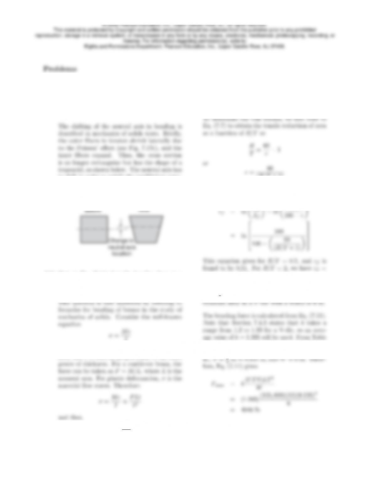
7.63 Referring to Eq. (7.5), it is stated that actual
values of eoare significantly higher than val-
ues of ei, due to the shifting of the neutral axis
during bending. With an appropriate sketch,
explain this phenomenon.
to shift in order to satisfy the equilibrium equa-
tions regarding forces and internal moments in
bending.
7.64 Note in Eq. (7.11) that the bending force is a
function of t2. Why? (Hint: Consider bending-
moment equations in mechanics of solids.)
I
where cis directly proportional to the thick-
ness, and Iis directly proportional to the third
7.65 Calculate the minimum tensile true fracture
strain that a sheet metal should have in order
to be bent to the following R/t ratios: (a) 0.5,
(b) 2, and (c) 4. (See Table 7.2.)
(R/T + 1)
The strain at fracture can be calculated from
Eq. (2.10) as
0.22, and for R/T = 4, ǫf= 0.13.
7.66 Estimate the maximum bending force required
for a 1
8-in. thick and 12-in. wide Ti-5Al-2.5Sn
3.14, we find that UTS=860 MPa = 125,000 psi.
Also, the problem statement gives us L= 12
7.67 In Example 7.4, calculate the work done by the
© 2008 Pearson Education, Inc., Upper Saddle River, NJ. All rights reserved.
This material is protected by Copyright and written permission should be obtained from the publisher prior to any prohibited
reproduction, storage in a retrieval system, or transmission in any form or by any means, electronic, mechanical, photocopying, recording, or
likewise. For information regarding permission(s), write to:
Rights and Permissions Department, Pearson Education, Inc., Upper Saddle River, NJ 07458.
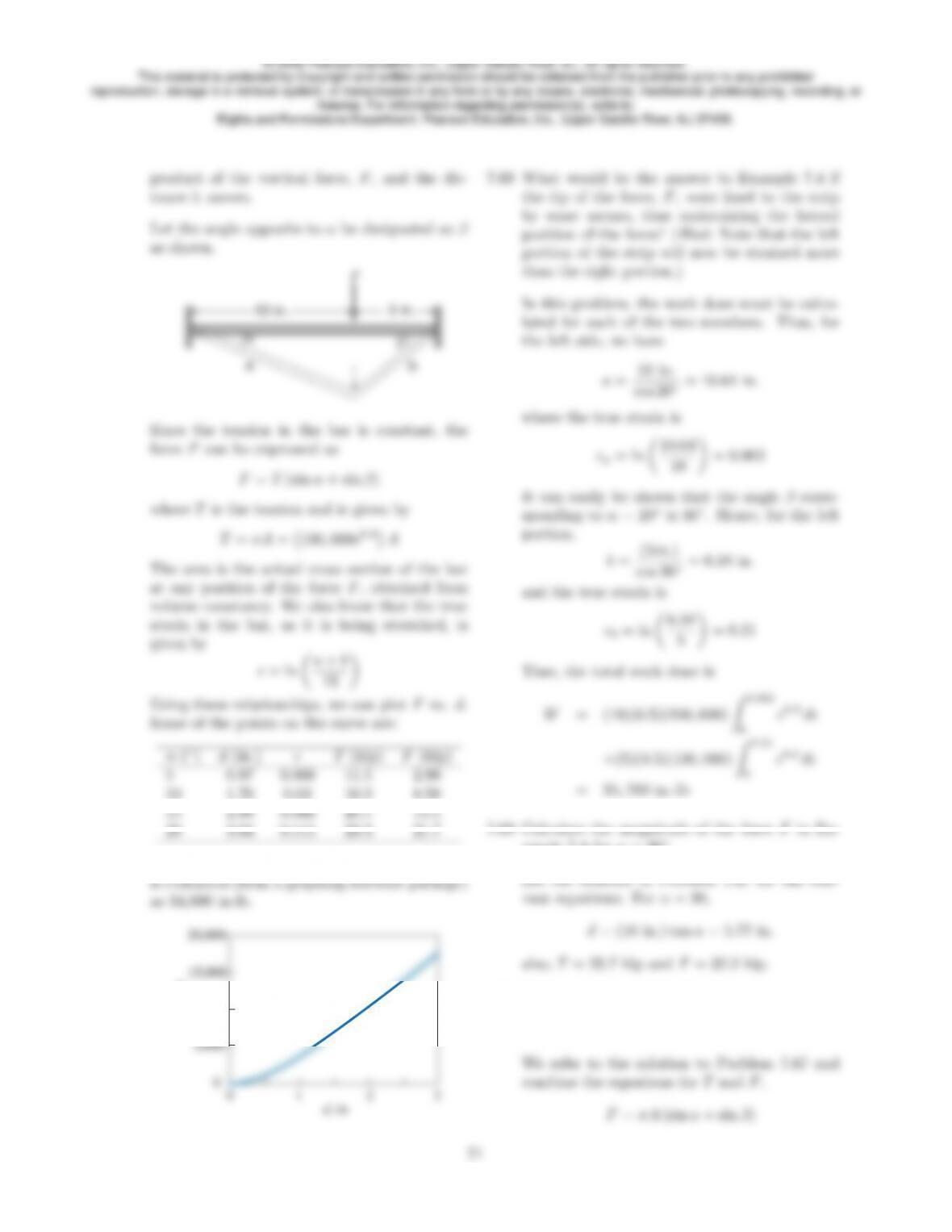
The curve is plotted as follows and the integral
ample 7.4 for α= 30◦.
© 2008 Pearson Education, Inc., Upper Saddle River, NJ. All rights reserved.
This material is protected by Copyright and written permission should be obtained from the publisher prior to any prohibited
reproduction, storage in a retrieval system, or transmission in any form or by any means, electronic, mechanical, photocopying, recording, or
likewise. For information regarding permission(s), write to:
Rights and Permissions Department, Pearson Education, Inc., Upper Saddle River, NJ 07458.