Chapter 6
Bulk Deformation Processes
Questions
Forging
6.1 How can you tell whether a certain part is
forged or cast? Describe the features that you
than forged parts. Surface characteristics and
portant in closed-die forging?
6.3 What are the advantages and limitations of a
cogging operation? Of die inserts in forging?
6.4 Explain why there are so many different kinds
of forging machines available.
volved in equipment selection may be summa-
© 2008 Pearson Education, Inc., Upper Saddle River, NJ. All rights reserved.
This material is protected by Copyright and written permission should be obtained from the publisher prior to any prohibited
reproduction, storage in a retrieval system, or transmission in any form or by any means, electronic, mechanical, photocopying, recording, or
likewise. For information regarding permission(s), write to:
Rights and Permissions Department, Pearson Education, Inc., Upper Saddle River, NJ 07458.

6.5 Devise an experimental method whereby you
can measure the force required for forging
only the flash in impression-die forging. (See
Fig. 6.15a.)
An experimental method to determine the
forces required to forge only the flash (for an
part and the flash, respectively, can be mea-
6.6 A manufacturer is successfully hot forging a cer-
tain part, using material supplied by Company
A. A new supply of material is obtained from
Company B, with the same nominal composi-
tion of the major alloying elements as that of
the material from Company A. However, it is
found that the new forgings are cracking even
though the same procedure is followed as be-
regarding minor elements or impurity levels.
6.7 Explain why there might be a change in the
density of a forged product as compared to that
of the cast blank.
decrease after forging due to void formation.
6.8 Since glass is a good lubricant for hot extrusion,
would you use glass for impression-die forging
as well? Explain.
Glass, in various forms, is used for hot forging
operations. However, in impression-die forging,
6.9 Describe and explain the factors that influence
workpiece interface in cogging indicates that
the factors that influence spreading are:
(a) Friction: the lower the friction, the more
the spreading because of reduced lateral
resistance to material flow.
(b) Width-to-thickness ratio of the workpiece:
the higher this ratio, the lower the spread-
6.10 Why are end grains generally undesirable in
forged products? Give examples of such prod-
ucts.
As discussed in Section 6.2.5 starting on
© 2008 Pearson Education, Inc., Upper Saddle River, NJ. All rights reserved.
This material is protected by Copyright and written permission should be obtained from the publisher prior to any prohibited
reproduction, storage in a retrieval system, or transmission in any form or by any means, electronic, mechanical, photocopying, recording, or
likewise. For information regarding permission(s), write to:
Rights and Permissions Department, Pearson Education, Inc., Upper Saddle River, NJ 07458.
6.11 Explain why one cannot produce a finished
forging in one press stroke, starting with a
blank.
Forgings are typically produced through a series
termediate annealing, thus allowing less
ductile materials to be forged to compli-
cated shapes.
it can be seen that each operation will
6.12 List the advantages and disadvantages of using
a lubricant in forging operations.
The advantages include:
from the environment, especially in hot
forging, and also act as a parting agent.
(d) the lubricant must subsequently be re-
moved from the part surface, an additional
and difficult operation;
(e) disposal of the lubricant can present envi-
cool dies. Consequently, the flash has higher
strength than the hotter workpiece in the die
6.14 By inspecting some forged products (such as
a pipe wrench or coins), you can see that the
By the student. It is much easier and economi-
cal to machine cavities in a die (thus producing
6.15 It was stated that three factors that influ-
ence spreading in rolling are (a) the width-to-
© 2008 Pearson Education, Inc., Upper Saddle River, NJ. All rights reserved.
This material is protected by Copyright and written permission should be obtained from the publisher prior to any prohibited
reproduction, storage in a retrieval system, or transmission in any form or by any means, electronic, mechanical, photocopying, recording, or
likewise. For information regarding permission(s), write to:
Rights and Permissions Department, Pearson Education, Inc., Upper Saddle River, NJ 07458.
6.16 Explain how you would go about applying
front and back tensions to sheet metals during
rolling.
the braking torque on the pay-off reel or reduc-
forces. Which property(ies) of the roll material
can be increased to reduce flattening? Why?
6.18 Describe the methods by which roll flattening
can be reduced.
Roll flattening can be reduced by:
6.19 Explain the technical and economic reasons for
taking larger rather than smaller reductions per
pass in flat rolling.
6.20 List and explain the methods that can be used
to reduce the roll force.
(a) using smaller-diameter rolls,
(b) taking lower reduction per pass,
6.21 Explain the advantages and limitations of using
in flat rolling are the following:
(e) the smaller diameter rolls are less costly
and easier to replace and maintain.
The disadvantages include:
cessfully for the production of bearing races.
However, when the bearing race diameter is
supply is not reduced with a larger race size.
© 2008 Pearson Education, Inc., Upper Saddle River, NJ. All rights reserved.
This material is protected by Copyright and written permission should be obtained from the publisher prior to any prohibited
reproduction, storage in a retrieval system, or transmission in any form or by any means, electronic, mechanical, photocopying, recording, or
likewise. For information regarding permission(s), write to:
Rights and Permissions Department, Pearson Education, Inc., Upper Saddle River, NJ 07458.
6.23 Describe the importance of controlling roll
Control of tandem rolling is especially impor-
tant because the conditions at a particular
Consider that it is possible to apply a large
6.25 In addition to rolling, the thickness of plates
and sheets can also be reduced by simply
stretching. Would this process be feasible for
high-volume production? Explain.
feasible process, there are several significant
limitations associated with it, as compared to
rolling:
strain-hardening exponent, n.
(c) As the sheet is stretched, the surface finish
(e) There would be major difficulties in-
6.26 In Fig. 6.33, explain why the neutral point
moves towards the roll-gap entry as friction in-
uct in flat rolling is not crowned?
deformation of the work rolls.
(c) Apply a corrective moment to the shafts
of the work rolls.
6.28 List the possible consequences of rolling at (a)
too high of a speed and (b) too low of a speed.
lead to a condition where the rolls slip
against the workpiece. This can lead to a
© 2008 Pearson Education, Inc., Upper Saddle River, NJ. All rights reserved.
This material is protected by Copyright and written permission should be obtained from the publisher prior to any prohibited
reproduction, storage in a retrieval system, or transmission in any form or by any means, electronic, mechanical, photocopying, recording, or
likewise. For information regarding permission(s), write to:
Rights and Permissions Department, Pearson Education, Inc., Upper Saddle River, NJ 07458.
ish.
6.29 Rolling may be described as a continuous forg-
ing operation. Is this description appropriate?
6.30 Referring to appropriate equations, explain why
titanium carbide is used as the work roll in
Sendzimir mills, but not generally in other
rolling mill configurations.
The main reason that titanium carbide is used
6.31 It was stated that the extrusion ratio, die ge-
6.32 How would you go about preventing centerburst
defects in extrusion? Explain why your meth-
die angle and extrusion ratio. These defects can
6.33 How would you go about making a stepped
extrusion that has increasingly larger cross-
sections along its length? Is it possible? Would
your process be economical and suitable for
high production runs? Explain.
For shorter pieces, it is possible to make a die
© 2008 Pearson Education, Inc., Upper Saddle River, NJ. All rights reserved.
This material is protected by Copyright and written permission should be obtained from the publisher prior to any prohibited
reproduction, storage in a retrieval system, or transmission in any form or by any means, electronic, mechanical, photocopying, recording, or
likewise. For information regarding permission(s), write to:
Rights and Permissions Department, Pearson Education, Inc., Upper Saddle River, NJ 07458.
6.34 Note from Eq. (6.54) that, for low values of the
extrusion ratio, such as R= 2, the ideal ex-
principle and is correct. Note that the extru-
sion pressure, p, acts on the (undeformed) billet
area. Consequently, it is not necessary that its
6.35 In hydrostatic extrusion, complex seals are used
between the ram and the container, but not be-
tween the extrusion and the die. Explain why.
occur in (a) extrusion and (b) drawing.
tion 6.4.4 starting on p. 318. Examples include
poor surface finish or surface cracking (such
6.37 What is a land in a die? What is its function?
What are the advantages and disadvantages to
having no land?
not affect dimensions, since die wear mainly oc-
curs on the inlet side of the die. The disadvan-
6.38 Under what circumstances is backwards extru-
sion preferable to direct extrusion? When is
hydrostatic extrusion preferable to direct extru-
it is obvious that the main difference is that
in backward extrusion the billet is stationary,
and in direct extrusion it is moving relative to
the container walls. The main advantage be-
rect extrusion (see Fig. 6.47a)? Why is there no
container liner used in hydrostatic extrusion?
sive to replace a liner than to replace the entire
container. In hydrostatic extrusion, the billet
6.40 We have seen that in rod and wire drawing, the
maximum die pressure is at the die entry. Why?
The reason is that at the die entry, the state
© 2008 Pearson Education, Inc., Upper Saddle River, NJ. All rights reserved.
This material is protected by Copyright and written permission should be obtained from the publisher prior to any prohibited
reproduction, storage in a retrieval system, or transmission in any form or by any means, electronic, mechanical, photocopying, recording, or
likewise. For information regarding permission(s), write to:
Rights and Permissions Department, Pearson Education, Inc., Upper Saddle River, NJ 07458.
6.41 Describe the conditions under which wet draw-
of wire that can be dipped fully in the lubri-
6.42 Name the important process variables in draw-
p. 320. The important variables include:
•Yield stress, Y; it directly affects the draw
for encouraging lubricant entrainment.
•Friction coefficient, µ. The friction coef-
figuration. Also note that in a tandem opera-
tion, the front tension of one segment becomes
6.44 Refer to Fig. 6.60 and assume that reduction in
lowing situations: (a) frictionless, (b) with fric-
for drawing and extrusion predict the draw
stress or extrusion pressure, but do not show
p. 321. However, a qualitative sketch of the die
pressure can be generated based on the physi-
cal understanding of the friction hill and asso-
© 2008 Pearson Education, Inc., Upper Saddle River, NJ. All rights reserved.
This material is protected by Copyright and written permission should be obtained from the publisher prior to any prohibited
reproduction, storage in a retrieval system, or transmission in any form or by any means, electronic, mechanical, photocopying, recording, or
likewise. For information regarding permission(s), write to:
Rights and Permissions Department, Pearson Education, Inc., Upper Saddle River, NJ 07458.

6.46 Why does the die pressure in drawing decreases
toward the die exit?
6.47 What is the magnitude of the die pressure at
the die exit for a drawing operation that is be-
ing carried out at the maximum reduction per
pass?
pressure in a normal drawing operation, as de-
6.48 Explain why the maximum reduction per pass
in drawing should increase as the strain-
hardening exponent, n, increases.
dergo higher reductions per pass, as can also be
seen in Example 6.8.
6.49 If, in deriving Eq. (6.74), we include friction,
will the maximum reduction per pass be the
same (that is, 63%), higher, or lower? Explain.
The effect of back pressure is similar to that of
back tension in rolling (see Figs. 6.35 on p. 295
and 6.62 on p. 322), namely, the pressure drops.
By observing Figs. 6.12 on p. 276 and 6.13b
on p. 277, we note that the higher the h/L ra-
tio, the more nonuniform the deformation of
the material. For example, keeping hconstant
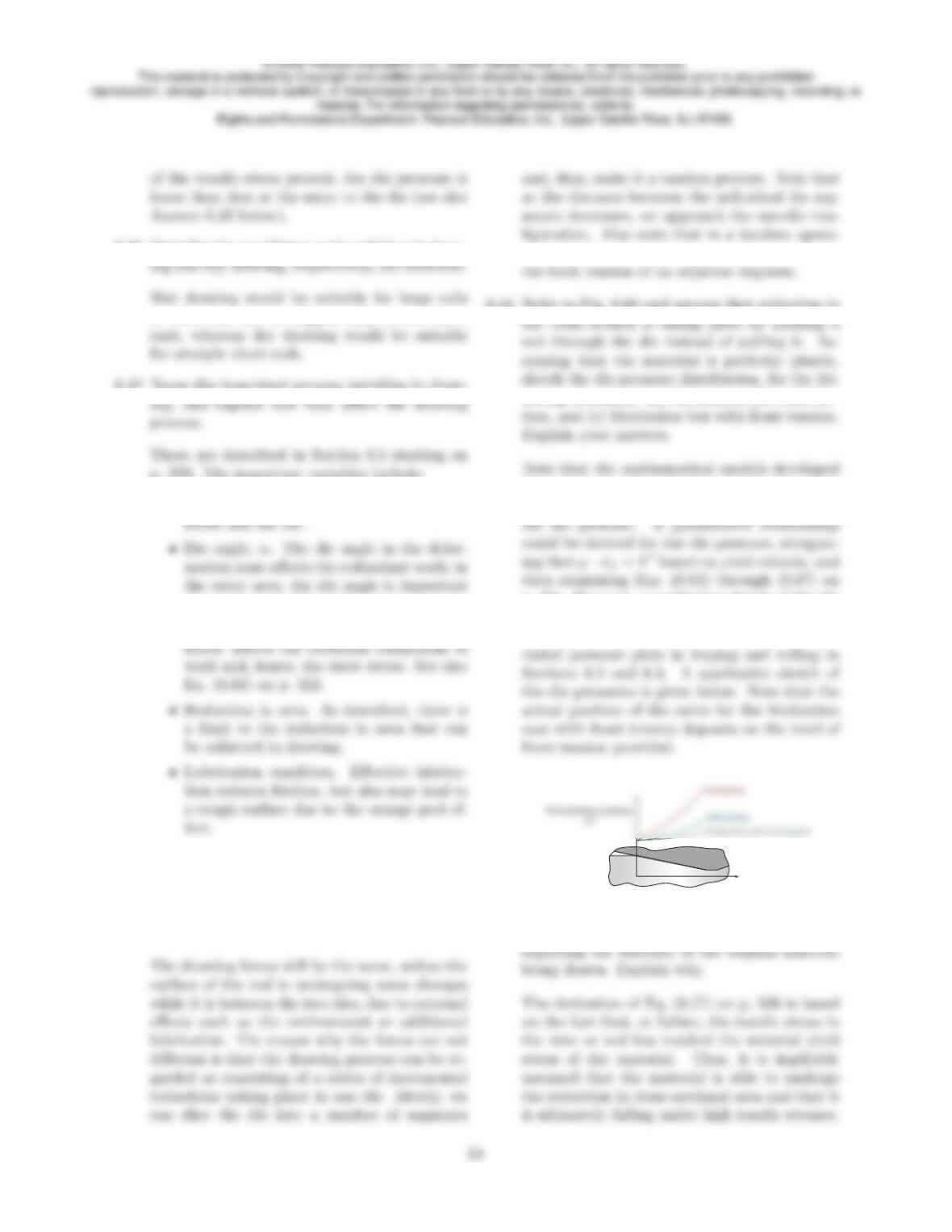
6.52 Describe the reasons for the development of the
swaging process.
(b) capacity to produce internal profiles on
long workpieces,
(c) compact equipment,
place within a sheath of a soft metal, such as
copper or lead. Why would this procedure be
effective?
The main reason that steel wire drawing takes
place in a sheath of a softer metal is to reduce
© 2008 Pearson Education, Inc., Upper Saddle River, NJ. All rights reserved.
This material is protected by Copyright and written permission should be obtained from the publisher prior to any prohibited
reproduction, storage in a retrieval system, or transmission in any form or by any means, electronic, mechanical, photocopying, recording, or
likewise. For information regarding permission(s), write to:
Rights and Permissions Department, Pearson Education, Inc., Upper Saddle River, NJ 07458.
6.54 Recognizing that it is very difficult to manufac-
ture a die with a submillimeter diameter, how
would you produce a 10 µm-diameter wire?
otherwise, the wires will weld together during
6.55 What changes would you expect in the strength,
dies? Why?
6.56 With respect to the topics covered in this chap-
The student is encouraged to provide several
specific examples. For example, friction is de-
6.57 Choose any three topics from Chapter 2 and
with a specific example for each, show their rel-
evance to the topics covered in this chapter.
6.58 Same as Question 6.57 but for Chapter 3.
and apply it to a discussion of cold versus hot
6.59 List and explain the reasons that there are so
The student should elaborate further with spe-
6.61 Make a summary of the types of defects found
in the processes described in this chapter. For
© 2008 Pearson Education, Inc., Upper Saddle River, NJ. All rights reserved.
This material is protected by Copyright and written permission should be obtained from the publisher prior to any prohibited
reproduction, storage in a retrieval system, or transmission in any form or by any means, electronic, mechanical, photocopying, recording, or
likewise. For information regarding permission(s), write to:
Rights and Permissions Department, Pearson Education, Inc., Upper Saddle River, NJ 07458.
p. 269. The equivalent version of Fig. 6.4 on
p. 269 is shown below.
dx
x
y
y
Using the stresses as shown in part (b), we have,
from equilibrium and assuming unit width,
the text it is compressive. Therefore, Eq. (6.11)
becomes
σy+σy=2
√3Y=Y′
σy=Ce−2µx/h
Using the boundary conditions that σx= 0
value of Cas
eter, up to a reduction of 70%, for the cases
of (a) no friction between the flat dies and the
specimen, (b) µ= 0.25, and (c) µ= 0.5. Ignore
barreling and use average-pressure formulas.
For annealed copper we have, from Table 2.3 on
h
From volume constancy, we have
π
oho=π
p. 272 as:
F=Yf1 + 2µr
3hπr2
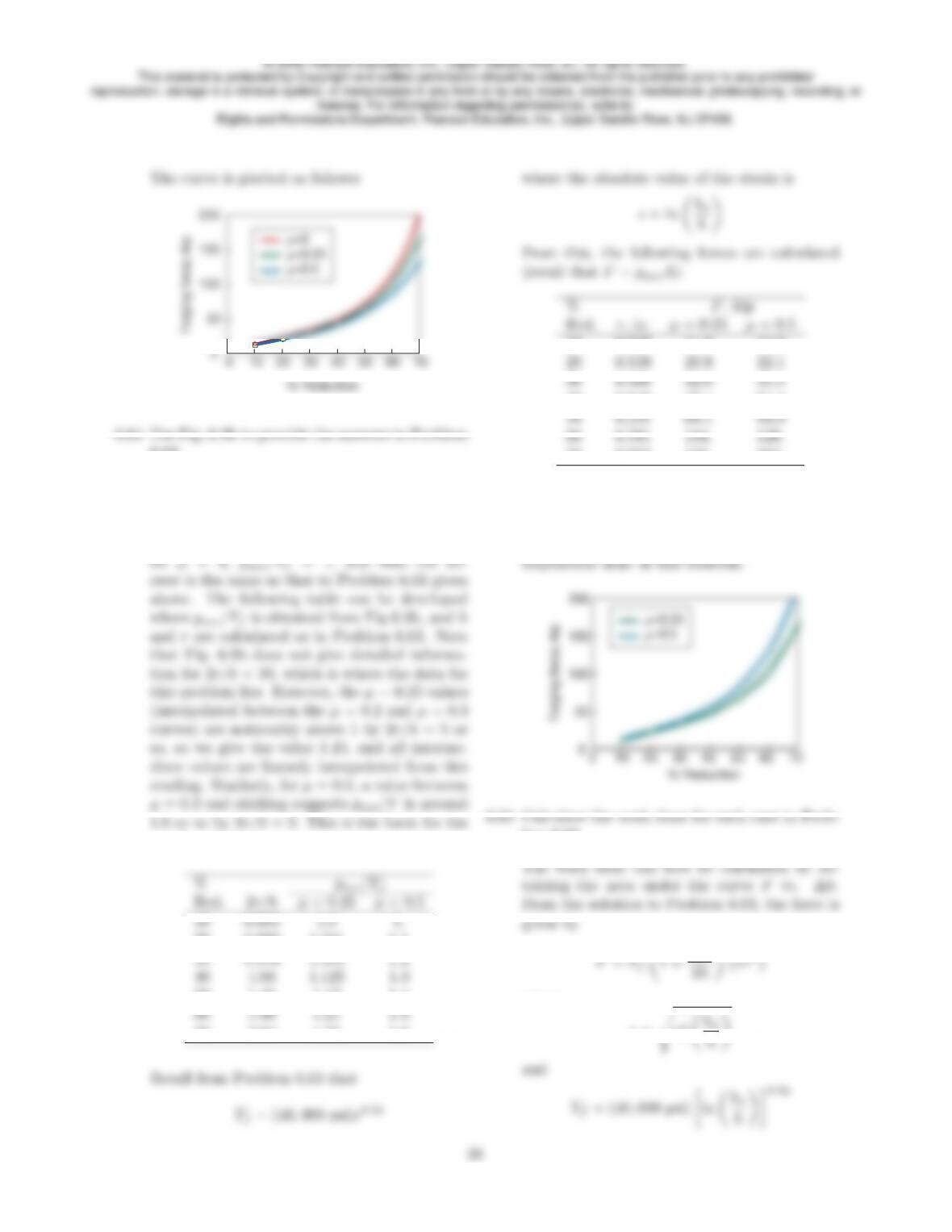
Some of the points on the curves are the follow-
10 11.9 12.4 13.1
30 29.6 31.7 33.8
50 59.3 66.3 73.6
60 86.1 100. 114.
© 2008 Pearson Education, Inc., Upper Saddle River, NJ. All rights reserved.
This material is protected by Copyright and written permission should be obtained from the publisher prior to any prohibited
reproduction, storage in a retrieval system, or transmission in any form or by any means, electronic, mechanical, photocopying, recording, or
likewise. For information regarding permission(s), write to:
Rights and Permissions Department, Pearson Education, Inc., Upper Saddle River, NJ 07458.
6.63.
The force required for forging is the product
of the average pressure and the instantaneous
cross-sectional area. The average pressure is
obtained from Fig. 6.9b on p. 272. Note that
1.6 or so by 2r/h = 3. This is the basis for the
numbers below.
50 1.41 1.17 1.4
70 3.04 1.25 1.6
70 0.913 166. 213.
The results are plotted below. For comparison
purposes, the results from Problem 6.63 are also
included as dashed lines. As can be seen, the
results are fairly close, even with the rough in-
lem 6.63.
where
r=sr2
oho
© 2008 Pearson Education, Inc., Upper Saddle River, NJ. All rights reserved.
This material is protected by Copyright and written permission should be obtained from the publisher prior to any prohibited
reproduction, storage in a retrieval system, or transmission in any form or by any means, electronic, mechanical, photocopying, recording, or
likewise. For information regarding permission(s), write to:
Rights and Permissions Department, Pearson Education, Inc., Upper Saddle River, NJ 07458.
0.25 71,065
6.66 Determine the temperature rise in the specimen
sticking friction.
a Tresca friction model is used with m= 1
© 2008 Pearson Education, Inc., Upper Saddle River, NJ. All rights reserved.
This material is protected by Copyright and written permission should be obtained from the publisher prior to any prohibited
reproduction, storage in a retrieval system, or transmission in any form or by any means, electronic, mechanical, photocopying, recording, or
likewise. For information regarding permission(s), write to:
Rights and Permissions Department, Pearson Education, Inc., Upper Saddle River, NJ 07458.
σy−mY ′
Fig. 6.10 on p. 273 for 0 ≤x≤a. Since the
relationship is linear, then we can note that
¯σy=Y′1 + a
6.69 What is the magnitude of µwhen, for plane-
strain compression, the forging load with slid-
ing friction is equal to the load with sticking
friction? Use average-pressure formulas.
Problem 6.68 using m= 1. Equating these two
average pressures, we obtain
6.70 Note that in cylindrical upsetting, the frictional
stress cannot be greater than the shear yield
which, for the cylindrical state of stress, is Y
2.
Thus, in the limit, we have the condition
h= ln 1
2µ
Hence,
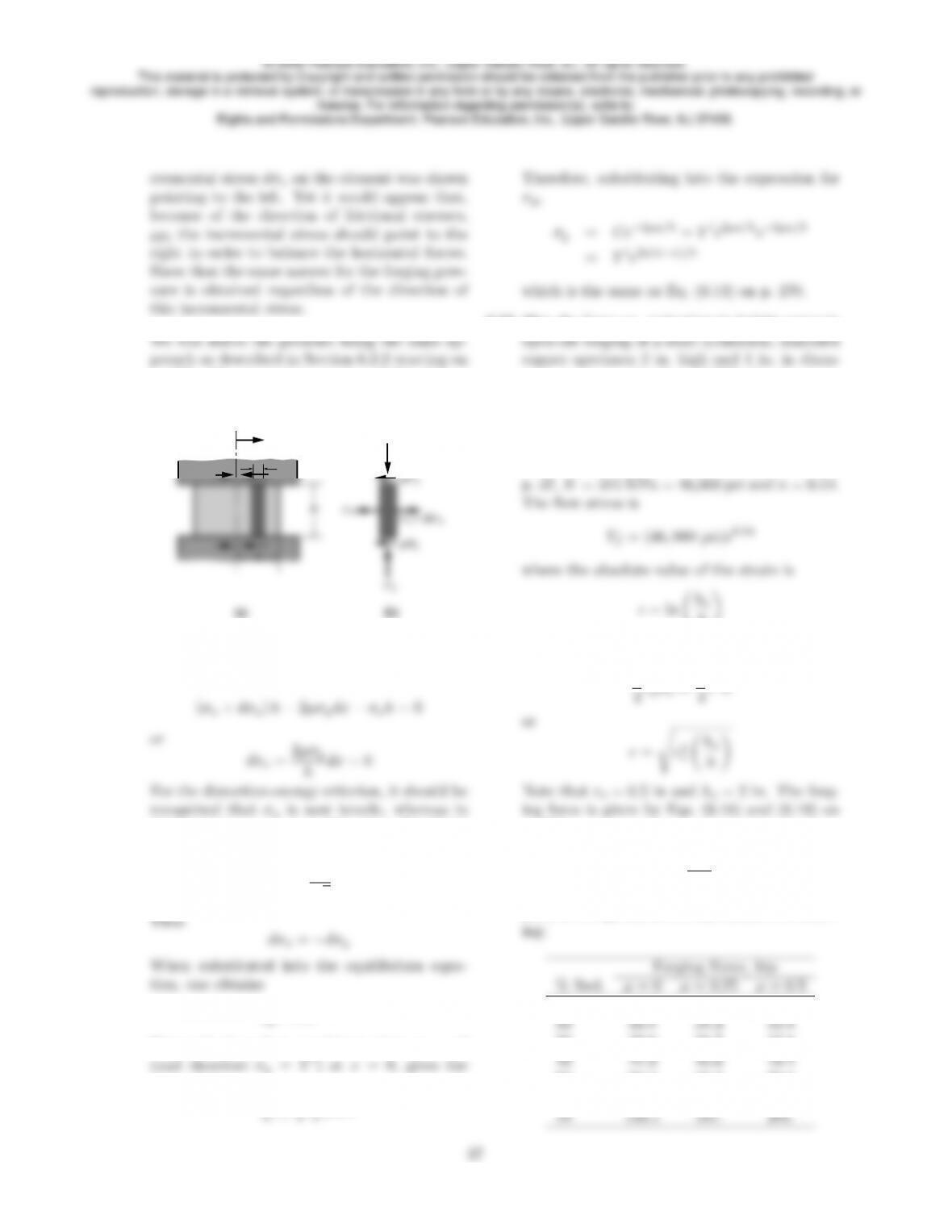
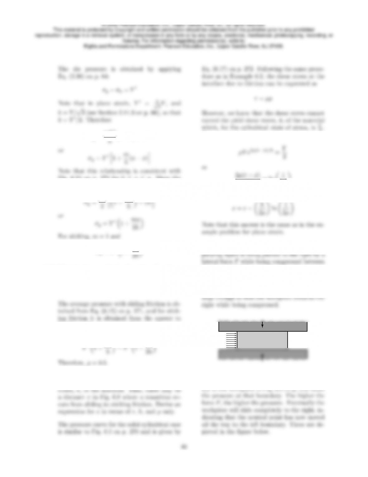
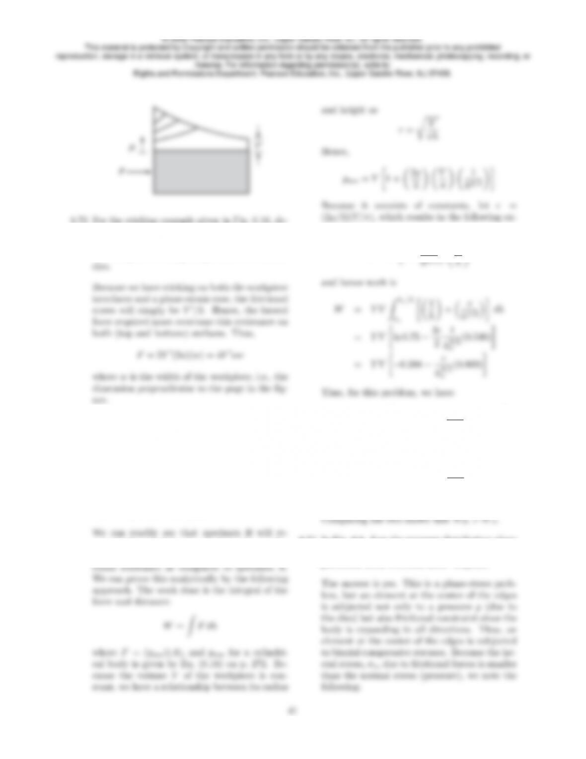
6.71 Assume that the workpiece shown in the accom-
flat dies. (a) Make a sketch of the die-pressure
distribution for the condition for which Fis not
large enough to slide the workpiece to the right.
(b) Make a similar sketch, except that Fis now
F
Applying a compressive force to the left bound-
© 2008 Pearson Education, Inc., Upper Saddle River, NJ. All rights reserved.
This material is protected by Copyright and written permission should be obtained from the publisher prior to any prohibited
reproduction, storage in a retrieval system, or transmission in any form or by any means, electronic, mechanical, photocopying, recording, or
likewise. For information regarding permission(s), write to:
Rights and Permissions Department, Pearson Education, Inc., Upper Saddle River, NJ 07458.
Y’
F
p
6.72 For the sticking example given in Fig. 6.10, de-
rive an expression for the lateral force Fre-
quired to slide the workpiece to the right while
the workpiece is being compressed between flat
6.73 Two solid cylindrical specimens, Aand B, both
made of a perfectly-plastic material, are being
forged with friction and isothermally at room
temperature to a reduction in height of 25%.
Originally, specimen Ahas a height of 2 in. and
a cross-sectional area of 1 in2, and specimen B
has a height of is 1 in. and a cross-sectional area
of 2 in2. Will the work done be the same for
the two specimens? Explain.
quire higher work because it has a larger die-
workpiece surface area, hence a higher fric-
tional resistance as compared to specimen A.
We can prove this analytically by the following
and height as
r=rV
πh
Hence,
pave =Y1 + 2µ
3V
π 1
h3/2
Because it consists of constants, let c=
(2µ/3)(V/π), which results in the following ex-
pression:
F=Y1 + c
WA=Y V −0.288 −c1
23/2(0.809)
=Y V (−0.288 −0.286c)
WB=Y V −0.288 −c1
13/2(0.809)
=Y V (−0.288 −0.809c)
6.74 In Fig. 6.6, does the pressure distribution along
the four edges of the workpiece depend on the
particular yield criterion used? Explain.
© 2008 Pearson Education, Inc., Upper Saddle River, NJ. All rights reserved.
This material is protected by Copyright and written permission should be obtained from the publisher prior to any prohibited
reproduction, storage in a retrieval system, or transmission in any form or by any means, electronic, mechanical, photocopying, recording, or
likewise. For information regarding permission(s), write to:
Rights and Permissions Department, Pearson Education, Inc., Upper Saddle River, NJ 07458.
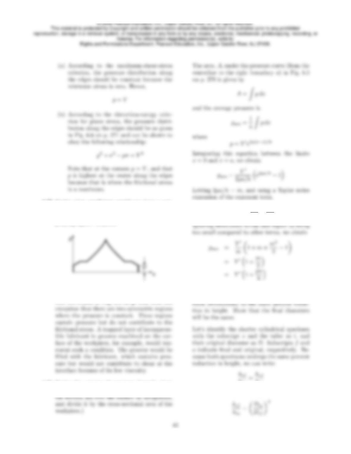
6.75 Under what conditions would you have a nor-
mal pressure distribution in forging a solid
cylindrical workpiece as shown in the accom-
panying figure? Explain.
The pressure distribution is similar to the fric-
tion hill shown in Fig. 6.5 on p. 270, with the
6.76 Derive the average die-pressure formula given
by Eq. (6.15). (Hint: Obtain the volume under
the friction hill over the surface by integration,
expansion of the exponent term,
em= 1 + m+m2
2! +m3
3! +. . .
6.77 Take two solid cylindrical specimens of equal
diameter but different heights, and compress
hto
hso
and from volume constancy,
© 2008 Pearson Education, Inc., Upper Saddle River, NJ. All rights reserved.
This material is protected by Copyright and written permission should be obtained from the publisher prior to any prohibited
reproduction, storage in a retrieval system, or transmission in any form or by any means, electronic, mechanical, photocopying, recording, or
likewise. For information regarding permission(s), write to:
Rights and Permissions Department, Pearson Education, Inc., Upper Saddle River, NJ 07458.
6.78 A rectangular workpiece has the following orig-
inal dimensions: 2a= 100 mm, h= 30 mm and
average-pressure formulas.
h= (1 −0.2)(30) = 24 mm = 0.024 m
Since volume constancy has to be maintained
Thus, a= 62.5 mm = 0.0625 m. The absolute
value of the true strain is
(1.15)(255) = 293 MPa. Thus, from Eq. (6.13)
on p. 270 the pressure as a function of distance
= (293 MPa)e1.042−16.7x
x= 0.0625, which gives the force per unit width
given by Eq. (6.16) on p. 271, the answer will
be
= 1.11 MN
The discrepancy is due to the fact that in de-
6.79 Assume that in upsetting a solid cylindrical
specimen between two flat dies with friction,
the dies are rotated at opposite directions to
each other. How, if at all, will the forging force
change from that for nonrotating dies? (Hint:
Fig. 6.8b on p. 272, we first note that the fric-
tional stresses at the die-specimen interfaces
additional work has to be done in supplying
6.80 A solid cylindrical specimen, made of a per-
hammer is at a maximum when it first con-
© 2008 Pearson Education, Inc., Upper Saddle River, NJ. All rights reserved.
This material is protected by Copyright and written permission should be obtained from the publisher prior to any prohibited
reproduction, storage in a retrieval system, or transmission in any form or by any means, electronic, mechanical, photocopying, recording, or
likewise. For information regarding permission(s), write to:
Rights and Permissions Department, Pearson Education, Inc., Upper Saddle River, NJ 07458.