SOLUTIONS TO SELECTED EXERCISES IN CHAPTER 4
4
4.
.1
1
E
Ex
xp
pl
la
ai
in
n
t
th
he
e
d
di
if
ff
fe
er
re
en
nc
ce
e
b
be
et
tw
we
ee
en
n
a
a
f
fr
ro
om
m–
–t
to
o
c
ch
ha
ar
rt
t
a
an
nd
d
a
a
r
re
el
la
at
ti
io
on
ns
sh
hi
ip
p
c
ch
ha
ar
rt
t,
,
i
in
nd
di
ic
ca
at
ti
in
ng
g
w
wh
he
en
n
e
ea
ac
ch
h
c
ch
ha
ar
rt
t
i
is
s
m
mo
or
re
e
s
su
ui
it
ta
ab
bl
le
e.
.
S
So
ol
lu
ut
ti
io
on
n:
:
• Suitability: The from-to-chart is mostly used when there is a high volume (movement) of
4
4.
.2
2
A
As
ss
su
um
me
e
t
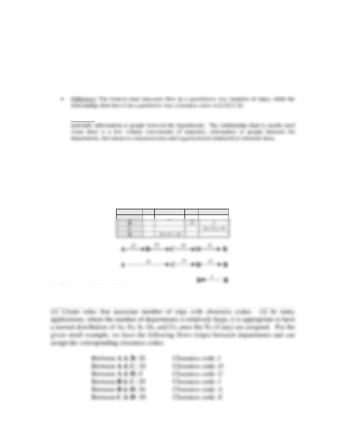
three products are made in four departments A, B, C, and D. Product 1 has a
production volume of 20 pallets per week in the sequence ABCDB. Product 2 has 10
pallets per week in sequence ACDB. Product 3 has 4 pallets per week in sequence BD.
Solution:
(a) Construct from-to-chart.
From\To A B C D
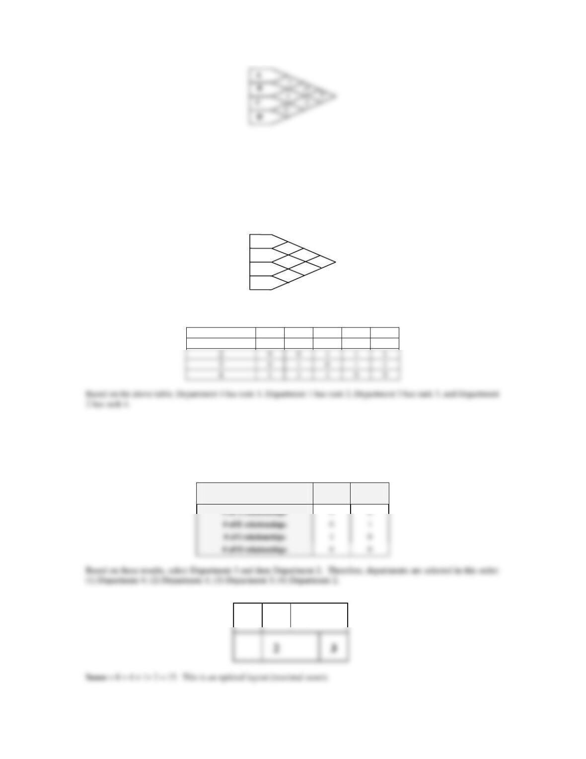
(b) Construct relationship chart.
A general procedure can be as follows: (1) Calculate flows (trips) between departments.
4
4.
.3
3
S
Se
ee
e
s
so
ol
lu
ut
ti
io
on
n
t
to
o
E
Ex
xe
er
rc
ci
is
se
e
3
3.
.1
13
3.
.
4
4.
.4
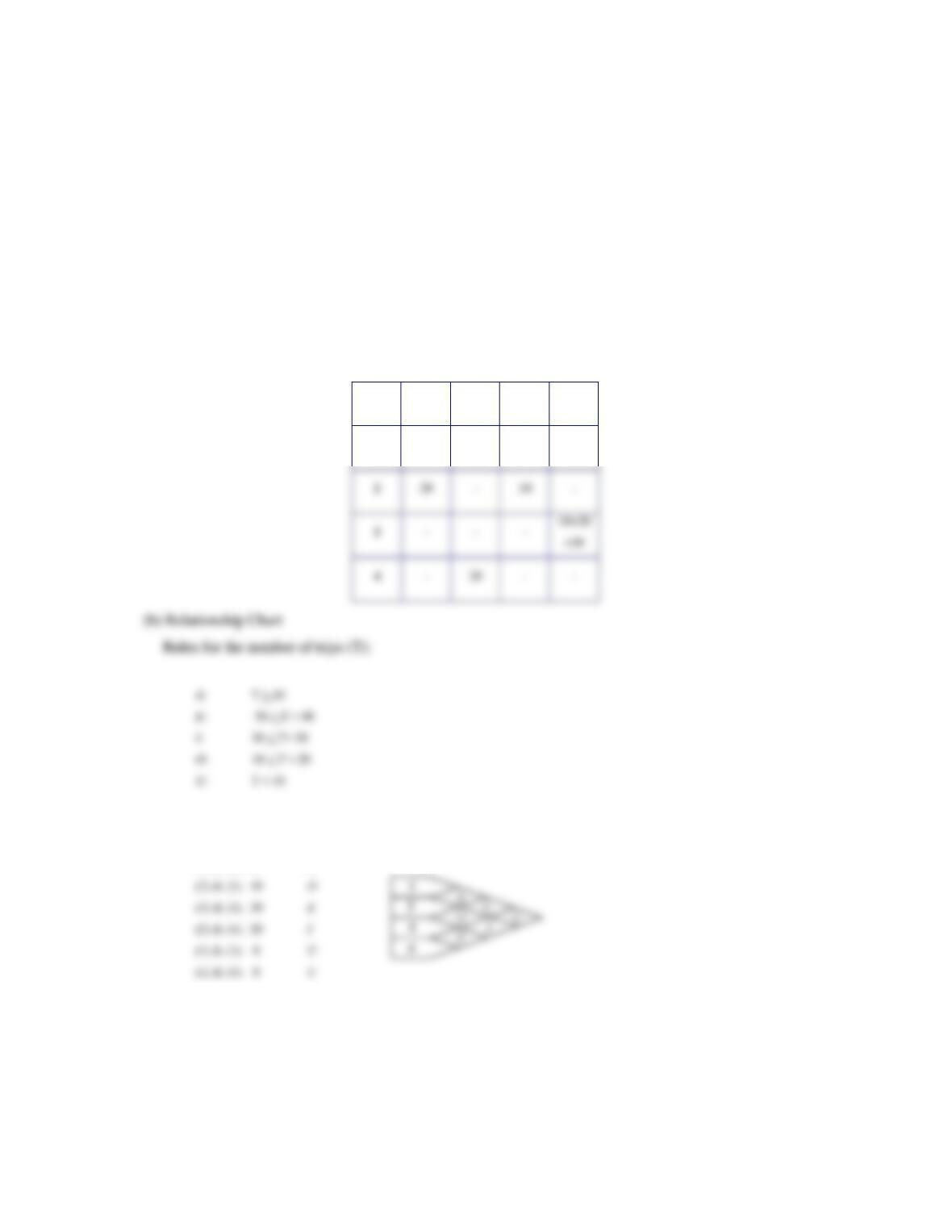
4 Given the following relationship chart, determine the closeness rank, selection order,
and a layout with maximum score (A=8,E=4,I=2,O=1,U=0). Department 1 = 100,
Department 2 = 300, Department 3 = 100, Department 4 = 300. Each department has a
rectangular shape. The total area available is a 20 x 40 rectangle.
Solution
Closeness Ranks
Selection Order
S
Se
el
le
ec
ct
t
D
De
ep
pa
ar
rt
tm
me
en
nt
t
4
4
f
fi
ir
rs
st
t.
.
T
Th
he
en
n
s
se
el
le
ec
ct
t
D
De
ep
pa
ar
rt
tm
me
en
nt
t
1
1
b
be
ec
ca
au
us
se
e
t
th
hi
is
s
o
on
ne
e
h
ha
as
s
a
an
n
A
A–
–r
re
el
la
at
ti
io
on
ns
sh
hi
ip
p
w
wi
it
th
h
D
De
ep
pa
ar
rt
tm
me
en
nt
t
4
4.
.
N
No
ow
w
l
le
et
t
u
us
s
l
lo
oo
ok
k
a
at
t
t
th
he
e
r
re
el
la
at
ti
io
on
ns
sh
hi
ip
ps
s
o
of
f
t
th
he
e
o
ot
th
he
er
r
d
de
ep
pa
ar
rt
tm
me
en
nt
ts
s
w
wi
it
th
h
t
th
ho
os
se
e
a
al
lr
re
ea
ad
dy
y
s
se
el
le
ec
ct
te
ed
d.
.
R
Re
el
la
at
ti
io
on
ns
sh
hi
ip
p
w
wi
it
th
h
d
de
ep
pa
ar
rt
tm
me
en
nt
ts
s
a
al
lr
re
ea
ad
dy
y
s
se
el
le
ec
ct
te
ed
d
(
(1
1
a
an
nd
d
4
4)
)
D
De
ep
pt
t.
.
2
2
D
De
ep
pt
t.
.
3
3
Proposed Layout
Department A E I O U
1 1 0 0 0 2
1
4
1
2
3
4
U
O
E
U
I
A
E
A
4
4.
.5
5
A
A
f
fa
ac
ct
to
or
ry
y
h
ha
as
s
4
4
p
pl
la
an
nn
ni
in
ng
g
d
de
ep
pa
ar
rt
tm
me
en
nt
ts
s
(
(1
1,
,2
2,
,3
3,
,4
4)
).
.
P
Pr
ro
od
du
uc
ct
t
A
A
i
is
s
m
ma
an
nu
uf
fa
ac
ct
tu
ur
re
ed
d
a
ac
cc
co
or
rd
di
in
ng
g
t
to
o
t
th
he
e
s
se
eq
qu
ue
en
nc
ce
e
1
1–
–2
2–
–3
3–
–4
4
a
an
nd
d
p
pr
ro
od
du
uc
ct
t
2
2
a
ac
cc
co
or
rd
di
in
ng
g
t
to
o
t
th
he
e
s
se
eq
qu
ue
en
nc
ce
e
3
3–
–4
4–
–2
2–
–1
1–
–2
2.
.
T
Th
he
e
d
da
ai
il
ly
y
p
pr
ro
od
du
uc
ct
ti
io
on
n
v
vo
ol
lu
um
me
es
s
o
of
f
p
pr
ro
od
du
uc
ct
ts
s
A
A
a
an
nd
d
B
B
a
ar
re
e
1
10
0
a
an
nd
d
2
20
0
p
pa
ar
rt
ts
s,
,
r
re
es
sp
pe
ec
ct
ti
iv
ve
el
ly
y.
.
(
(a
a)
)
C
Co
on
ns
st
tr
ru
uc
ct
t
t
th
he
e
f
fr
ro
om
m–
–t
to
o–
–c
ch
ha
ar
rt
t
i
in
nd
di
ic
ca
at
ti
in
ng
g
t
th
he
e
n
nu
um
mb
be
er
r
o
of
f
t
tr
ri
ip
ps
s
f
fr
ro
om
m
o
on
ne
e
d
de
ep
pa
ar
rt
tm
me
en
nt
t
t
to
o
a
an
no
ot
th
he
er
r.
.
(
(b
b)
)
D
De
ev
ve
el
lo
op
p
a
a
r
re
el
la
at
ti
io
on
ns
sh
hi
ip
p
c
ch
ha
ar
rt
t
f
fo
ol
ll
lo
ow
wi
in
ng
g
t
th
he
es
se
e
r
ru
ul
le
es
s:
:
“
“A
A”
”
f
fo
or
r
a
an
ny
y
t
tw
wo
o
d
de
ep
pa
ar
rt
tm
me
en
nt
ts
s
w
wi
it
th
h
a
a
t
to
ot
ta
al
l
n
nu
um
mb
be
er
r
o
of
f
t
tr
ri
ip
ps
s
(
(i
in
nc
cl
lu
ud
di
in
ng
g
b
bo
ot
th
h
d
di
ir
re
ec
ct
ti
io
on
ns
s)
)
e
eq
qu
ua
al
l
t
to
o
4
40
0
o
or
r
m
mo
or
re
e,
,
“
“E
E”
”
f
fo
or
r
3
30
0
o
or
r
m
mo
or
re
e
b
bu
ut
t
l
le
es
ss
s
t
th
ha
an
n
4
40
0;
;
“
“I
I”
”
f
fo
or
r
2
20
0
o
or
r
m
mo
or
re
e
b
bu
ut
t
l
le
es
ss
s
t
th
ha
an
n
3
30
0;
;
“
“O
O”
”
f
fo
or
r
1
10
0
o
or
r
m
mo
or
re
e
b
bu
ut
t
l
le
es
ss
s
t
th
ha
an
n
2
20
0;
;
“
“U
U”
”
f
fo
or
r
l
le
es
ss
s
t
th
ha
an
n
1
10
0.
.
S
Sh
ho
ow
w
a
al
ll
l
y
yo
ou
ur
r
c
ca
al
lc
cu
ul
la
at
ti
io
on
ns
s.
.
S
So
ol
lu
ut
ti
io
on
n:
:
(
(a
a)
)
F
Fr
ro
om
m–
–t
to
o–
–C
Ch
ha
ar
rt
t
C
Ca
al
lc
cu
ul
la
at
ti
io
on
n
o
of
f
n
nu
um
mb
be
er
r
o
of
f
t
tr
ri
ip
ps
s
(
(T
T)
):
:
(1) & (2): 50 A
4
4.
.6
6
D
De
es
sc
cr
ri
ib
be
e
t
th
he
e
s
sp
pa
ac
ce
e
d
de
et
te
er
rm
mi
in
na
at
ti
io
on
n
m
me
et
th
ho
od
ds
s,
,
i
in
nd
di
ic
ca
at
ti
in
ng
g
w
wh
he
en
n
e
ea
ac
ch
h
o
on
ne
e
i
is
s
m
mo
or
re
e
a
ap
pp
pr
ro
op
pr
ri
ia
at
te
e.
.
S
So
ol
lu
ut
ti
io
on
n:
:
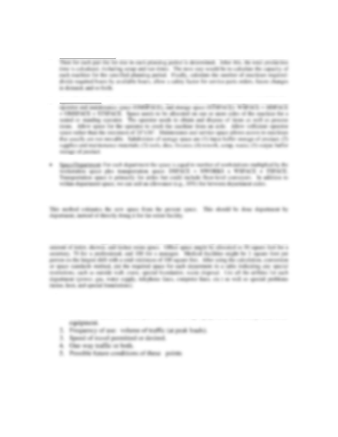
F
Fr
ro
om
m
/
/T
To
o
1
1
2
2
3
3
4
4
1
1
–
–
1
10
0+
+2
20
0
=
=3
30
0
–
–
–
–
A. Calculation Method
• Number of Workstations: Based on the route sheets, all items made by each machine are compiled.
• Space/Workstation: The workstation space is equal to the machine space including travel (MSPACE),
B. Conversion Method
C. Space Standards Method
This method is most appropriate for service and storage areas. Using standards, we can estimate the
4
4.
.7
7
L
Li
is
st
t
t
th
he
e
f
fi
iv
ve
e
m
mo
os
st
t
i
im
mp
po
or
rt
ta
an
nt
t
f
fa
ac
ct
to
or
rs
s
a
af
ff
fe
ec
ct
ti
in
ng
g
a
ai
is
sl
le
e
w
wi
id
dt
th
h.
.
1
1.
.
Use of the aisle: material, personnel, handling equipment, machinery, and other
4
4.
.8
8
Components 1 and 2 have similar handling requirements. Moving 2 units of either
component 1 or 2 is equivalent to moving 1 unit of component 3. The production
volumes for Components 1, 2, 3 are 30, 12, 7, respectively. Moreover, the routing
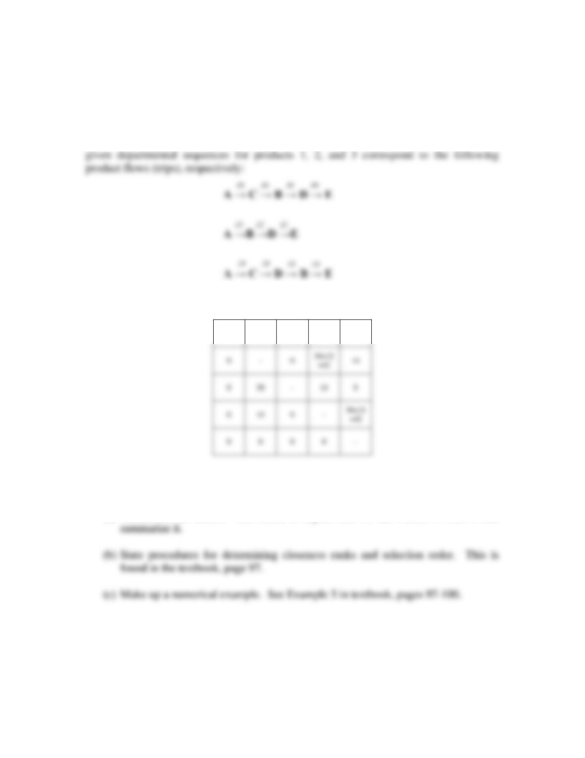
sequences are A-C-B-D-E for 1, A-B-D-E for 2 and A-C-D-B-E for 3. Find a from-to
chart.
Solution:
We use either product 1 or 2 as the reference product to measure number of trips. The
F
Fr
ro
om
m–
–t
to
o
C
Ch
ha
ar
rt
t:
:
–
–
1
12
2
3
30
0+
+1
14
4
=
=
4
44
4
0
0
0
0
4
4.
.9
9
R
Re
ea
ad
d
t
th
he
e
a
ar
rt
ti
ic
cl
le
e
“
“A
A
M
Mi
ic
cr
ro
oc
co
om
mp
pu
ut
te
er
r
P
Pr
ro
og
gr
ra
am
m
t
to
o
A
As
ss
si
is
st
t
i
in
n
P
Pl
la
an
nt
t
L
La
ay
yo
ou
ut
t”
”
[
[4
4]
].
.
(
(a
a)
)
S
Su
um
mm
ma
ar
ri
iz
ze
e
t
th
he
e
a
ar
rt
ti
ic
cl
le
e.
.
T
Th
he
e
a
ar
rt
ti
ic
cl
le
e
i
is
s
c
co
op
pi
ie
ed
d
h
he
er
re
e
f
fo
or
r
t
th
he
e
s
st
tu
ud
de
en
nt
t
t
to
o
r
re
ea
ad
d
i
it
t
a
an
nd
d

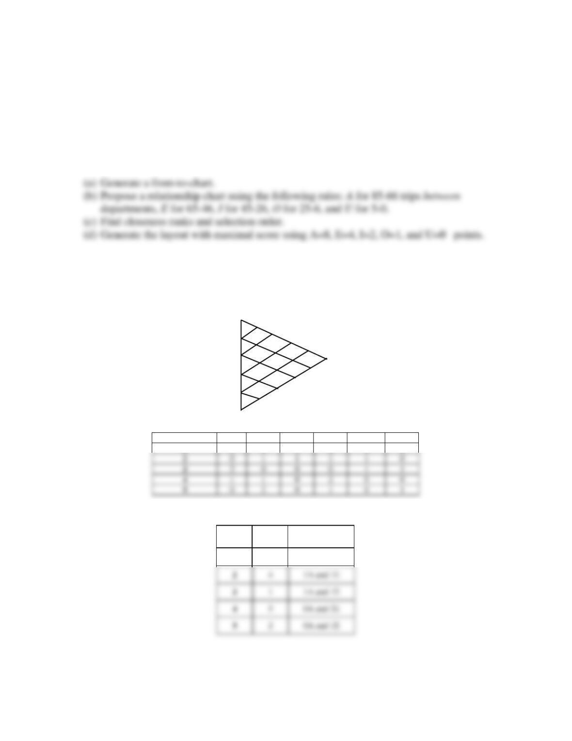
4
4.
.1
10
0 A manufacturing facility consists of five departments 1, 2, 3, 4 and 5. It produces
four components having the manufacturing product routings and production volumes
indicated below:
Component Production Routing Units per Week
1 1-2-3-4-5 20
2 2-3-5-1 25
3 4-5-3 10
4 5-4-3-2-1 30
4.11 Find: (a) closeness rank; (b) selection order; (c) a proposed layout for a
rectangular factory floor (show department locations considering arbitrary departmental
areas) and the score of the layout using A = 8, E = 4, I = 2, O = 1, U = 0, X = -8.
Consider the following relationship chart for a layout consisting of 5 departments:
Solution:
(a) Closeness Rank
Rank Dept. Reason
1 3 2 A’s
Departments #A #E #I #O #U #X
1 1 0 1 2 0 0
1 2
3 4
5
1
2
3
4
5
I A
O
O
U O
E
A X
E
(b) Selection Order
Selection Dept. Reason
# of relations with
Departments 3, 4, 1
Dept.
2
Dept.
5
(c) Proposed Layout
A = 8, E = 4, I = 2, O = 1, U = 0, X = -8
4.12 A manufacturing facility consists of eight departments A, B, C, D, E, F, G, and H.
It produces six components 1, 2, 3, 4, 5, and 6. Production routings and production
volumes are as indicated below:
Component Production Routing Units per Week
1 A-B-G-H 20
2 A-C-D-H 25
3
4