CHAPTER 2
PROCESS SYMBOLS AND DIAGRAMS
OBJECTIVES
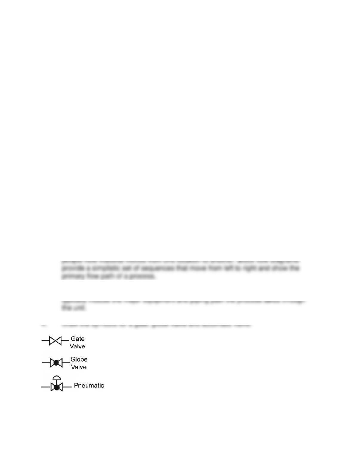
• Draw the symbols used to illustrate process equipment
• Draw the symbols used to illustrate process instruments
• Draw the symbols used to illustrate piping, tubing, etc.
• Describe a block flow diagram
• Draw the symbols used to illustrate electrical symbols
• Draw a process flow drawing PFD.
• Explain the primary differences between PFD’s and piping and instrumentation
drawings P & IDs.
• Describe an equipment location drawing
• Describe an electrical drawing
• Describe an elevation drawing
• Describe the elements of a foundation drawing
• Describe the central functions of a controller.
• Describe instrument blocks, bubbles, process variables, process set points, and
operating percentages.
REVIEW QUESTIONS
1. Describe the purpose of a process schematic. Process schematics are used to
describe the primary flows and equipment used in the facilities.
2. Explain how block flow diagrams can help teach a new technician his or her job.
Simple block flow diagrams can be used to show technical and non-technical
3. Describe the basic elements of a process flow diagram. Process flow diagrams
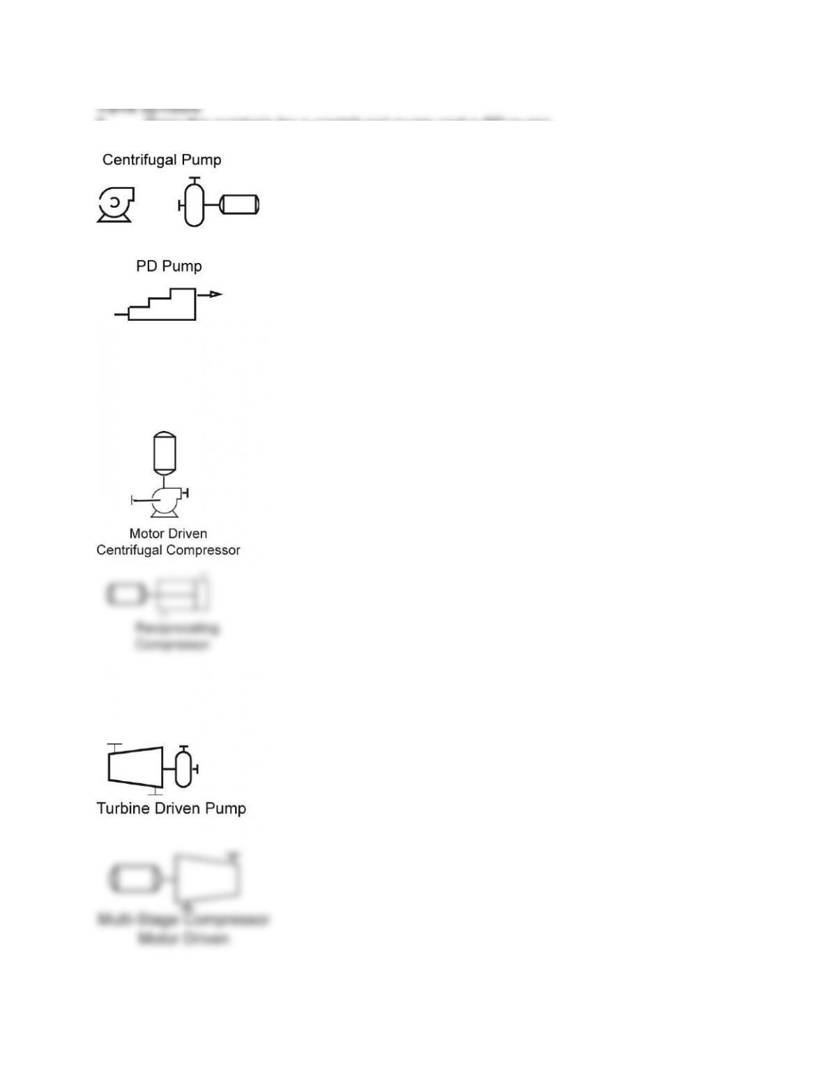
5. Draw the symbols for a centrifugal pump and a PD pump.
Pump symbols
6. Draw the symbols for a blower and a reciprocating compressor.
Compressor symbols
7. Draw the symbols for a steam turbine and centrifugal compressor.
Steam turbine and multi-stage compressor
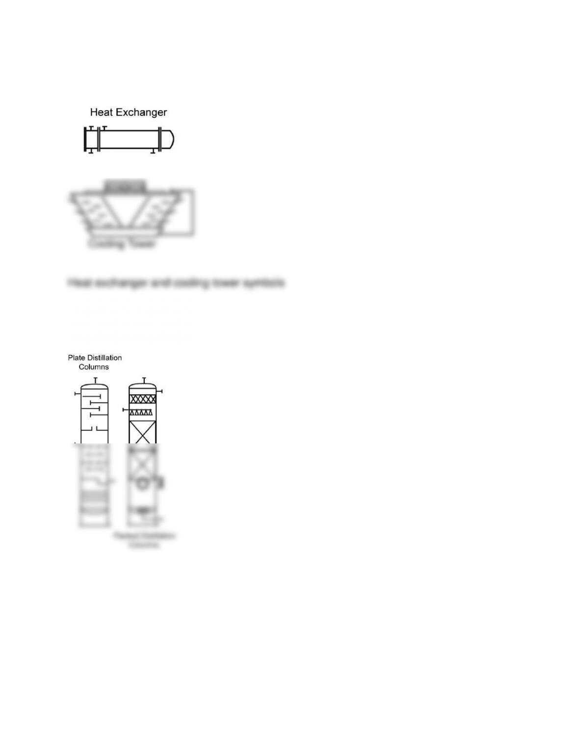
8. Draw the symbols for a heat exchanger and cooling tower.
9. Draw the symbols for a packed and plate column.
Plate and packed columns
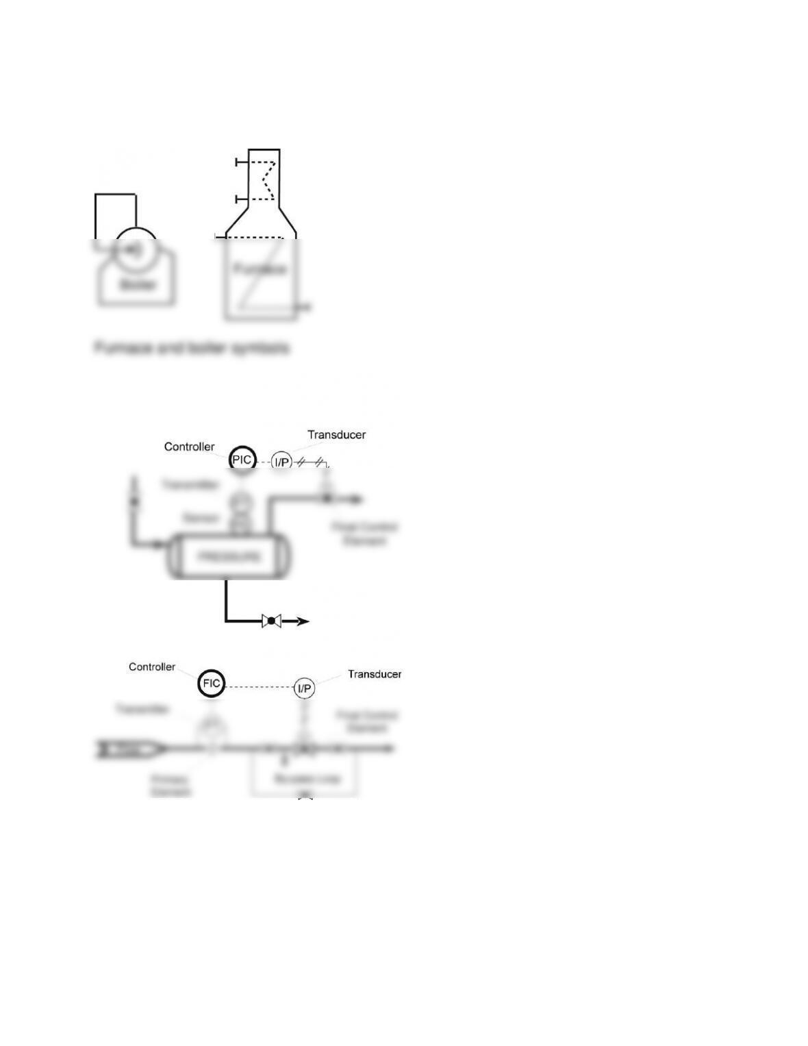
10. Draw the symbols for a furnace and boiler.
11. Draw a pressure and flow control loop.
Pressure and flow control
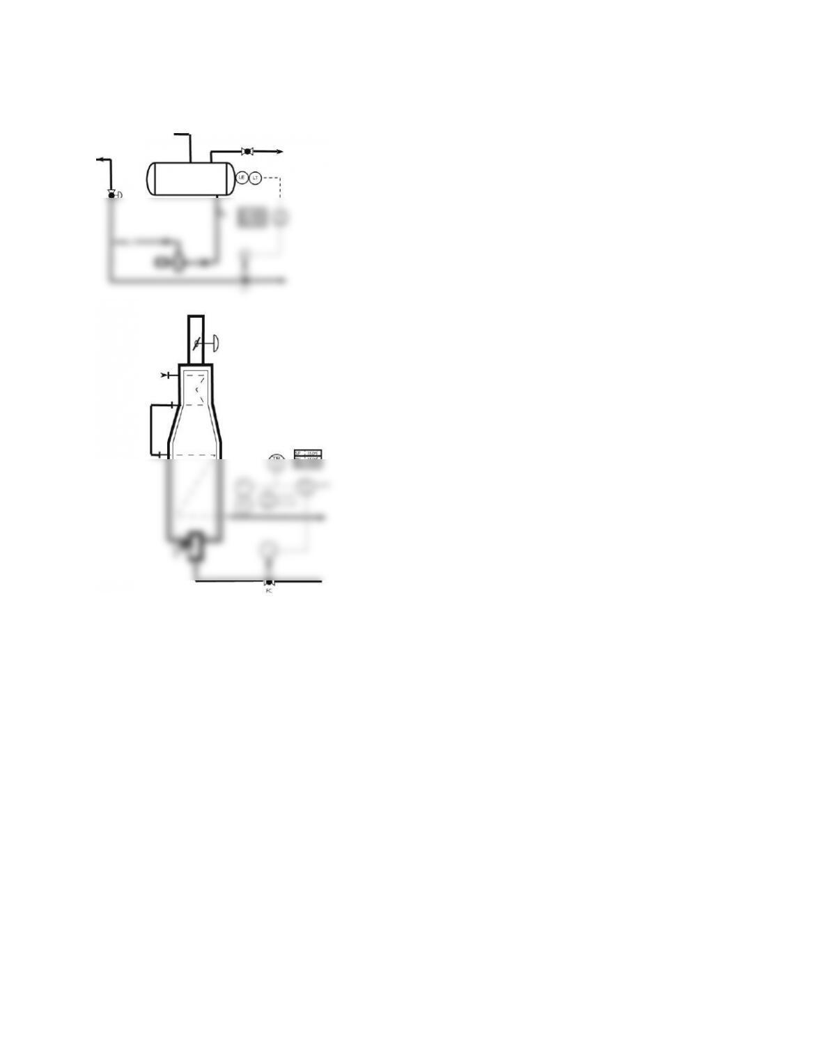
12. Draw a level and temperature control loop.
Level and temperature control
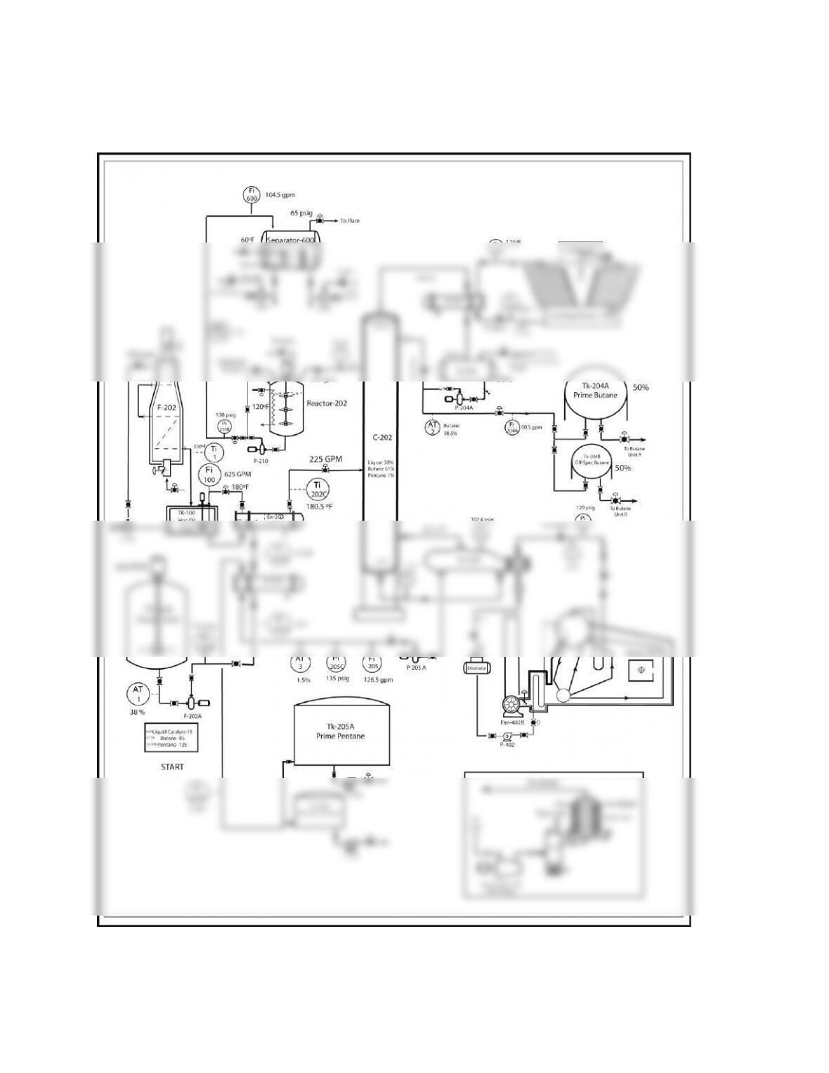
13. Draw a simple process flow diagram using the symbols from the previous
questions.
Multi-variable Plant
14. What information is obtained from a loop diagram?
15. What information is available on electrical one-line diagrams?
16. What information is contained on plot plan drawing?
17. Describe the basic elements of a piping and instrumentation drawing.
A piping and instrumentation drawing is a complete representation of the process
and facilities. The P & ID includes a graphical illustration of the piping,
18. Explain how process instruments are illustrated on a drawing.
Circles or bubbles are used to indicate an instrument. The information inside
the circle identifies the instrument, what it does, and the variable being measured. A
19. List the different types of piping and auxiliary equipment.
Each plant will have a standardized file for their piping and auxiliary
symbols. Process technicians should carefully review the piping symbols for
20. List the different types of tanks.
Open top tank, dome roof tank, cone roof tank, internal and external floating roof
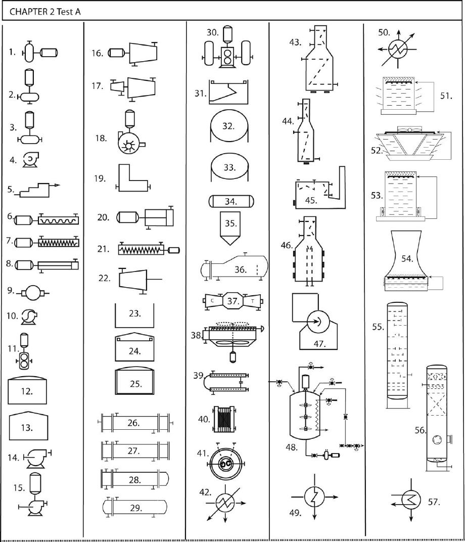
NAME:____________________________ TEST A
DATE:____________________________
CHAPTER TWO
TEST PROCESS SYMBOLS AND DIAGRAMS
Symbols and Diagrams 1
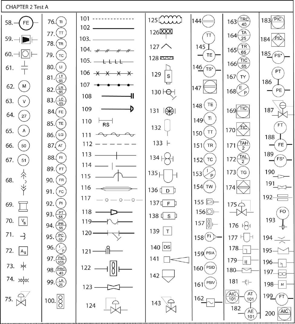
Symbols and Diagrams 2
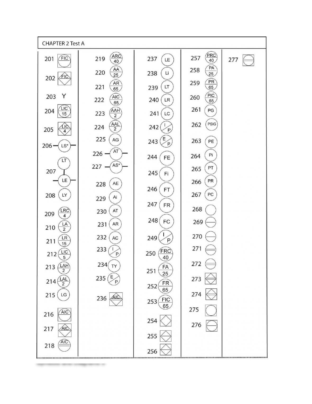
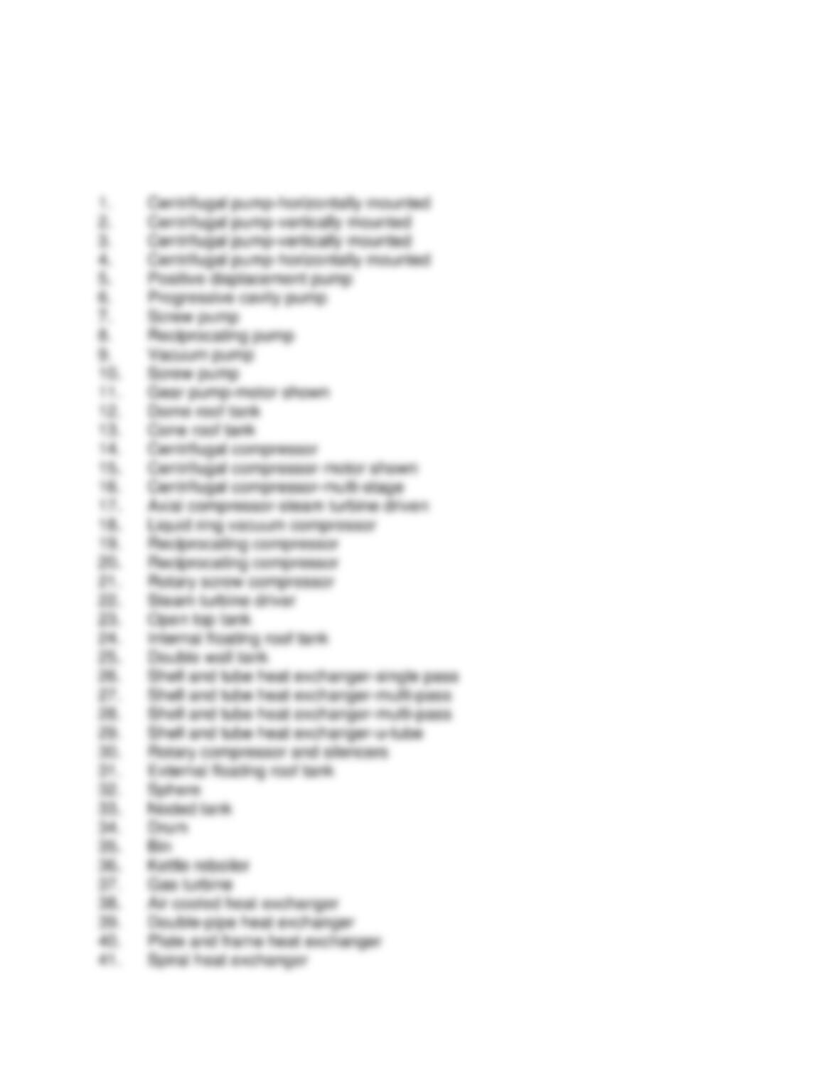
Chapter 2
Process Symbols and Diagrams
Answer Key
180. Wedge meter
181. Orifice plate
182. Analytical indicating controller- DCS, shows inline element
183. Pressure indicating controller- DCS
184. Pressure indicating controller- PLC
225. Analytical gauge
227. Analytical switch- high/low
229. Analytical indicator
231. Analytical recorder
233. Transducer or converter
235. Transducer or converter- electric to pneumatic
237. Level element
239. Level transmitter
241. Level controller
243. transducer or converter, electric to pneumatic
245. Flow indicator
247. Flow recorder
249. transducer or converter
251. Flow alarm
253. Flow indicating controller- remote location
255. PLC Controller- remote location
257. Pressure recording controller- remote location
259. Pressure recorder- remote location
261. Pressure gauge
263. Pressure element
265. Pressure transmitter
267. Pressure controller- field mounted
269. Instrument bubble- remote location

271. Instrument bubble- remote & field, secondary control room
273. PLC controller- remote or field, secondary control room
275. DCS controller- field mounted
277. DCS controller- remote and field, secondary control room