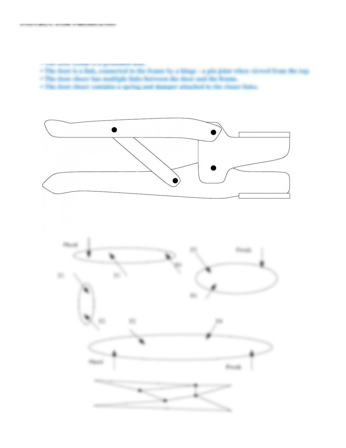
Problem 12.93
Identify joints and members in a standard door with a closing system.
Inst. Ans. 12.93 Assuming it is a large door with an overhead door closer:
Problem 12.94
For the spreading tool pictured here, create free body diagrams and then a stick diagram.
Inst. Ans. 12.94
F2 F4
F4
F3
F3
F1F1
Fhand
Fhand
Fwork
Fwork
F2
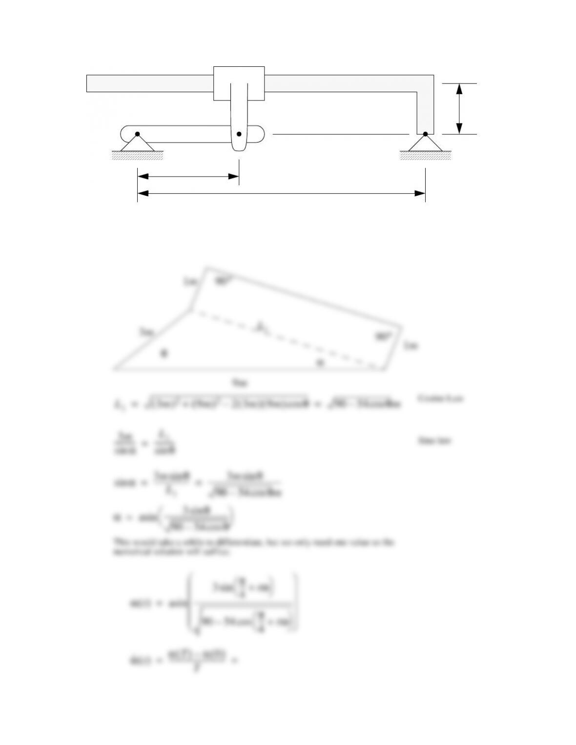
Problem 12.95
12.95 In the diagram shown here, if the crank EA has been rotated 45° counterclockwise about E and has a
rotational velocity of 10 rad/sec, what is the angular velocity of the angled rod BD?
Inst. Ans. 12.95
A
B
D
E
9m
3m
1m
θ
L
1
2
2
α
9m
1m90°
3m90°1m
Cosine Law
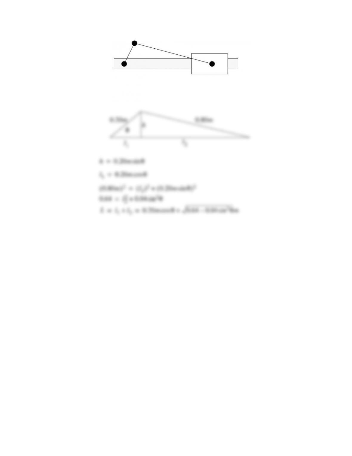
Problem 12.96
In the diagram, the crank is 20 cm long, the driver is 80 cm long, and the crank is rotating at 60 RPM. Draw
a graph of the velocity of the collar. Do calculations as needed.
Inst. Ans. 12.96
0.80m( )
2
l
2
( )
2
0.20mθsin( )
2
+=
h0.20mθsin=
θh
l
1
0.80m0.20m
l
2
l
1
0.20mθcos=
0.64 l
2
2
0.04 θsin
2
+=
L l
1
l
2
+ 0.20mθcos 0.64 0.04 θsin
2
–m+= =
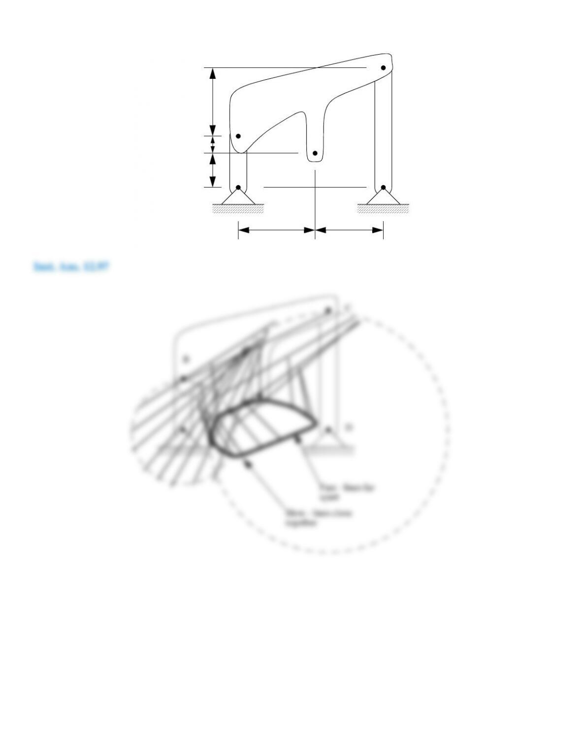
Problem 12.97
Trace the path for point E in the diagram, as the crank is rotated about joint A.
25 cm
5 cm
10 cm
30 cm 25 cm
A
B
C
D
E
A
B
C
D
E
Problem 12.98
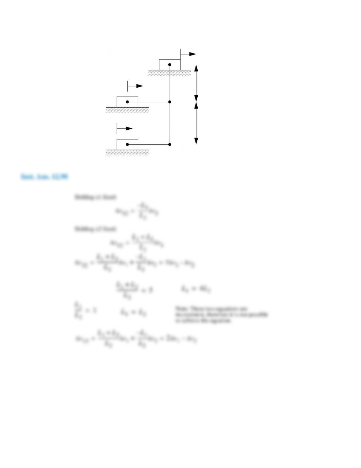
Differential mechanisms allow us to effectively do subtraction or averaging. If we want to determine the
difference between two linear motions we could use a mechanism like the one shown here. Draw a skeleton diagram for
the mechanism, and select L1 and L2 values that would give the ∆ x
12
equation.
∆x1
∆x2
∆x12 5∆x1∆x2
–=
L1
L2
∆x12
L
1
–
L
2
–––––––––
∆x
2
=
Holding x1 fixed:
∆x12
L
1
L
2
+
––––––––––––––––––
∆x
1
=
Holding x2 fixed:
Problem 12.99
Find the position and displacement of a scotch yoke for a speed of 120 RPM and a crank arm length of 1 m.
Inst. Ans. 12.99
Problem 12.100
Relate the position of the yoke to the leftmost crank in the diagram.
Inst. Ans. 12.100
x
roller
x
yoke
1mθcos ωtcos( )m= = =
v
yoke
ω ωsin t( )m
s
––––
=
θ
a
b
ab
x
x a θcos=
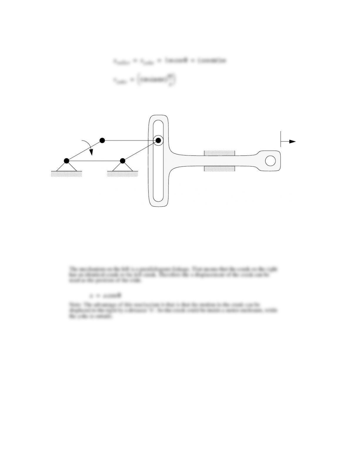
The mechanism on the left is a parallelogram linkage. That means that the crank on the right
has an identical crank to the left crank. Therefore the x displacement of the crank can be
used as the position of the slide.
Note: The advantage of this mechanism is that is that the motion in the crank can be
displaced to the right by a distance ’b’. So the crank could be inside a motor enclosure, while
the yoke is outside.
Problem 12.101
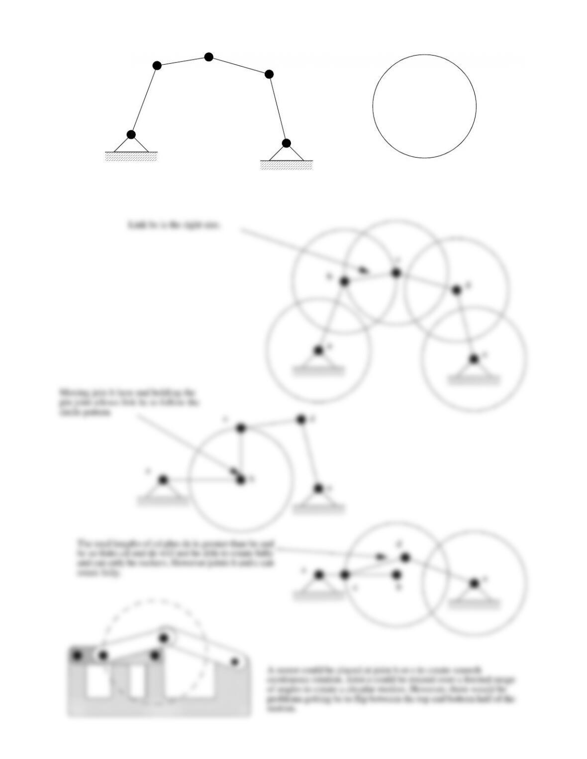
Design a mechanism that would trace the circle using the five links pictured here.
Inst. Ans. 12.101
Link bc is the right size.
c
Problem 12.102
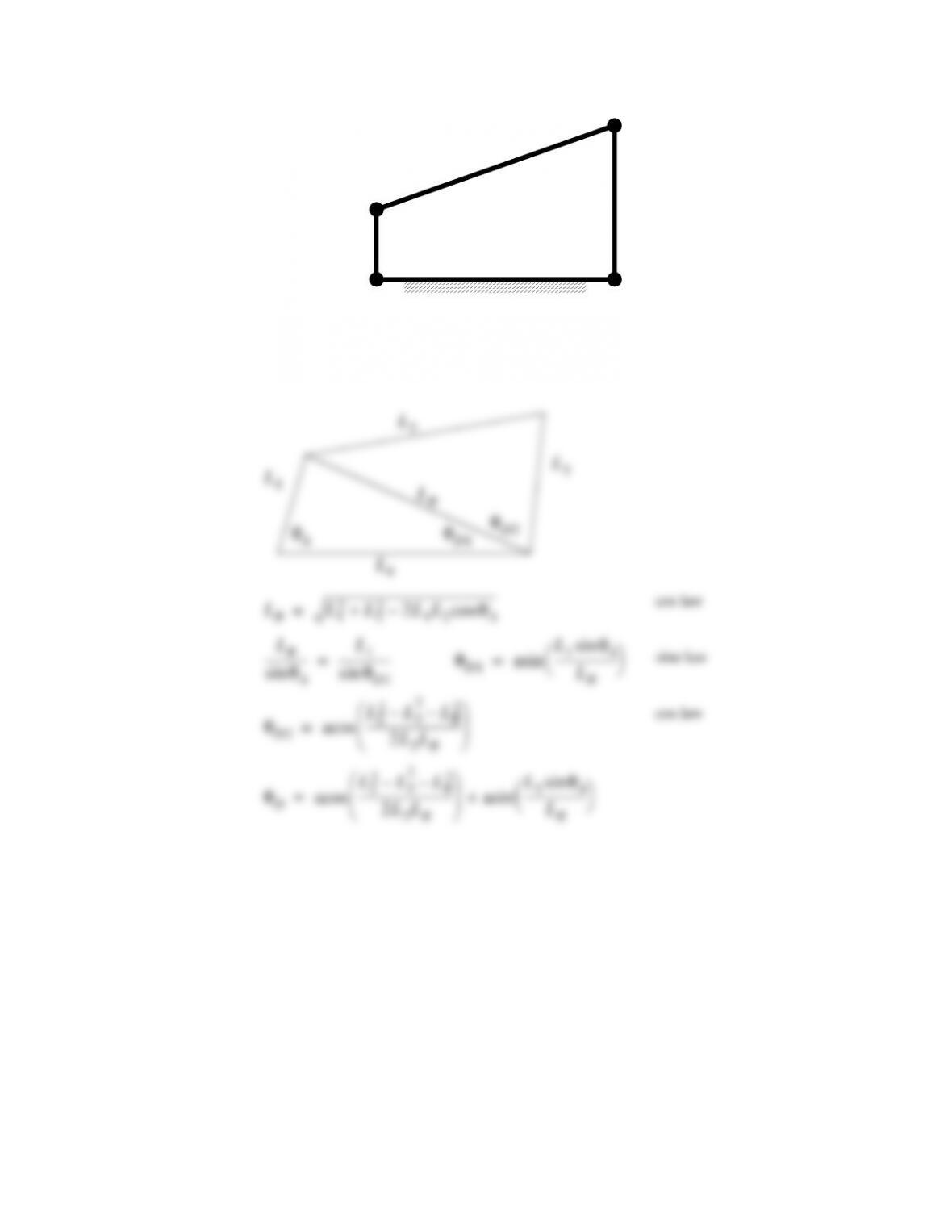
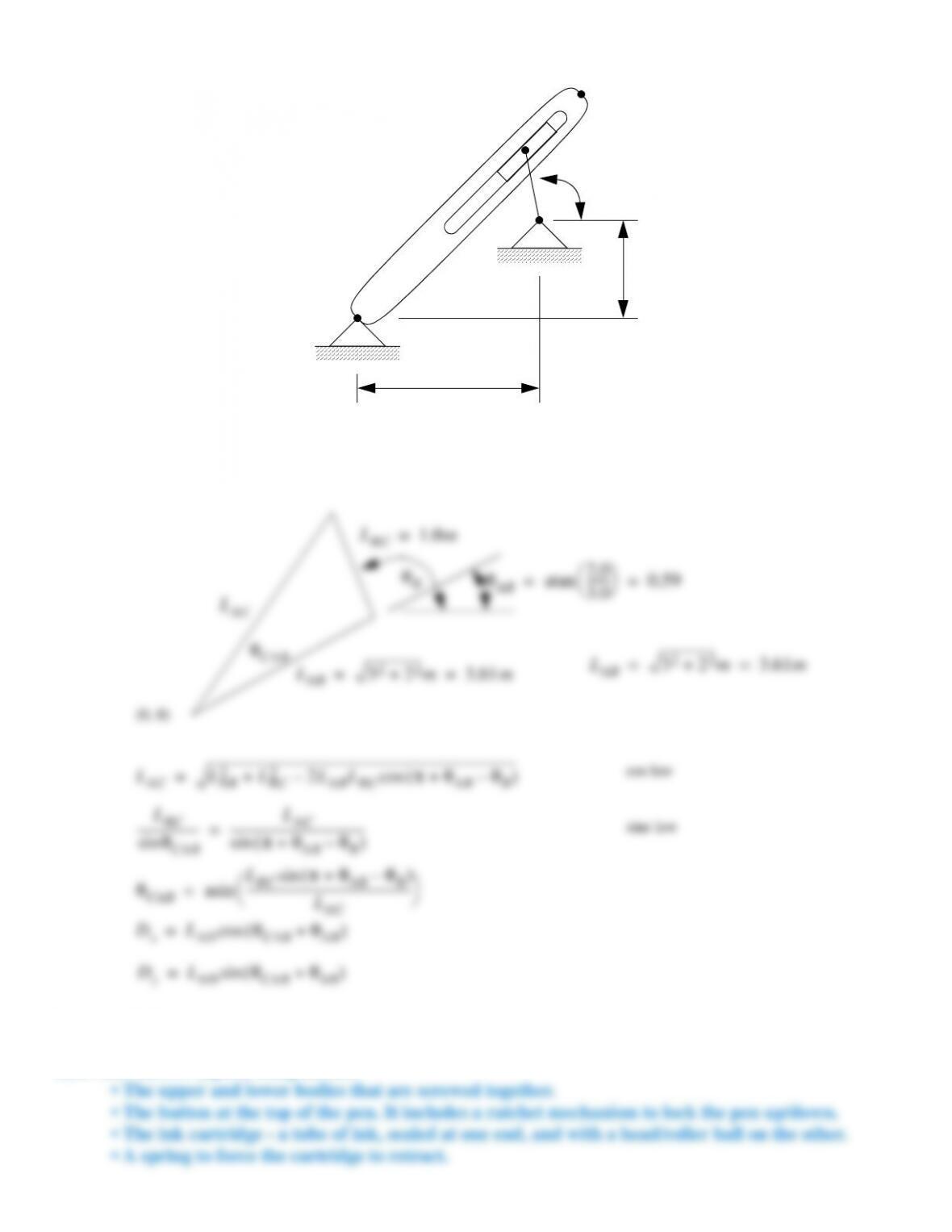
In the diagram shown here, given the crank angle (at A) find the rocker angle (at D). Provide a
trigonometric equation.
Inst. Ans. 12.102
A
B
C
D
L1
L2
L3
L4
θ
A
L
3
L
2
L
1
θ
D2
θ
D1
L
R
L
4
L
R
L
1
2
L
2
2
2L
1
L
2
θ
A
cos–+=
L
R
θ
A
sin
–––––––––––––– L
1
θ
D1
sin
–––––––––––––––––
=θ
D1
L
1
θ
A
sin
L
R
––––––––––––––––––––
asin=
θ
D2
L
2
2
L
3
2
–L
R
2
–
2L
3
L
R
––––––––––––––––––––––––––––––
acos=
θ
D
L
2
2
L
3
2
–L
R
2
–
2L
3
L
R
––––––––––––––––––––––––––––––
acos L
1
θ
A
sin
L
R
––––––––––––––––––––
asin+=
cos law
sine law
cos law
Problem 12.103
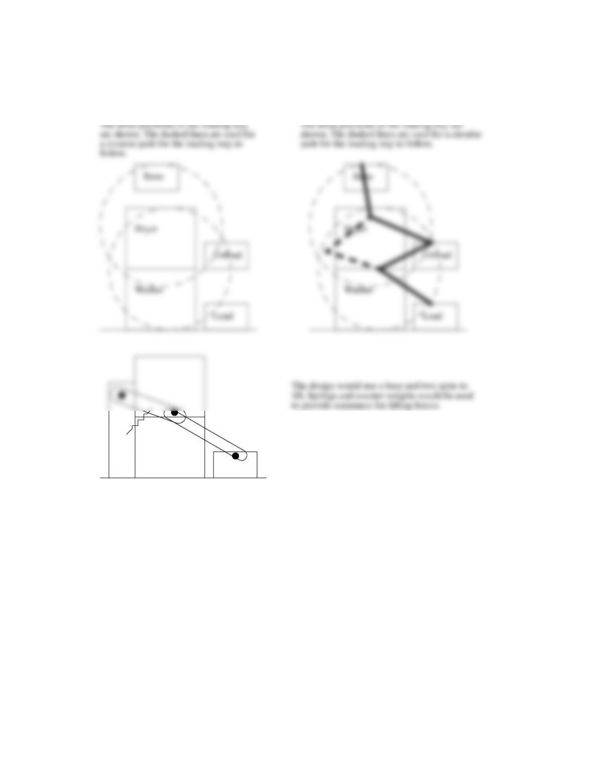
In the diagram, crank CB is 1 m in length. Find the location of point D as a function of the crank angle at B.
Inst. Ans. 12.103
A
B
C
D
3 m
2 m
(0, 0)
sine law
cos law
L
AB
3
2
2
2
+m3.61m= =
L
BC
1.0m=
θ
AB
2.0
3.0
–––––––
atan 0.59= =
θ
B
L
AC
L
AB
2
L
BC
2
2L
AB
L
BC
π θ
AB
θ
B
–+( )cos–+=
L
BC
θ
CAB
sin
–––––––––––––––––––– L
AC
π θ
AB
θ
B
–+( )sin
–––––––––––––––––––––––––––––––––––––––––––
=
L
AB
3
2
2
2
+m3.61m= =
L
AC
θ
CAB
θ
CAB
L
BC
π θ
AB
θ
B
–+( )sin
L
AC
–––––––––––––––––––––––––––––––––––––––––––––––––––––
asin=
D
x
L
AD
θ
CAB
θ
AB
+( )cos=
Problem 12.105
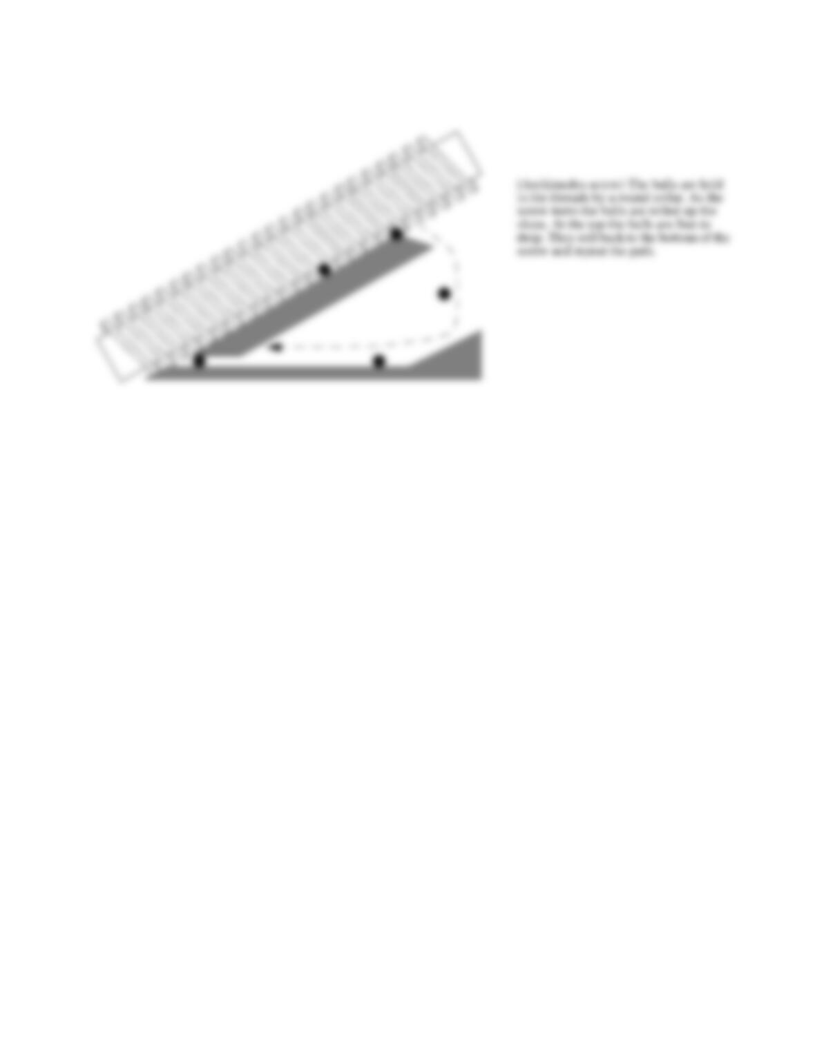
Design a mechanism for a clothes washer and dryer pair where the washer is located below the dryer. The
clothes should be pulled onto a platform at the bottom and then lifted to the dryer on top where they will be pushed
into the dryer. When it is not in use the mechanism should be retracted to the top of the dryer.
Inst. Ans. 12.105
Dryer
Unload
Store
The three positions of the loading tray
are shown. The dashed lines are used for
a circular path for the loading tray to
follow.
The three positions of the loading tray are
shown. The dashed lines are used for a circular
path for the loading tray to follow.
Dryer
Unload
Store
Problem 12.106
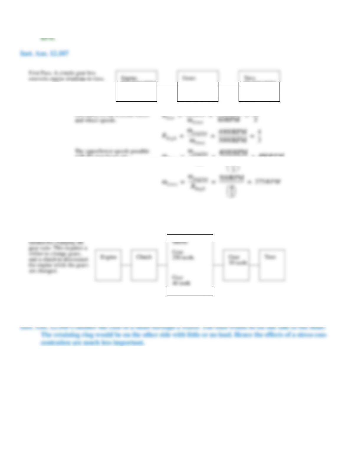
Design a screw-based system to lift balls to a designated height, H , and then drop them.
Inst. Ans. 12.106
(Archimedes screw) The balls are held
in the threads by a round collar. As the
screw turns the balls are rolled up the
slope. At the top the balls are free to
drop. They roll back to the bottom of the
screw and repeat the path.
Problem 12.107
Design a simplified drive system for a vehicle. The system should use an internal combustion engine that
cannot rotate at less than 500 RPM or above 4000 RPM. The system should output speeds between 60 RPM and 3000
Problem 12.108
If a slot weakens a shaft, why are retaining rings popular?
Inst. Ans. 12.108 Consider the case of a shaft through a wheel. The load would be on one side of the shaft.
The retaining ring would be on the other side with little or no load. Hence the effects of a stress con-
centration are much less important.
Tires
60-3000 RPM
GearsEngine
500-4000 RPM
First Pass: A simple gear box
converts engine rotations to tires.
The needed gear ratios are
calculated for the extreme motor
and wheel speeds.
R
low
ω
engine
ω
tires
––––––––––––––––– 500RPM
60RPM
–––––––––––––––––––––– 25
3
––––––
= = =
R
high
ω
engine
ω
tires
––––––––––––––––– 4000RPM
3000RPM
––––––––––––––––––––––––– 4
3
–––
= = =
The upper/lower speeds possible
with the gear boxes are…
ω
tires
ω
engine
R
low
––––––––––––––––– 4000RPM
25
3
––––––
––––––––––––––––––––––––– 480RPM= = =
ω
tires
ω
engine
R
high
––––––––––––––––– 500RPM
4
3
–––
–––––––––––––––––––––– 375RPM= = =
In the low gear ratio the tires can reach a maximum speed of 480RPM. In the high gear ratio the tires can turn as slowly
as 375RPM. Therefore the two gears overlap, but the overlap is narrow. For a better design we could add a third
intermediate gear ratio. For example 14/3 might be a reasonable compromise.
TiresGear
30 teeth.
Engine
Second Pass – A system is
needed for changing the
gear ratio. This requires a
shifter to change gears,
and a clutch to disconnect
Clutch Gear
250 teeth.
Shifter
Problem 12.109
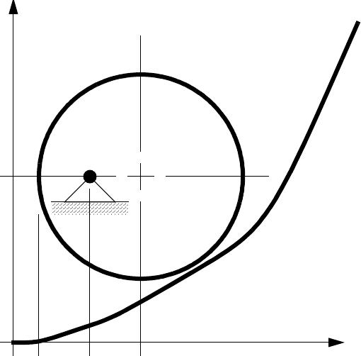
Find the resting position for the disk on the cam surface in the orientation shown.
Inst. Ans. 12.109
y x( ) x
2
–––
sin e0.15x
+=
6
135
y x( ) x
2
–––
sin e0.15x
+=
We begin by finding a center point for the circle based upon a contact point. For any x, there is a point y,
and a slope at that point. If a circle touches that point it would need to be tangent. Therefore the center of
the touching circle would be 4 units away from the tangent.
Problem 12.110
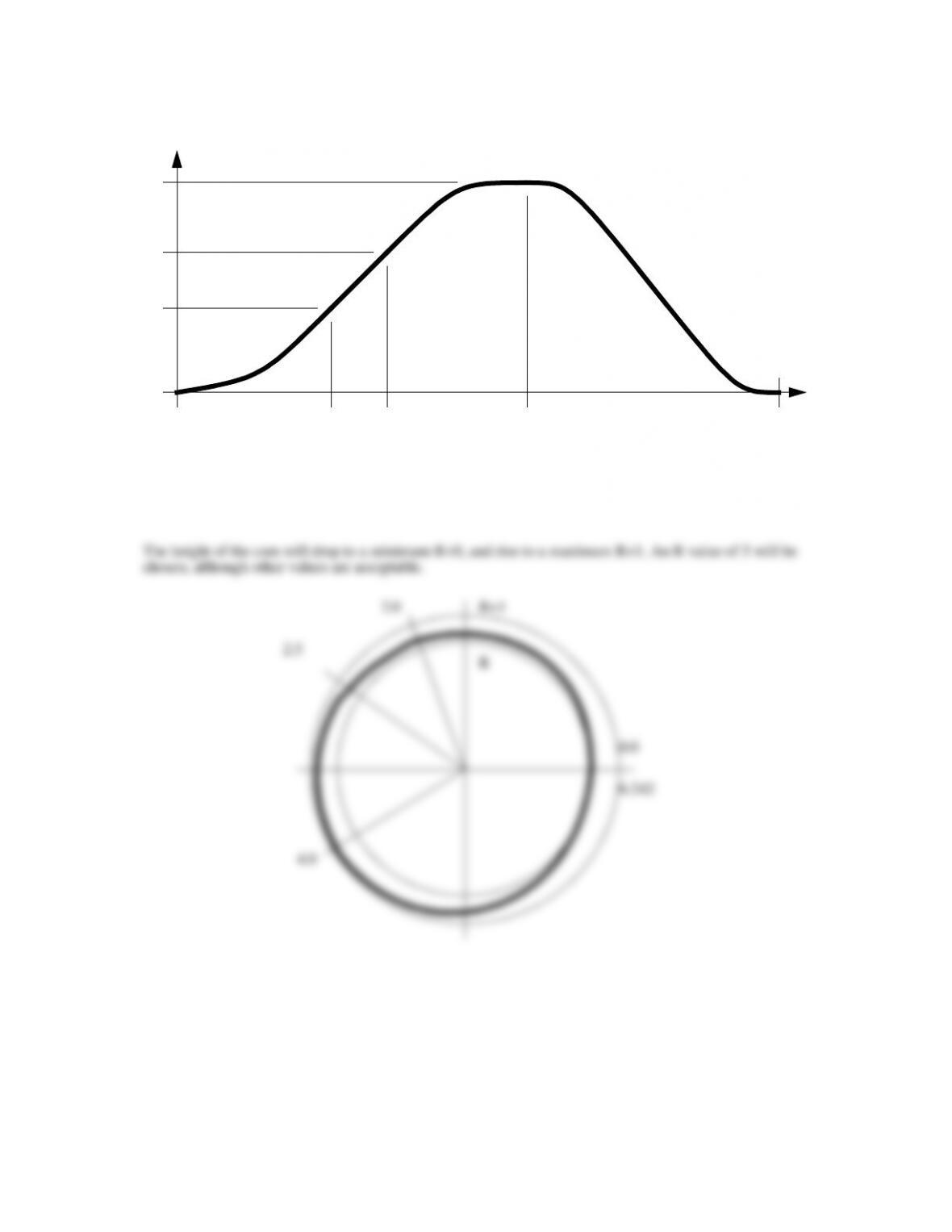
The motion profile curve shown here has 4 segments. Segments A and C are based on polynomials. Segment
D is based on a harmonic/cosine function. Segment B is a constant velocity segment. Create a cam that will produce the
motion profile with a knife-edge follower.
Inst. Ans. 12.110
θ
1.0
0.5
0.3
0.0
0.0 2.0 2.5 4.0 6.242
y
A
B
C
D
The height of the cam will drop to a minimum R+0, and rise to a maximum R+1. An R value of 5 will be
chosen, although other values are acceptable.
2.0
4.0
6.242
R+1
Problem 12.111
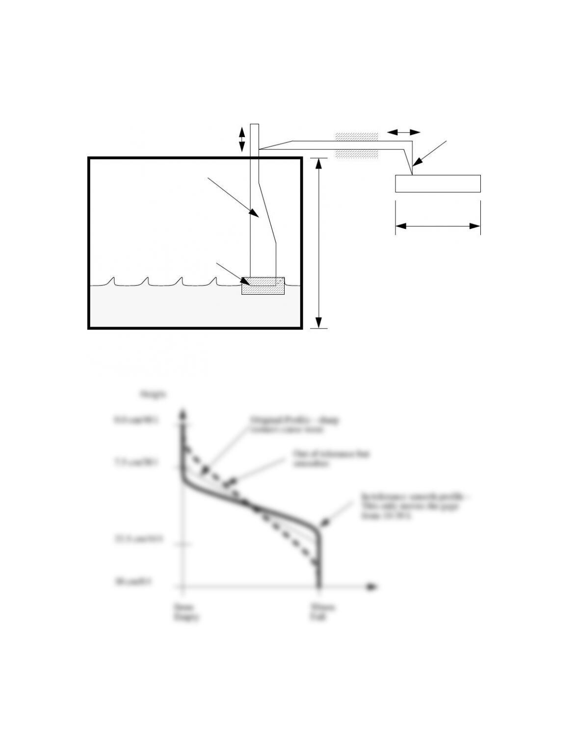
You were recently hired as a fuel containment and monitoring specialist for Generous Motors. Your first job
is to design a mechanical gauge for an instrument panel. The tank holds up to 40 liters of fuel. It has been determined
that the needle on the gauge should remain steady at the full “F” mark while the tank contains 30 to 40 liters. When the
tank has less than 10 liters the gauge should read empty “E.” The last design was a failure, and your boss fired the
engineer responsible. It seems that his design did not follow good cam design rules—the velocity and accelerations were
not minimized—and so the gauge would wear out and jam prematurely. Design a new cam to relate the fl oat in the
tank to the gauge on the instrument panel.
Inst. Ans. 12.111
Gas/petrol tank.
Linear cam.
Float
Follower Needle
pointer.
30 cm
50 mm
E F
Motion
Gauge
0.0 cm/40 l
7.5 cm/30 l
0mm
Empty 50mm
Full
Height
In tolerance smooth profile –
This only moves the gage
from 10-30 l.
Original Profile – sharp
corners cause wear.
Out of tolerance but
smoother.