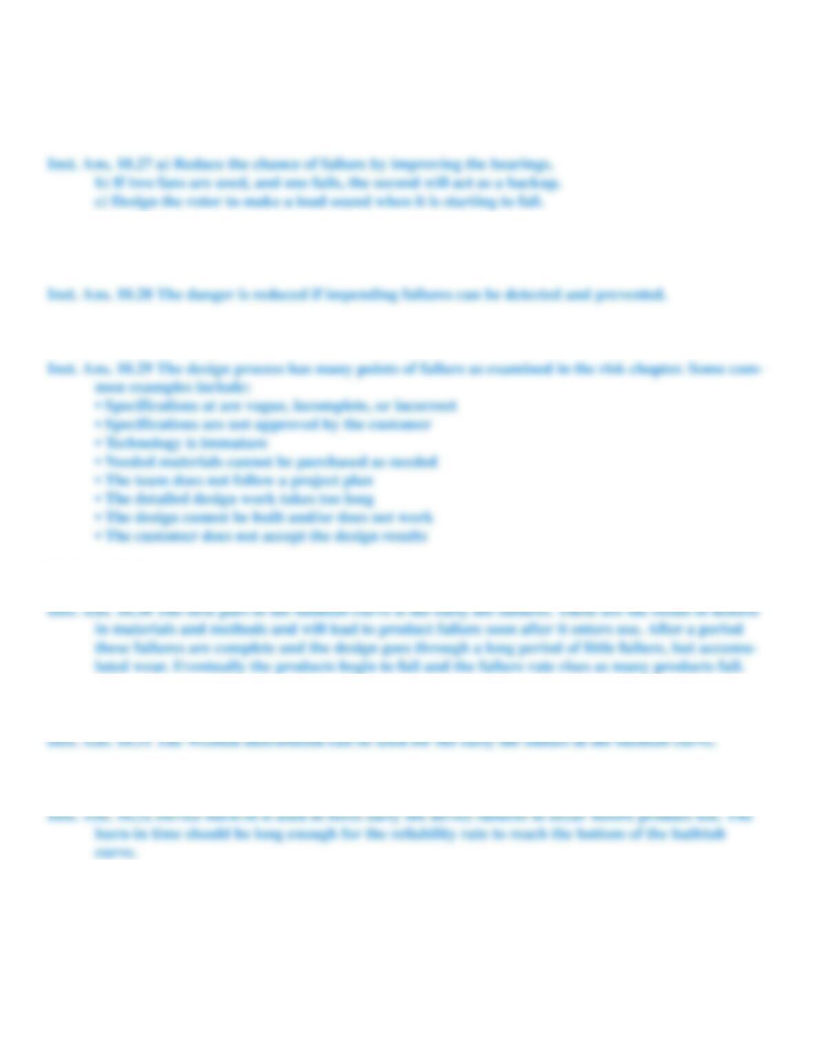
INSTRUCTOR PROBLEMS
Problem 10.27
Fans can be used to control electronics including CPUs. If the fan fails the result could be catastrophic.
Develop options to make the fan safer by (a) reducing the chance of failure, (b) reducing the impact of failure, and (c)
detecting the onset of failure.
Problem 10.28
Sometimes parts will make noise, change color, become loose, or bend before failure. Explain how this reduces
the danger.
Problem 10.29
List common sources of failure in the design process.
Problem 10.30
How does the bathtub curve relate early- and late-life failures?
Problem 10.31
What is the relationship between the bathtub curve and the Weibull distribution?
Problem 10.32
What is the purpose of device “burn in”?
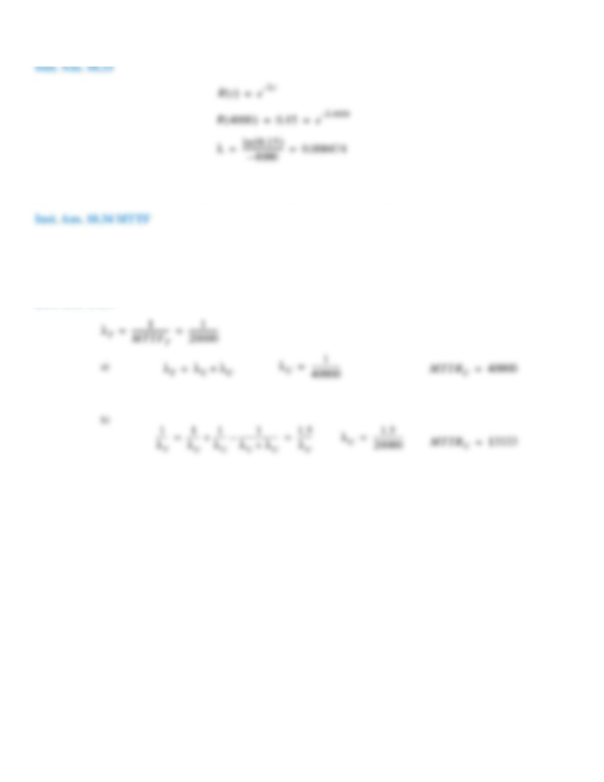
Problem 10.33
What is the failure rate if 15% of all devices are working at 4000 hours.
Problem 10.34
If a unit cannot be repaired would you use MTBF, MTTR, and/or MTTF.
Problem 10.35
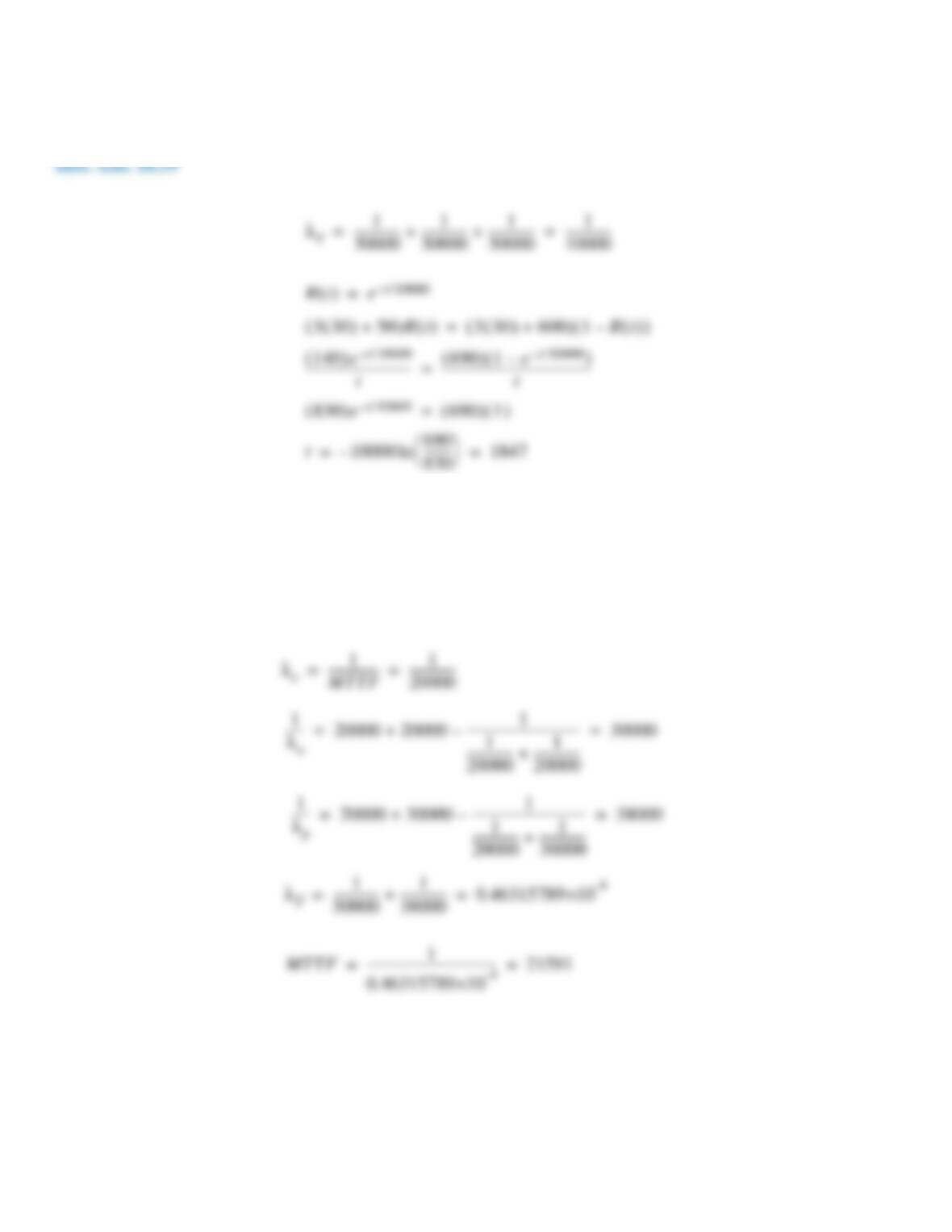
A design must have an MTTF of 20,000 hours.
(a) The device is made with two identical units connected in series. What is the required MTTF for each unit?
(b) The device is made with two identical units connected in parallel. What is the required MTTF for each unit?
Inst. Ans. 10.35
R t( ) e
λt–
=
R4000( ) 0.15 e
λ4000–
= =
λ0.15( )ln 4000–
–––––––––––––––––––– 0.000474= =
λ
T
1
MTTF
T
––––––––––––––––––– 1
20000
–––––––––––––––
= =
λ
U
1
40000
–––––––––––––––
=
a)
λ
T
λ
U
λ
U
+= MTTR
U
40000=
λ
U
1.5
20000
–––––––––––––––
=
b)
1
λ
T
–––––– 1
λ
U
–––––– 1
λ
U
–––––– 1
λ
U
λ
U
+
–––––––––––––––––––
–+ 1.5
λ
U
–––––––
= = MTTR
U
13333=
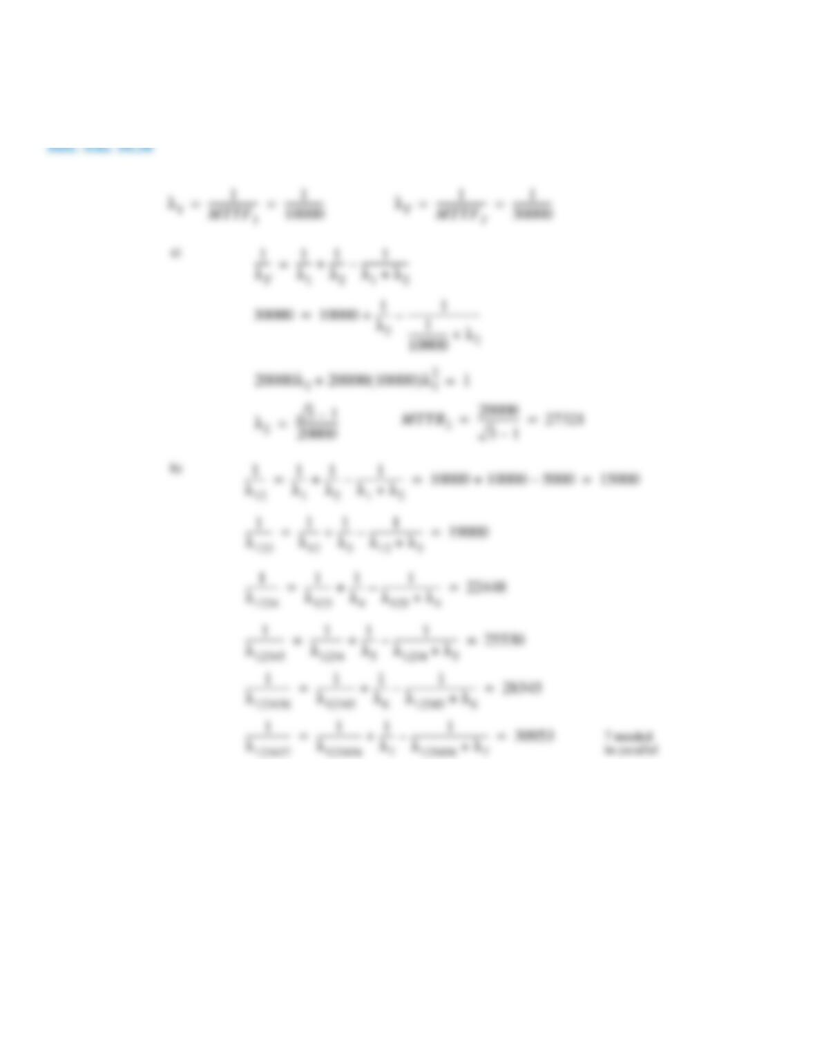
Problem 10.36
A system component has an MTTF of 10,000 hours but the customer requires 30,000. There are 2 design
options to be analyzed.
(a) If one component can be added in parallel what is its required MTTF?
(b) How many of the 10,000 MTTF components would be needed in parallel to meet the 30,000-hour MTTF?
Problem 10.37
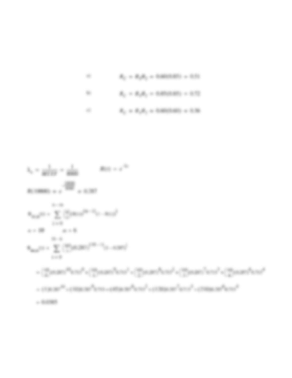
Two components are used in series. One component has been in use for 5000 hours and has a reliability of
0.60. The second component was replaced 1000 hours ago and has a reliability of 0.85.
(a) What is the combined reliability?
(b) What is the reliability if both components are 0.85 reliable?
(c) What is the reliability if both components are 0.60 reliable?
Inst. Ans. 10.37
Problem 10.38
A ship will still operate if 6 or more cylinders in a 10-cylinder engine are working. Each cylinder has an
MTTF of 8000 hours. What is the reliability of the engine at 10,000 hours?
Inst. Ans. 10.38
a)
R
C
R
1
R
2
0.60 0.85( ) 0.51= = =
b)
R
C
R
1
R
2
0.85 0.85( ) 0.72= = =
c)
R
C
R
1
R
2
0.60 0.60( ) 0.36= = =
λ
e
1
MTTF
–––––––––––––––– 1
8000
––––––––––––
= = R t( ) e
λt–
=
R10000( ) e
10000
8000
–––––––––––––––
–
0.287= =
Rm n; t( ) n
i
R t( )( ) n i–( ) 1 R t( )–( )i
i 0=
n m–
∑
=
Rm n; t( ) 10
i
0.287
( ) 10 i–( ) 1 0.287–( )i
i 0=
10 6–
∑
=
n
10
=m
6
=
10
0
0.287( )100.713010
1
0.287( )90.713110
2
0.287( )80.713210
3
0.287( )70.713310
4
0.287( )60.7134
+ + + +=
1( )
0.287
10
10( )
0.28790.713
45( )
0.28780.7132
120( )
0.28770.7133
210( )
0.28760.7134
+ + + +=
0.0385
=
Problem 10.39
A traffic light has three $30 traffic light modules. Each module has an MTTF of 30,000 hours. The labor to
replace the three modules is $50 during routine maintenance. However, if any one of the light modules fails, an
emergency crew must replace the three modules at a labor cost of $600. A standard policy is to replace the modules at
regular intervals before they have failed. What should the replacement interval be to minimize the costs?
Problem 10.40
A PLC-based control system has three parallel control modules. Each module has an MTTF of 20,000 hours.
The monitor has a MTTF of 50,000 hours. What is the combined reliability of the system?
Inst. Ans. 10.40
λ
T
1
30000
––––––––––––––– 1
30000
––––––––––––––– 1
30000
–––––––––––––––
+ + 1
10000
–––––––––––––––
= =
R t( ) e
t10000/–
=
3 30( ) 50+( )R t( ) 3 30( ) 600+( ) 1R t( )–( )=
830( )e
t10000/–
690( ) 1( )=
140( )e
t10000/–
t
–––––––––––––––––––––––––––––––––– 690( ) 1e
t10000/–
–( )
t
––––––––––––––––––––––––––––––––––––––––––––––––
=
t10000 690
830
–––––––––
ln– 1847= =
λ
e
1
MTTF
–––––––––––––––– 1
20000
–––––––––––––––
= =
1
λ
a
––––– 20000 20000 1
1
20000
––––––––––––––– 1
20000
–––––––––––––––
+
––––––––––––––––––––––––––––––––––––
–+ 30000= =
1
λ
p
––––– 20000 30000 1
1
20000
––––––––––––––– 1
30000
–––––––––––––––
+
––––––––––––––––––––––––––––––––––––
–+ 38000= =
λ
T
1
50000
––––––––––––––– 1
38000
–––––––––––––––
+ 0.46315789
-4
×10= =
MTTF 1
––––––––––––––––––––––––––––––––––––––––– 21591= =
Problem 10.41
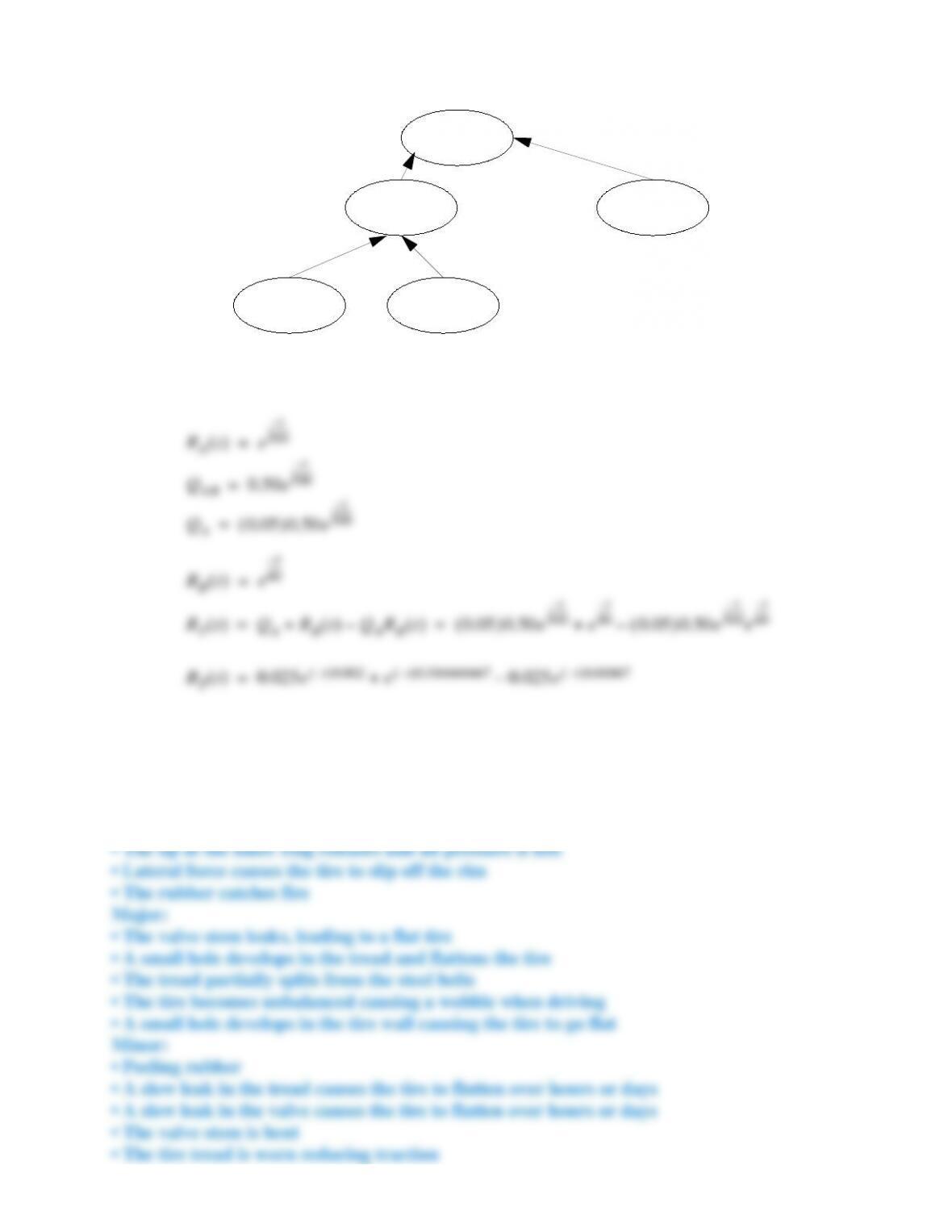
What is the probability that the system shown in the diagram will fail?
Inst. Ans. 10.41
Problem 10.42
Develop a list of five catastrophic, five major, and five minor faults for a car tire.
Inst. Ans. 10.42 Catastrophic:
• The tire wall splits open
• The tread separates from the walls
Failure
Event A
Q = 0.05 Device B
MTTF 60hr
Device A
MTTF 500hr
AND
Event B
Q = 0.50
R
A
t( ) e
t–
500
–––––––––
=
R
B
t( ) e
t–
60
––––––
=
Q
AB
0.50e
t–
500
–––––––––
=
Q
A
0.05( )0.50e
t–
500
–––––––––
=
R
T
t( ) Q
A
R
B
t( ) Q
A
R
B
t( )–+ 0.05( )0.50e
t–
500
–––––––––
e
t–
60
––––––
0.05( )0.50e
t–
500
–––––––––
e
t–
60
––––––
–+= =
R
T
t( ) 0.025e
t–( )0.002
e
t–( )0.016666667
0.025e
t–( )0.01867
–+=
Problem 10.43
Standards define reliability of devices. Find a published standard that lists minimum requirements for a
consumer product.
Problem 10.44
Case: The Challenger
The explosion of the Challenger space shuttle was the result of management failures in NASA and Morton Thiokol, and tech-
nical weaknesses.
(
See Challenger accident report PDF file on course website: www.engineeringdesignprojects.com/home/content/accident-
reports.
)
List five events where the chain of events could have been easily changed to prevent failure. The essential timeline is:
1972: Morton Thiokol was chosen to design the solid rocket boosters (SRBs) based on a modified Titan III rocket. One major
change was an O-ring seal along the rocket body that was made longer and a second O-ring added to provide a redundant seal.
1977–78: An engineering test showed that under pressure the joints rotated significantly causing the secondary O-ring to
become ineffective. Morton Thiokol management chose to accept the risk.
1980: The O-ring joint was listed as 1R on the critical item list (CIL), which indicates possible catastrophic failure. The “R”
indicates redundancy because of the second O-ring. There were 700 other items on the CIL.
1982: The space shuttle was declared operational. During the flights problems were identified and assigned a tracking number
to start problem solving. The O-ring problem was noticed but not assigned a number. Eventually the problem was noticed and
the CIL rating was changed from 1R to 1 to indicate that there was no backup. Morton Thiokol paperwork was not updated and
it still listed the seals as 1R. When pushed to recognize the change, Morton Thiokol disagreed with the criticality change and
went to a referee procedure.
1984: The O-ring erosion during launches became a significant issue. NASA asked for a review of the asbestos putty used to
reduce the heat effects on the O-rings. Morton Thiokol responded that the putty and O-rings were failing sooner because of the
higher-than-needed testing pressures, and this was confirmed with tests. It said it would investigate the effects of the tests.
January 1985: The space shuttle was launched at the coldest temperature in the history of the program. The cold stiffened the
O-rings and prevented them from deforming and sealing. After booster rocket recovery, the O-rings were examined and
showed the greatest degradation
of all flights.
January to April 1985: The flights continued and the issues with the O-rings persisted. The launch temperature and O-ring con-
dition were positively correlated. Morton Thiokol acknowledged the problem but stated that the second O-ring would ensure
safety.
April 1985: During a flight the primary O-ring did not seal and the secondary ring had to carry the pressure. The secondary O-
ring was showing degradation and would have eventually failed. The near failure of the backup resulted in a committee deci-
sion to set a minimum temperature for launches. The report was distributed within NASA and Morton Thiokol, but there were
questions about who received a copy and if they read it.
July 1985: To prevent a disaster, a Morton Thiokol engineer recommended that a team be set up to study the O-ring seal prob-
lem.
August 1985: Morton Thiokol and NASA managers briefed NASA headquarters on the O-ring problems, with a recommenda-
tion to continue flights but step up investigations. A Morton Thiokol task force was set up.
October 1985: The head of the Morton Thiokol task force complained to management about lack of cooperation and support.
December 1985: One Morton Thiokol engineer suggested stopping shipments of SRBs until the problem was fixed. Morton
Thiokol management wrote a memo to NASA suggesting that the problem tracking of the O-rings be discontinued. This led to
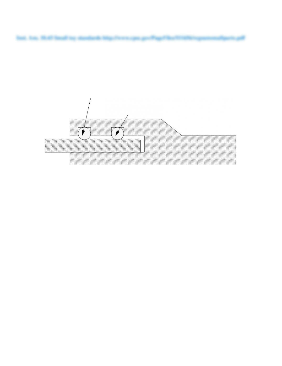
Secondary O-ring
Primary O-ring

an erroneous listing of the problem as closed, meaning that it would not be considered as critical during launch.
January 1986: The space shuttle Challenger was prepared to launch on January 22; originally it was scheduled for July 1985
and postponed three times and scrubbed once. It was rescheduled again to the 23rd, 25th, 27th, and then 28th. This was a result
of weather, equipment, scheduling, and other problems.
January 27, 1986: The shuttle began preparation for launch the next day, despite predicted temperatures below freezing (26ºF
or –3ºC) at launch time. Thiokol engineers expressed concerns over low temperatures and suggested NASA managers be noti-
fied (this was not done). A minimum launch temperature of 53ºF had been suggested to NASA. There was no technical opin-
ion supporting the launch at this point. The NASA representative discussing the launch objected to Thiokol’s engineer’s
opinions and accused them of changing their opinions. Upper management became involved with the process and “convinced”
the technical staff to withdraw objections to the launch. Management at Thiokol gave the go-ahead to launch, under pressure

Problem 10.45
Mini-case: Space units
In December 1998 the U.S. Mars Climate Orbiter was launched and began the trip to Mars. By September 1999 the satellite
reached Mars and was preparing to enter a permanent orbit. This process involved adjusting the path to be tangential to the
desired orbit circle. The rocket was slowed so that when it was near the tangential point, the satellite velocity matched the
orbital velocity. If the satellite was too slow, or too close to the planet, it would crash. If the satellite was too fast, or too far
from the planet, it would miss. As the Orbiter approached the planet four 22 N side thrusters were available to adjust the
approach angle and a 640 N braking engine was available to slow the Orbiter from interplanetary speeds to orbital speeds. The
ground crew, on earth, monitored the trajectory of the satellite and used it to calculate the burn times for each of the engines to
achieve orbit. There was a radio delay of several minutes, so the team uploaded the calculated values and then waited. Nor-
mally the satellite would have done the calculated burns, achieved orbit, and then sent a status update. For this satellite the sta-
tus update never came. Needless to say, there was some concern over the $327 million failure. The executive summary from a
report on the failure follows ( NASA, 1999 ). (
See MCO accident report PDF fi le on course website: www.engineeringdesignprojects.com/
home/content/accident-reports.
)
This Phase I report addresses paragraph 4.A. of the letter establishing the Mars Climate Orbiter (MCO) Mishap Investigation
Board (MIB) (Appendix). Specifically, paragraph 4.A. of the letter requests that the MIB focus on any aspects of the MCO
mishap which must be addressed in order to contribute to the Mars Polar Lander’s safe landing on Mars. The Mars Polar
Lander (MPL) entry-descent-landing sequence is scheduled for December 3, 1999.
This report provides a top-level description of the MCO and MPL projects (section 1), it defines the MCO mishap (section 2)
and the method of investigation (section 3) and then provides the Board’s determination of the MCO mishap root cause (sec-
tion 4), the MCO contributing causes (section 5) and MCO observations (section 6). Based on the MCO root cause, contribut-
ing causes and observations, the Board has formulated a series of recommendations to improve the MPL operations. These are
included in the respective sections. Also, as a result of the Board’s review of the MPL, specific observations and associated
recommendations pertaining to MPL are described in section 7. The plan for the Phase II report is described in section 8. The
Phase II report will focus on the processes used by the MCO mission, develop lessons learned, and make recommendations for
future missions.
The MCO Mission objective was to orbit Mars as the first interplanetary weather satellite and provide a communications relay
for the MPL which is due to reach Mars in December 1999. The MCO was launched on December 11, 1998, and was lost
sometime following the spacecraft’s entry into Mars occultation during the Mars Orbit Insertion (MOI) maneuver. The space-
craft’s carrier signal was last seen at approximately 09:04:52 UTC on Thursday, September 23, 1999. The MCO MIB has
determined that the root cause for the loss of the MCO spacecraft was the failure to use metric units in the coding of a ground
software file, “Small Forces,” used in trajectory models. Specifically, thruster performance data in English units instead of
metric units was used in the software application code titled SM_FORCES (small forces). A file called Angular Momentum
Desaturation (AMD) contained the output data from the SM_FORCES software. The data in the AMD file was required to be
in metric units per existing software interface documentation, and the trajectory modelers assumed the data was provided in
metric units per the requirements.
During the 9-month journey from Earth to Mars, propulsion maneuvers were periodically performed to remove angular
momentum buildup in the on-board reaction wheels (flywheels). These Angular Momentum Desaturation (AMD) events
occurred 10–14 times more often than was expected by the operations navigation team. This was because the MCO solar array
was asymmetrical relative to the spacecraft body as compared to Mars Global Surveyor (MGS) which had symmetrical solar
(2) Navigation Team unfamiliar with spacecraft
(4) System engineering process did not adequately address transition from development to operations
(6) Inadequate operations Navigation Team staffing

(8) Verification and validation process did not adequately address ground software
MPL Recommendations:
●
Verify the consistent use of units throughout the MPL spacecraft design and operations
●
Conduct software audit for specification compliance on all data transferred between JPL and Lockheed Martin Astronautics
●
Verify Small Forces models used for MPL
●
Compare prime MPL navigation projections with projections by alternate navigation methods
●
Train Navigation Team in spacecraft design and operations
●
Prepare for possibility of executing trajectory correction maneuver number 5
●
Establish MPL systems organization to concentrate on trajectory correction maneuver number 5 and entry, descent and land-
ing operations
●
Take steps to improve communications
●
Augment Operations Team staff with experienced people to support entry, descent and landing
●
Train entire MPL Team and encourage use of Incident, Surprise, Anomaly process
●
Develop and execute systems verification matrix for all requirements
●
Conduct independent reviews on all mission critical events
●
Construct a fault tree analysis for remainder of MPL mission
●
Assign overall Mission Manager
●
Perform thermal analysis of thrusters feedline heaters and consider use of preconditioning pulses
●
Reexamine propulsion subsystem operations during entry, descent, and landing
Given the summary, select two MPL recommendations that should be a high priority. Explain your choice.