CHAPTER 10
HEAT EXCHANGER MODEL
OBJECTIVES
• Apply the principles of heat transfer to problems found in this chapter.
• Identify and describe the basic components of a heat exchanger system.
• Draw a simple block-flow diagram of a heat exchanger system.
• List and draw the two control loops used on the heat exchanger system.
• Identify the simple instrument used by a technician to operate the heat transfer
system.
• Explain the primary purpose of each control loop and explain how the two control
loops work and compliment each other.
• Operate the heat exchanger system.
• Identify the common problems associated with heat exchanger systems.
• Solve various troubleshooting scenarios associated with heat exchanger systems.
• Compare and contrast the set point, process variable, and valve operating
percentage.
REVIEW QUESTIONS
1. Describe the purpose of FIC 202, and how it works.
Flow Control Loop FIC 202
The flow control loop is designed to work with the pump and the
backpressure available to the control valve. Figure 10-4 illustrates the basic
components of FIC-202. The basic components of FIC-202 are:
• orifice plate
• flow transmitter
• flow indicator controller
unique relationship as the control valve begins to throttle flow. This throttling
effect does not hurt the pump or valve as the principle of internal slip protects the
system. This is not the case when a positive displacement pump is used. PD
2. Describe the purpose of TIC 100, and how it works.
Temperature Control Loop TIC-100
The temperature control loop utilizes a hot oil system to heat up the feed to
C-202. The set point for the system is 180ºF @ 225 GPM @ 135 psig. Figure
10-5 illustrates Temperature Control Loop 100. The basic components of TIC-100
include:
• Temperature recorder 100
3. What is the controlled flow rate of P-202?
4. What is the flow rate of P-100 to Ex-203?
5. What is the initial feed temperature to C-202?
6. What is the temperature differential across the shell side of Ex-202?
7. What is the temperature differential across the tube side of Ex-202?
8. What is the temperature differential across the shell side of Ex-203?
65.5ºF
9. What is the temperature differential across the tube side of Ex-203?
10. Describe the purpose and operation of AT-1.
11. Describe the primary difference between Ex-202 & Ex-203?
The primary difference between Ex-202 and Ex-203 is the application of a hot oil
12. Draw a process flow drawing for the heat exchanger system. List all instruments
and control systems.
13. Define the term, “tube growth.”
14. Explain the various methods of heat transfer used in the heat exchanger
system.
15. Define the term, “fouling.”
Fouling– buildup on the internal surfaces of devices such as cooling towers and
16. Describe the correct procedure for starting up the heat exchanger system.
1. Verify pump recirculation to Tk-202. This includes looking at pump suction
and discharge pressures and level in Tk-202.
17. What temperature differentials are associated with fixed head and floating head
heat exchangers.
Ex-202 and Ex-203 are characterized as shell and tube, multi-pass, floating head
heat exchangers. Floating head heat exchangers are designed for high
temperature differentials above 200ºF. During operation, one tube sheet is fixed
and the other “floats” inside the shell. The floating end is not attached to the
18. Identify the instruments associated with Ex-202.
19. Identify the instruments associated with Ex-203.
20. Compare and contrast the various pump systems and operating circuits on
the heat exchanger system.
Pump 202 is a horizontally mounted centrifugal pump designed to operate at 225
NAME:____________________________ TEST A
DATE:____________________________
CHAPTER TEN
TEST HEAT EXCHANGER MODEL
1. Fouling resistance is determined by all of the following except:
a. type of fluid being handled
b. amount of suspended solids
c. tube and shell pressure rating
d. velocity of fluid stream
2. A device mounted on the inlet side of a shell and tube heat exchanger that is
used to channel flow in a multi-pass heat exchanger.
a. head
b. longitudinal baffle
c. sectional head
d. channel head
3. Laminar flow transfers heat more effectively than turbulent flow inside a heat
exchanger.
a. true
b. false
4. Internal buildup on the surface area of a heat exchanger that results in a
restriction is referred to as:
a. plugging
b. fouling
c. scale
d. purging
5. A type of heat exchanger that channels the tube-side flow across the tube bundle
more than once.
a. multi-pass
b. u-tube
c. a & b
d. floating head
e. a & b & d
6. What is the name of the metal plates located inside a shell and tube heat
exchanger that are designed to increase turbulent flow and reduce hotspots.
a. vertical baffles
b. impingement baffle
c. longitudinal baffles
d. all the above
7. All of the following are examples of heat transfer found in a heat exchanger
except:
a. convection
b. conduction
c. sensible
d. radiant
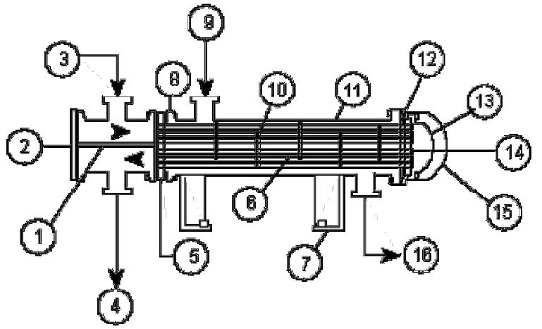
8. List the parts of a floating head heat exchanger.
Figure 10-1 Shell and Tube Heat Exchanger Components
8-1__________ 8-2__________ 8-3__________ 8-4__________
8-5__________ 8-6__________ 8-7__________ 8-8__________
8-9__________ 8-10__________ 8-11__________ 8-12__________
8-13__________ 8-14__________ 8-15__________ 8-16__________
9. A term used to describe flow in a heat exchanger where tube-side flow and shell-
side flow go in opposite directions.
a. cross flow
b. horizontal flow
c. parallel flow
d. counter flow
10. On a simple shell and tube heat exchanger a process technician would close
which of the following valves first.
a. tube inlet valve #1- process fluid 125 F
b. tube outlet valve #2- process fluid 325 F
c. shell inlet valve #3- steam
d. shell outlet valve #4- steam
11. On a simple shell and tube heat exchanger a process technician would turn the
device into a bomb if he closed which of the following valves first.
a. tube inlet valve #1- process fluid 125 F
b. tube outlet valve #2- process fluid 325 F
c. shell inlet valve #3- steam
d. shell outlet valve #4- steam
12. The difference between inlet and outlet pressures is commonly referred to as:
a. differential pressure
b. approach to the exchanger
c. ∆ P (delta P)
d. a & c
13. A term used to describe flow in a heat exchanger where tube-side flow and shell-
side flow go in the same directions.
a. cross flow
b. horizontal flow
c. parallel flow
d. counter flow
14. A term used to describe flow in a heat exchanger where shell-side flow vertically
crosses the horizontal tube flow.
a. cross flow
b. horizontal flow
c. parallel flow
d. counter flow
15 Sudden temperature changes that results in the rapid expansion or contraction of
metal.
a. thermal shock
b. fluid dynamics
c. warping
d. hydraulics
16. A baffle that is designed to deflect high velocity fluids inside a heat exchanger.
a. longitudinal baffle
b. horizontal baffles
c. vertical baffles
d. impingement baffles
17. A type of heat exchanger that uses a tubular bundle to heat and flash a liquid in
an over-sized shell with a vapor disengaging cavity.
a. kettle
b. thermosiphon
c. pot belly reboiler
d. a & c
18. The tub head on a floating head heat exchanger is firmly attached to the tube
sheet.
a. true
b. false
19. Inside a tube with streamline fluid flow temperatures are relatively constant.
a. true
b. false
20. The heat exchanger that is designed to take the highest flow rates and largest
temperature differences is:
a. u-tube
b. plate and frame
c. double-pipe
d. fixed heads, multipass
21. A process technician can reduce fouling in a heat exchanger by: Circle all that
apply!
a. increasing fluid velocity
b. decreasing fluid velocity
c. lowering the temperature
d. increasing the temperature
e. removing inhibitors
f. adding inhibitors
22. A layer of fluid that tends to adhere to the walls of a heat exchanger is referred
to as:
a. laminar adhesion
b. static film
c. crystallization
d. slack
23. Heat exchanger effectiveness is linked to all of the following except:
a. cross sectional area
b. ∆p
c. flow rate
d. differential temperature
e. electromagnetic wave intensity
24. Turbulent flow allows molecules of fluid to mix and absorb heat energy better
than laminar but it enhances the stationary film along the shell and tube walls.
a. true
b. false
25. Fins are added to tubes because:
a. thin material transfers heat better
b. fins create turbulence
c. fins enhance laminar flow
d. a & b
26. A shell and tube heat exchanger can be used to heat and cool a substance.
a. true
b. false
27. Tube growth is most closely defined as:
a. a process of thermal expansion where the tubes expand evenly in all
directions.
b. a process of thermal expansion where the tubes expand length-wise.
c. a process of thermal expansion, corrosion, and time.
d. a process associated with expansion and contraction at the tube sheet.
28. Floating head heat exchangers are designed for high temperature differentials –
_______________ .
a. slightly above 545ºF
b. slightly below 100ºF
c. above 200ºF
d. above 600ºF
29. AT-1 is primarily designed to detect:
a. Pentane
b. Propane
c. Butane
d. Heptane
30. FIC-202 is designed to operate at:
a. 175ºF
b. 225ºF
c. 200ºF
d. 325ºF
31. The hot oil system has a flow rate of:
a. 225 GPM
b. 325 GPM
c. 430 GPM
d. 625 GPM
32. TIC-100 has a set point of:
a. 160.5ºF
b. 180ºF
c. 195ºF
d. 212ºF
33. The primary feed pump for the process is:
a. P-202
b. P-100
c. P-208
d. P-209
34. Original feed temperature is:
a. 180ºf
b. 212ºF
c. 60ºF
d. 80ºF
35. Ex–202’s shell outlet temperature is:
a. 115ºF
b. 180ºF
c. 100ºF
d. 80ºF
36. Ex–203’s temperature delta is:
a. 25ºF
b. 45ºF
c. 65ºF
d. 95ºF
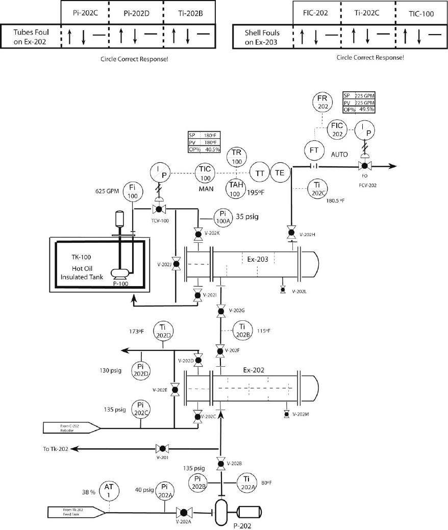
37. Heat Exchanger TS#1
1.
2.
3.
4.
5.
6.
38. Heat Exchanger TS#2
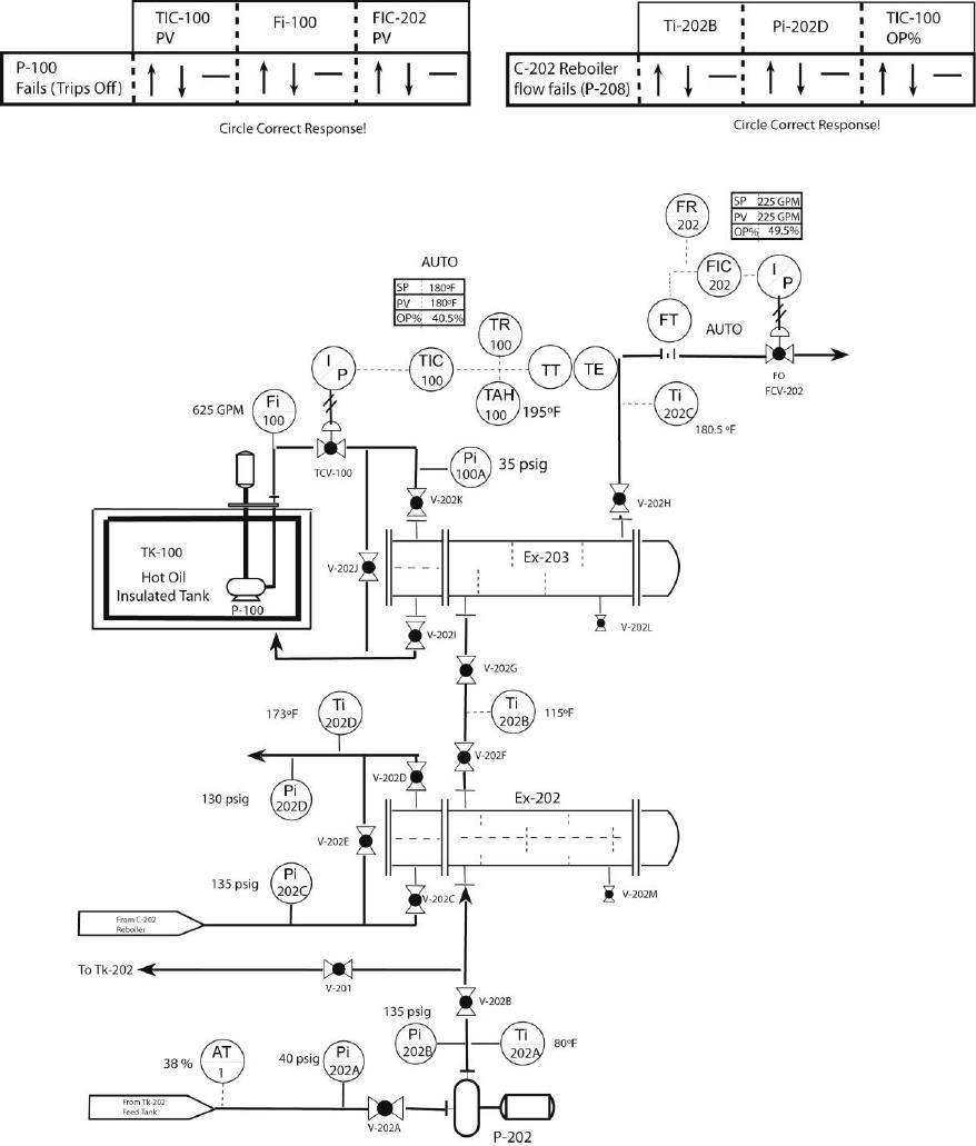
1.
2.
3.
4.
5.
6.
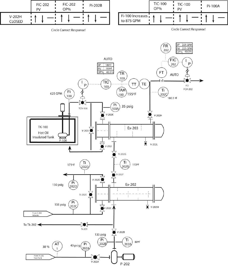
39. Heat Exchanger TS#3
1.
2.
3.
4.
5.
6.
Answer Key CHAPTER 10 TEST A
HEAT EXCHANGER MODEL